A receptacle that sits proud of the wall is not always a cover problem. Behind it, a deep device, a connector and a rear cable entry may be competing for the same narrow space. Tightening the screws harder can conceal the problem while stressing conductors or preventing the device from seating correctly. A shallow wall also rules out the simple advice to buy a deeper box. This guide explains how to diagnose the actual depth constraint, compare product drawings and choose a permitted arrangement without confusing physical fit with acceptable wiring capacity.
A shallow electrical box is a lower-depth option within a particular product family, not one universal standardized depth. For example, RACO lists a three-gang 952 welded box at 1-5/8 in deep and a three-gang 942 at 2-1/2 in deep. Whether either works depends on the installation method, available wall space, device projection and required fill. First measure the finished-wall cavity and the complete device arrangement. Then compare the exact box, cover and entry fittings; do not compress the conductors or use an unapproved modification to make a shallow enclosure appear adequate.
Which part of the installation is consuming the depth?
Measure from the finished surface to the obstruction behind the proposed box. The wall may contain masonry, a stud flange, another service or a fitting that prevents the full nominal depth from being used. A bare framing measurement can be misleading once tile, board and a mounting ring are installed.
Next separate the box depth from the device’s installed projection. Terminals and connectors need room as well as the device body. A rear entry may place the conductor bend directly behind the deepest part of a smart switch or GFCI receptacle. Moving to a different permitted entry arrangement can matter, but only when the actual box and wiring instructions allow it.
| Observed problem | Dimension to check | Decision boundary |
|---|---|---|
| Box hits the back wall | External depth and fitting projection | Choose a permitted enclosure that fits |
| Device will not seat | Installed device depth and connector position | Do not force it with the screws |
| Wiring is crowded | Marked volume and actual fill | Physical closure does not prove compliance |
| Cover sits incorrectly | Finished-wall position and matching ring | Check the approved assembly |
How do shallow and deeper models compare?
Der RACO 952 product is described as a welded three-gang box with a 1-5/8 in depth. The RACO 942 product is a welded three-gang box with a 2-1/2 in depth. The difference is 7/8 in for these two published examples. These records, checked October 19, 2026, establish a real depth comparison without pretending that all shallow boxes have the same dimensions.
Der depth of junction box assemblies should also include the selected cover and external fittings where they affect the installation. A box’s published volume should be read directly from its own record or marking; it should not be inferred by multiplying external dimensions, since construction and internal features affect usable space.
| Option | Potential reason to consider it | Required verification |
|---|---|---|
| Shallower listed box | Limited cavity behind the wall | Device clearance and calculated fill |
| Deeper compatible box | More room behind a deep device | Wall clearance, mounting and entry layout |
| Permitted surface arrangement | Insufficient concealed cavity | Approved box, fittings and exposed installation |
| Different suitable device | Installed device projection is the constraint | Electrical function and mounting compatibility |
| Redesigned wiring arrangement | Connectors or entries block access | Permitted wiring method and accessible connections |
How do you build a useful depth budget without confusing it with box fill?
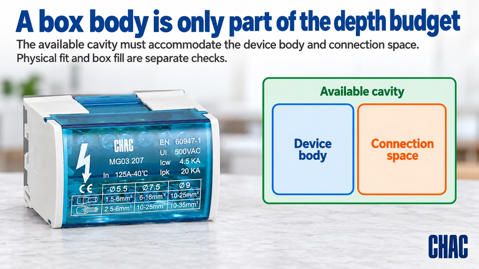
Draw the device and entry fittings from a shared mounting plane, using the actual internal envelope rather than the box’s nominal outside depth. For a simplified hypothetical example, assume 2.0 in of usable depth behind the mounting plane and a device projecting 1.4 in into it. That leaves 0.6 in in the same rearward direction before considering a connector, conductor route or other obstruction. None of those assumed dimensions describes a particular product.
The remaining 0.6 in is not a permitted conductor allowance or a box-fill calculation. Parts can occupy different regions, and their envelopes may overlap differently from a simple stack. Check the proposed routes on the assembly drawing and, where necessary, a de-energized sample. Record the first actual interference. This identifies whether the limiting item is the box shell, the device, an entry fitting or the wiring arrangement, rather than treating every seating problem as insufficient total volume.
Can a shallow box pass fill checks and still be difficult to use?
Yes. Required volume is one acceptance condition; conductor routing and assembly access are another. A device can occupy the central space while connectors sit at the sides, but that arrangement must remain practical without damaging insulation or exceeding product instructions. It should not depend on a precise fold that cannot be reproduced during maintenance.
Apply the adopted box-fill rules to the actual circuit. Different items can have different counting treatment, and grounding-conductor provisions depend on the applicable rules. A generic statement that a box holds a certain number of wires is incomplete when devices, clamps or other components are added. Have the calculation checked for the intended installation rather than treating an online capacity example as a permit-ready design.
When should the installation be redesigned?
If no suitable box can meet both the cavity limit and the wiring requirement, the constraint is real. A permitted surface box, a relocated device or another approved arrangement may be necessary. An extension ring is not automatically suitable for every enclosure or wall system; confirm the manufacturer’s compatibility and how the finished assembly is approved.
Do not remove required box parts, cut away a mounting feature or leave connections behind an inaccessible cover to gain space. Material choice must also remain suitable for the wiring system and environment. Metal requires the applicable bonding arrangement, while nonmetallic construction does not remove the need for correct entries, fastening and any wall-assembly conditions.
What must an extension proposal show before it solves the depth problem?
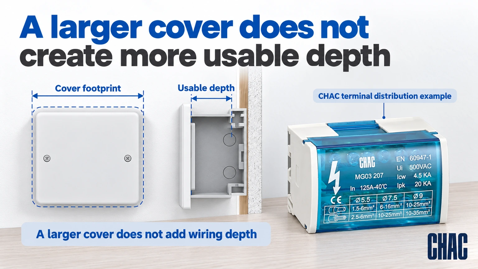
Request the exact box, extension or raised cover, device mounting arrangement and compatible fasteners as one proposal. Ask which documented volume may be included in the applicable fill evaluation and where the finished device plane will sit. Do not assume that a raised decorative face creates approved wiring space, or that every extension can be attached with longer device screws.
Also check any required bonding, cover engagement, wall-assembly conditions and entry access after the change. A proposal may solve the rear clearance while creating an unacceptable front projection or preventing the cover from seating. Mark both positions on the drawing and obtain the relevant manufacturer instructions. If the proposed combination has no supporting compatibility information, retain the unresolved status and evaluate another permitted arrangement rather than describing the extension as a completed repair.
What should be confirmed before ordering a replacement box?
Record the available cavity, finished-wall position, device model, conductor and connector arrangement, mounting method and required approval. Request the replacement’s drawing and installation instructions, then compare the complete assembly. This makes electrical box depth a defined requirement rather than a guess based on the old cover.
CHACs distribution junction box connection assembly is a terminal and bus connection product, not a shallow outlet box. Its documented dimensions are relevant to cabinet layouts that use that function. For related projects, consult the distribution and control product range while keeping the wall enclosure and device specification separate.
What are the common questions about shallow electrical boxes?
What is the shallowest electrical box you can get?
The answer depends on the product family and intended installation. Choose from approved models that meet the wiring and device requirements, rather than selecting the smallest advertised depth alone.
What is the minimum depth of an electrical box?
There is no single minimum suitable for every device and circuit. Check the applicable installation rules, device instructions, capacity and enclosure approval.
What are shallow electrical boxes used for?
They can serve installations where the available cavity is limited, provided the chosen box remains suitable for the devices, wiring method, fill and mounting conditions.
What are the dimensions of a shallow electrical box?
They are model-specific. The cited RACO 952 example is 1-5/8 inches deep, but that does not define every shallow box or its required opening.
What are the standard sizes for shallow electrical box?
Compare the exact height, width, depth and capacity within the chosen manufacturer range. The shallow label alone does not identify these values.
How deep should shallow electrical box be for the wiring inside?
Deep enough for the permitted device and conductor arrangement while meeting fill requirements, and shallow enough to fit the real cavity. If both cannot be met, redesign the installation rather than forcing the wiring.
Verweise
- Hubbell RACO 952: three-gang 1-5/8-inch-deep box; accessed October 19, 2026
- Hubbell RACO 942: three-gang 2-1/2-inch-deep box; accessed October 19, 2026
- Hubbell RACO enclosure families and accessories; accessed October 19, 2026
Conclusion
A shallow-box problem is solved by identifying the space constraint, not by hiding it behind a larger faceplate. Check the finished cavity, the installed device and the conductor arrangement before comparing replacement enclosures. Then verify capacity, mounting, entries and any approved cover or extension as one assembly. If the required wiring cannot fit appropriately, change the installation arrangement rather than crushing conductors or modifying the box without approval. Model-specific depth examples help compare options, but they do not establish a universal minimum or guarantee device compatibility. CHAC provides documented connection and distribution components for relevant cabinet applications. Use the exact model information for those functions and a separately verified wall-box specification where the project needs an outlet enclosure.
For the relevant model drawings and project documentation, contact CHAC with the circuit requirements.