Can a breaker with the right ampere rating protect both a PV string and a battery connection? Not on that information alone. A PV string’s maximum open-circuit voltage depends on temperature, while a battery or connected converter can change the available fault current and its direction. A device described as non-polarized still needs documented interruption ratings for the proposed circuit. Confusing those checks can leave an apparently suitable purchase outside its published conditions and force a redesign. The selection path below separates voltage, current-carrying duty, fault interruption and isolation so that each decision can be checked against project data and exact model instructions.
The short answer is to select a DC circuit breaker from the circuit’s maximum voltage, continuous design current, conductor limit, prospective fault current, polarity, pole configuration and isolation plan, not from panel wattage alone. IEC 60947-2:2024 covers circuit-breakers within its scope up to 1,500 V DC, but that scope does not make every breaker suitable for every PV circuit. Calculate the project inputs, identify each source and fault-current direction, then verify the exact model’s DC voltage and breaking capacity in the permitted connection arrangement. Neither an AC rating nor a claim about current direction substitutes for that evidence.
Welche Spannungs-, Strom- und Fehlerdaten sollten Sie zuerst erfassen?
Der Amperewert eines Schutzschalters ist nur ein Teil der Entscheidung. Die maximale Spannung muss die höchste Spannung abdecken, die bei der vorgesehenen Installation über dem Gerät auftreten kann. Für einen PV-String bedeutet dies, die Leerlaufspannung bei der niedrigsten Projektdesign-Temperatur unter Verwendung der Spannungs-Temperatur-Daten des Modulherstellers und der geltenden Designmethode zu überprüfen. Die unter Standardtestbedingungen aufgedruckte Betriebsspannung ist nicht das Maximum bei kaltem Wetter.
Keep two different values on the calculation sheet: the string’s temperature-corrected maximum open-circuit voltage (Voc), derived from the module data and series count, and the breaker’s published DC operational voltage for its permitted pole connection. They come from different documents. Schneider Electric’s Fundamental characteristics of a circuit-breaker distinguishes rated operational voltage, rated current and breaking capacity. Its AC fault-current discussion uses rms current and power factor; those AC examples must not be treated as a DC interrupting rating or a CHAC test result.
Für den Strom ist ein ähnlich disziplinierter Weg erforderlich. Beginnen Sie bei den Quelldaten und der Schaltungsarchitektur, wenden Sie die für das Zielprojekt erforderliche Designmethode an und überprüfen Sie, ob die ausgewählte Schutzeinstellung oder Bemessung den zulässigen Strom des geschützten Leiters unter den tatsächlichen Installations- und Umgebungsbedingungen nicht überschreitet. Durch eine Nennspannung geteilte Schaltschrank-Wattzahlen können in manchen Zusammenhängen eine nützliche Lastabschätzung sein, sie bestimmen jedoch weder die maximale PV-Spannung, den Quellen-Kurzschlussstrom, die Strombelastbarkeit der Leiter, die Rückstrombelastung noch das erforderliche Ausschaltvermögen des Schutzschalters.
| Berechnungs- oder Verifizierungseingabe | Aufzuzeichnende Beweise | Entscheidung, die sie unterstützt | Freigabegrenze |
|---|---|---|---|
| Maximale Sch circuito-Spannung / Maximale Schaltkreisspannung -> Maximale Schaltkreisspannung | Anzahl der Module in Reihe, Leerlaufspannung und Temperaturkoeffizient des Moduls, niedrigste Bemessungstemperatur oder maximale Ausgangsleistung der Quelle | Erforderliche Gleichspannung und zulässige Polanordnung | Wenden Sie die anwendbare Projektmethode an; ersetzen Sie nicht die Nennbetriebsspannung |
| Dauerbemessungsstrom | Kurzschlussstrom des Moduls oder Quellen-/Lastdaten, parallele Pfade, erwartete Last und Bestimmungsort-Entwurfsregeln | Schaltnennstrom oder -einstellung | Es gibt keinen universellen Multiplikator, der für jede Rechtsordnung, jede Quelle oder jedes Produkt passt. |
| Zulässige Stromstärke des Leiters | Leiterquerschnitt, Isolierung, Verlegeart, Bündelung, Umgebungstemperatur und anwendbare Korrekturfaktoren | Obergrenze für die Auswahl der Überstromschutzeinrichtung | Bestätigen Sie anhand der geltenden Verdrahtungsvorschriften und Leiterdaten |
| Voraussichtlicher Kurzschlussstrom | Schutzstudie am Einspeisepunkt, einschließlich beitragender Quellen und Richtung | Erforderliches DC-Schaltvermögen und Koordinationsprüfung | Fehlerenergie von Batterien oder Bussen nicht aus dem PV-String-Verhalten ableiten |
| Polarität und Polanordnung | Systemerdung, Anordnung der Leiter, einpoliger Schaltplan und exakter Schalteranschlussplan | Welche Leiter öffnen und ob Reihenpole zulässig oder erforderlich sind | Die Anweisungen des Modells haben Vorrang; das Schaltbild eines anderen Schutzschalters ist kein Beweis. |
| Installationsbedingungen | Gehäuse, Umgebungstemperaturbereich, Höhenlage, Anschluss-/Leitergrenzwerte und Montageausrichtung | Derating, Passgenauigkeit und Umwelteignung | Verwenden Sie die veröffentlichten Grenzwerte für die genaue Katalognummer |
Ein anschaulicher Berechnungsnachweis sollte daher Eingaben und Methode zeigen, bevor eine ausgewählte Katalognummer angezeigt wird. Wenn eine Modulspezifikation, eine Mindesttemperatur, ein Leiterzustand oder eine Fehlerstromanalyse fehlt, ist das vertretbare Ergebnis “Auswahl ausstehend” und keine geschätzte Bemessung. Diese Pause verhindert Fehlauslösungen, überhitzte Leiter, ein unterdimensioniertes Schaltgerät und kostspielige Nacharbeiten vor Ort.
Can an AC-Rated Breaker Also Be Suitable for DC?
Ein Wechselstromlichtbogen profitiert von einem natürlichen Nulldurchgang des Stroms; eine Gleichstromunterbrechung weist diese Wellenformbedingung nicht auf. Ein Leistungsschalter muss daher eine veröffentlichte Gleichstrombemessung für die Schaltungsspannung, den Strom, das Ausschaltvermögen und die Anschlussanordnung aufweisen. Der dazugehörige Leitfaden zu DC-Leitungsschutzschalter und AC-Schaltkreiskompatibilität Erklärt, warum ein AC-Typenschild allein keine sichere Zulassungsgrundlage ist.
Dual-rated products do exist. In AC MCBs vs DC MCBs: The Difference is More Than a Letter!, c3controls identifies its own Series 1100 products as suitable for AC and DC with different operating voltages. That is a manufacturer-specific example, not permission to reuse an AC rating on DC or evidence that a CHAC model has the same ratings.
| Auswahldimension | Was muss abgeglichen werden | Kosten einer schwachen Annahme |
|---|---|---|
| Spannung | Zulässige DC-Spannung für die zulässige Verdrahtung und Polanordnung | Die Auswahl liegt möglicherweise außerhalb der demonstrierten Unterbrechungsbedingungen des Geräts |
| Strom- und Leiterschutz | Bemessungsstrom, Gerätenennstrom oder -einstellung, Leitergrenzwert und umgebungsbedingte Reduzierung | Fehlauslösung oder unzureichender Leiterschutz |
| Ausschaltvermögen | Voraussichtlicher Kurzschlussstrom am Installationsort | Abgelehntes Design, Koordinationsfehler oder Geräteaustausch |
| Polarität und Pole | Genaue Klemmenbezeichnungen des Herstellers und zugelassener Reihungsanschluss | Fehlverdrahtung, nicht bestandene Inspektion oder Verlust der erklärten Bemessungsgrundlage |
| Funktionsabdeckung | Überstrom-, Isolierungs-, Überspannungs-, Erdschluss- und Störlichtbogenfunktionen separat zugeordnet | Eine erforderliche Schutzfunktion kann trotz richtig dimensioniertem Leistungsschalter fehlen. |
| Dokumentation | Rückverfolgbarer Einzeiler, Datenblatt, Anweisungen und finaler Anschlussplan | Beschaffungssubstitutionen und Inbetriebnahmefehler werden schwieriger zu erkennen |
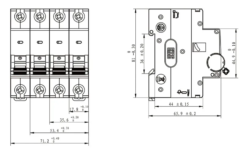
How Do PV, Battery, and DC Distribution Circuits Differ?
Der Ausdruck Solar-DC-Schutzschalter definiert keine universelle Pflicht. Ein PV-Strang ist eine strombegrenzte Quelle, deren Rückstrombelastung von anderen parallelen Strängen oder angeschlossenen Geräten ausgehen kann. Eine Batterie kann einen hohen Fehlerstrom in eine andere Richtung und mit einem anderen Zeitprofil liefern. Ein DC-Verteilerbus kann mehrere beitragende Quellen und eine Koordinierungsanforderung mit upstream- und downstream-Geräten aufweisen. Die Quelle und der Strompfad müssen gezeichnet werden, bevor das Schutzgerät bewertet werden kann.
| Systemgrenze | Strom- und Fehlerfrage | Breaker-Test | Projektumfang-Grenze |
|---|---|---|---|
| PV-String oder Unterarray | Wie hoch sind der Strangbetriebsstrom, der Quellen-Kurzschlussstrom und mögliche Rückstrombeiträge von Parallelen? | Kaltmaximale Spannung, Leiterschutz, Polarität, Polanordnung und PV-Quellen-Schaltbedingungen | PV-Modulfeld-Auslegungsregeln anwenden; Modulfeld-Einlinienschaltbild und Anschlussrichtung erfassen |
| Batteriebranche | Welchen Fehlerstrom können die Batterie und die angeschlossene Sammelschiene liefern, und von welcher Seite aus? | Bemessungs-Ausschaltvermögen, Richtungs-/Polungsvorgaben, Leiterséhutz und Koordination in der Nähe der Quelle | IEC 62548-1 schließt Energiespeicher aus; holen Sie sich die Planung von Batteriesystemen und die geltenden Regeln separat ein. |
| Gleichstromverteilungsausgang | Welche vorgelagerten Quellen tragen zu einem nachgeschalteten Fehler bei, und ist eine Rückeinspeisung möglich? | Schaltvermögen, Selektivität, bidirektionale Eignung wo erforderlich und Lastcharakteristik | Eine PV-Anlagen-Regelung steuert nicht automatisch das Last-/Verteilernetz |
| PV-Speicher-Schnittstelle | Können entweder die PV-Seite, die Speicherseite oder der Umrichter den Fehlerort speisen? | Bewerten Sie jedes Gerät an seinen tatsächlichen Klemmen und im Betriebszustand | Teilen Sie die Studie an definierten Schnittstellen auf; führen Sie ungleiche Quellannahmen nicht zusammen. |
Diese Randgruppenmatrix ist ein Screening-Werkzeug, keine Kurzschlussstudie. Sie macht ein Beschaffungsrisiko sichtbar: Eine Teilenummer, die an einem PV-String akzeptabel ist, ist an einer Batterie-Zuleitung nicht automatisch akzeptabel, nur weil Spannung und Nennstrom ähnlich erscheinen.
How Do Poles, Polarity, and Isolation Affect DC Breaker Selection?
Für PV circuit protection, Die Polanzahl wird nicht aus Gewohnheit gewählt. Sie richtet sich nach der Systemerdung, den zu trennenden Leitern, der Spannung an jedem Pol und den genauen Geräteanweisungen. Wenn ein Hersteller Pole in Reihe erlaubt oder vorschreibt, um eine deklarierte Gleichspannung zu erreichen, verwenden Sie ausschließlich diese dokumentierte Verbindung. Erstellen Sie niemals eine Reihenschaltung von Polen anhand einer allgemeinen Skizze oder in der Annahme, dass ein ähnliches Modell denselben internen Lichtbogenpfad aufweist.
Polarity markings also matter. Some DC breakers are polarity-sensitive; some applications require current to flow in more than one direction. Separate three questions: does the device permit the proposed terminal polarity, can it carry the required normal current in each operating direction, and is its declared DC breaking capacity applicable to every credible fault direction? A non-polarized description or permission for bidirectional normal current is not, by itself, proof of bidirectional fault interruption. Request the exact voltage, pole arrangement, terminal orientation and interrupting-duty documentation rather than treating those descriptions as interchangeable.
What Changes When a Battery or Converter Can Feed the Fault?
Mark each credible fault location on the one-line and trace contributions from parallel PV strings, a battery and any converter permitted to backfeed that point. Then check the current direction through each breaker, not just through the circuit as a whole. A PV-only current assumption cannot establish the duty at a storage-connected bus. If the model documents do not cover a required direction or operating state, selection remains pending; reversing the terminals is not a substitute for an approved connection.
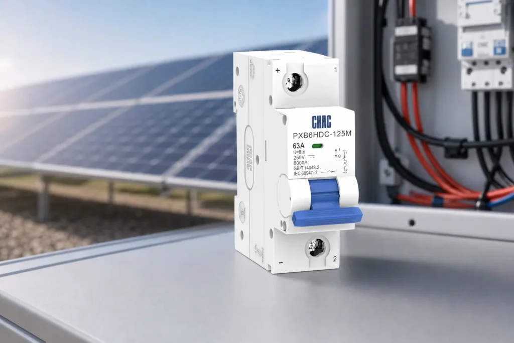
| Funktion | Hauptzweck | What the breaker selection does not prove |
|---|---|---|
| Overcurrent circuit-breaker function | Interrupt overload or fault current within declared ratings and conditions | That all required isolation, earth-fault or arc-fault functions are included |
| Disconnector / isolator | Provide the required isolation function for operation or maintenance | That it provides overcurrent protection or that every breaker is suitable for isolation |
| Surge protective device (SPD) | Limit specified transient overvoltage conditions as part of a coordinated design | That the breaker limits surges |
| Residual-current or earth-fault function | Detect the specified leakage or earth-fault condition | That ordinary overcurrent protection detects every earth fault |
| Arc-fault function | Detect and act on covered arc-fault signatures when explicitly provided | That a standard DC overcurrent breaker includes arc-fault detection |
A breaker may also provide switching or isolation capabilities when the exact product is designed, marked and installed for them, but the word “breaker” alone is not evidence. Treat the one-line diagram as the functional map: show overcurrent protection, isolation points, SPDs, residual-current or earth-fault measures and arc-fault equipment as separate items unless the selected product documentation explicitly combines them.
Opening a device also does not prove that every nearby terminal is de-energized. For US panelboards investigated for interconnected power sources under NEC Article 705, UL Solutions’ Panelboard Application Guide describes warnings that both line and load terminals may remain energized with the disconnect open. This is scoped US panelboard guidance, not a DC-breaker rating or a wiring instruction for IEC products. The applicable installation rules and qualified-person isolation procedure must account for all sources.
Which PV and Circuit-Breaker Standards Apply?
IEC 62548-1:2023+AMD1:2025 CSV addresses the design requirements for PV arrays, including DC wiring, electrical protection devices, switching and earthing provisions. The 2025 consolidated edition includes revisions concerning isolation, cables, earth-fault arrangements, bifacial and non-optimal orientation conditions, and arc-flash provisions. It excludes energy storage devices and load or distribution networks, so it must not be stretched into a battery-breaker approval method.
IEC 60364-7-712:2025, the third edition, covers selection and application requirements for PV electrical installations from the modules to the connection point. Its 2025 changes include battery-related installation requirements and direct battery, DC bus and DCU provisions. This installation scope is distinct from IEC 62548-1’s PV-array design scope; neither reference by itself establishes the rating or permitted wiring of a specific breaker.
IEC 60947-2:2024 covers circuit-breakers up to 1,500 V DC within its stated scope. That upper scope limit is not a rating for a specific catalog number, and citing the standard is not the same as demonstrating product certification, an installation voltage, breaking capacity or a permitted wiring configuration. Procurement should request the exact model declaration and test/documentation basis relevant to the destination market and intended use.
Non-compliance has a commercial cost beyond the breaker itself: design resubmittals, delayed inspection, panel rework, rejected substitutions and unclear liability after a field event. The project team should identify the destination rules, intended circuit role and marketing claims before asking a supplier to confirm documentation. No article can certify a project or product.
Which Documents Support a Solar DC Breaker Selection?
Use the following sequence to turn engineering data into a reviewable request:
- Freeze the one-line diagram and label the boundary as PV array, battery branch, converter interface or DC distribution.
- Attach the voltage, current, conductor and fault-current inputs, including temperature and installation assumptions.
- State the grounding arrangement, conductors to be opened, normal and fault-current directions, and required isolation points.
- Request the exact catalog number, DC ratings, breaking capacity for required fault directions, polarity markings, approved series-pole diagram, terminal limits, derating information and installation instructions.
- Compare the supplier’s connection diagram with the project one-line; record any separate disconnector, SPD, earth-fault, residual-current or arc-fault equipment.
- Hold substitutions until the panel builder or responsible engineer repeats the same documented checks for the replacement model.
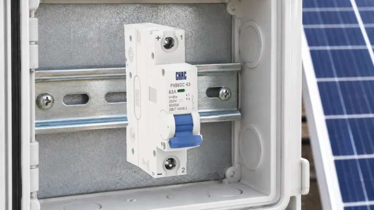
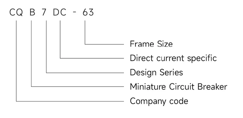
For product screening, CHAC’s DC-Schutzschalter category provides a starting point, while the CQB7DC-63 DC miniature circuit breakers page is a model-family route for a more specific document request. These pages do not replace the project study or the exact product instructions, and no bidirectional interrupting capability is established here.
The lowest purchase price is not necessarily the lowest project cost. Compare documentation completeness, fit with the approved connection, coordination evidence, substitution control and commissioning effort. An inexpensive device that triggers a redesign or cannot be traced to the approved diagram can cost more than the apparent unit saving.
What Else Should Buyers Check About Solar DC Breakers?
What type of DC breaker is needed for solar panels?
Use a breaker with published DC ratings that cover the circuit’s cold-temperature maximum voltage, continuous design current and prospective fault current, with the required polarity and pole arrangement. The exact type also depends on conductor protection, array architecture, grounding, installation conditions and required switching or isolation functions; confirm all of these against the product instructions and destination rules.
How do I calculate the correct size circuit breaker for solar panels?
First derive maximum PV voltage from the series string and the module’s temperature data at the project’s lowest design temperature. Then determine design current using the applicable PV design method, verify the conductor limit, evaluate reverse-current and fault contributions, and select a device whose published DC ratings and connection instructions cover every input. Do not apply a universal multiplier without the governing standard, code and source data.
Does a non-polarized DC breaker automatically work on a battery circuit?
No. A non-polarized description does not establish the required fault-interruption duty, and a battery-connected circuit may have different available fault current and current paths from a PV string. Confirm the exact model’s DC voltage, breaking capacity, permitted wiring and coverage of every required fault direction before using it at that location.
What size circuit breaker for 400w solar panel?
A 400 W label is insufficient to select a breaker. Two 400 W modules can have different open-circuit voltage, short-circuit current and temperature behavior, and series or parallel connections change the circuit conditions. Obtain the module data sheet, string layout, minimum design temperature, conductor details and fault-current paths before sizing.
Does a DC breaker replace a PV disconnector, SPD or arc-fault device?
Not by default. Overcurrent protection, isolation, surge protection, residual-current or earth-fault protection and arc-fault detection are different functions. Treat each separately unless the exact product documentation explicitly declares and supports the combined function for the installation.
Which Sources Define These Selection Boundaries?
- IEC, IEC 62548-1:2023+AMD1:2025 CSV—Photovoltaic (PV) arrays—Part 1: Design requirements.
- IEC, IEC 60364-7-712:2025—Low-voltage electrical installations—Part 7-712: Requirements for special installations or locations—Solar photovoltaic (PV) power supply installations.
- IEC, IEC 60947-2:2024—Low-voltage switchgear and controlgear—Part 2: Circuit-breakers.
- Schneider Electric, Fundamental characteristics of a circuit-breaker, Electrical Installation Guide, last edited 5 August 2026; AC examples remain limited to their stated context.
- UL Solutions, Panelboard Application Guide, interconnected power-source markings; US panelboard scope.
- c3controls, AC MCBs vs DC MCBs: The Difference is More Than a Letter!; Series 1100 example only.
The dependable rule is to approve the breaker from the documented circuit and connection, never from wattage or a familiar front-label number alone. Start with cold maximum PV voltage and the actual source boundary, then check conductor protection and the available fault current through each device. Match those conditions to the model’s DC voltage, permitted poles, terminal orientation and interruption documentation. Normal reverse current and reverse fault interruption are separate checks, and an open handle is not evidence that all sources have been isolated. CHAC’s category and model-family pages can help identify products for document review; approval still depends on the exact model evidence and applicable installation rules.
When your one-line, source data and fault-current review are ready, send the required ratings, pole and polarity arrangement, installation conditions and target-market documentation needs through CHAC Electric’s contact team for product matching and a document check.