A panel quotation can list breaker current ratings yet leave the decisive question unanswered: how much fault current can reach that panel? Before comparing devices, buyers need a traceable electrical model, not just the transformer nameplate or the building’s connected load.
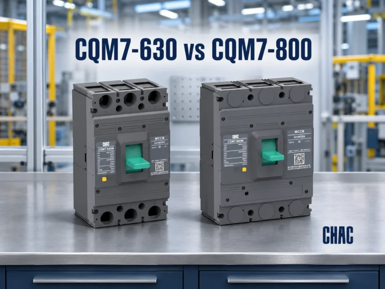
A short circuit current calculation needs source strength, system voltage, transformer impedance, conductor details, network configuration and contributions from connected generation or rotating machines. Calculate at each relevant equipment location, then compare the results with documented device and assembly ratings under matching conditions. When calculating prospective short circuit current, distinguish the maximum used for breaking capacity from the minimum used to check whether protection will operate. For an example of how the result is used in a purchase decision, compare the two CQM7 frames offered at 630 A.
Which source and network data should you collect first?
Start with an up-to-date single-line diagram showing supplies, transformers, feeders, ties and equipment locations. Record normal and credible alternative operating configurations. A calculation based on one supply arrangement may not represent operation with parallel transformers or local generation.
| Entrée | Que demander | Pourquoi c'est important |
|---|---|---|
| Utility supply | Maximum and minimum fault levels, reference voltage, connection point and impedance or X/R information | Defines upstream source strength and asymmetry |
| Transformer | kVA, voltages, percentage impedance, winding connection, taps and available impedance tolerances | Defines current base, impedance and fault paths |
| Feeder | Length, conductor size, material, parallel runs and installation arrangement | Defines resistance and reactance to the fault point |
| Other sources | Machine or converter data and operating configurations | Captures contributions omitted by a utility-only model |
For unbalanced and earth faults, collect grounding arrangements and applicable sequence impedances as well. Missing data should be identified as assumptions for engineering review, not silently replaced by typical values.
IEC 60909-0:2016 describes calculation procedures for balanced and unbalanced short circuits in low- and high-voltage three-phase AC systems. Its scope does not establish any particular product’s certification or cover every DC application.

What does the short circuit current formula actually represent?
A simplified three-phase short circuit current equation is I = U / (√3 × |Z|), where U is line-to-line voltage and Z is the equivalent per-phase impedance to the fault. This represents a balanced bolted fault using a simplified equivalent circuit; a formal study applies the chosen method’s voltage factors, corrections and fault-specific models.
At transformer terminals, a preliminary estimate is Ifault ≈ Irated × 100 / Z%, with Irated = S / (√3 × U) when S is in VA and U in volts. This assumes an effectively infinite upstream source and neglects downstream impedance and other contributions. Higher kVA increases rated current at unchanged voltage; higher percentage impedance reduces this estimate at unchanged kVA.
Cable resistance and reactance add to the network impedance. Length, cross-section, material, temperature and conductor arrangement therefore affect the result. A remote panel can have a lower fault level than the transformer terminals, but minimum fault current also matters when checking protective operation.
Motors can briefly feed a fault; generators and converter-based sources require their own contribution models. Distinguish initial symmetrical current, peak current and current at the relevant interruption time. A single current value does not answer every equipment-duty question.
How should buyers turn calculation results into equipment checks?
Available fault current describes the installation at a location. A panel’s short-circuit rating describes documented equipment capability under stated conditions. A breaker’s interrupting rating alone does not establish the rating of the complete assembly.
| Décision | Required input or evidence |
|---|---|
| Breaker comparison | Local fault duty, voltage, AC/DC system and exact variant’s breaking-capacity documentation |
| Assembly review | Declared short-circuit characteristics and any specified upstream protective-device conditions |
| Révision de la protection | Maximum and minimum fault results, trip characteristics and coordination study |
| Quotation release | Equipment-location schedule, operating scenarios and unresolved assumptions |
IEC 61439-1:2020 provides general rules for low-voltage switchgear and controlgear assemblies; citing it is not evidence that a quoted panel has been verified.
Utilisez le Gamme CHAC MCCB to discuss circuit type, protection functions and voltage-specific Icu/Ics documentation, or the Gamme CHAC MCB to compare documented breaking capacities. These are consultation starting points: exact variants and assembly conditions still require confirmation.

Foire aux questions
What source data are needed to calculate prospective short-circuit current?
Request utility maximum and minimum fault levels at the connection point, voltage, impedance or X/R information, and the applicable supply configuration. Add transformer, feeder, grounding and local-source data to model the downstream network.
How do transformer kVA and percentage impedance affect a fault calculation?
At fixed voltage and percentage impedance, larger kVA raises the transformer-terminal estimate. At fixed kVA, greater percentage impedance lowers it. Upstream impedance, tolerances and other sources can change the actual result.
Why must cable length and size and material be included in the calculation?
They determine feeder impedance rather than merely load-carrying capacity. Include parallel conductors and arrangement because reactance also matters; temperature assumptions affect resistance and minimum-fault checks.
When should motor and generator contributions be considered?
Include them when they can feed the fault in a studied operating configuration. Obtain machine characteristics, converter fault-response data and contribution duration rather than treating all connected load as a source.
How does available fault current differ from a panel's short-circuit current rating?
Available current is a calculated site condition; the rating is an equipment capability with defined limitations. Compare compatible quantities and verify any required upstream protection, not just the main breaker’s label.
Why should fault current be calculated at each equipment location?
Each location has a different impedance path and potentially different connected sources. Location-specific results support interrupting-duty, assembly-withstand and protective-operation checks that a transformer-terminal result cannot replace.
When should a short-circuit study be updated after a system change?
Review it when utility strength, transformers, feeders, grounding, generation or operating configurations change. Equipment substitutions also require review if ratings or protective characteristics change; do not assume the previous study remains applicable.
For purchasing, send the location-specific fault results with the voltage, circuit type and assembly requirements. Contactez CHAC to discuss documentation for candidate products, keeping product consultation separate from the engineering study and final equipment verification.