A familiar ampere value is not enough to select a disjoncteur miniature (MCB). Devices with the same current marking can have different voltage ratings, magnetic trip thresholds and short-circuit duties. Interpreting the complete nameplate helps avoid nuisance tripping and unsuitable fault protection. Read the operating conditions first, then check the protection ratings and supporting documentation.
The short answer is to read voltage, AC or DC suitability, poles, rated current, trip curve, short-circuit capacity and the applicable standard together. Icn and Icu are not interchangeable labels, and the quoted capacity must apply at the installation voltage. Match the nameplate to the exact model’s datasheet before specifying or replacing a device.
What do the key MCB nameplate parameters mean?
How do the model and manufacturer identify the device?
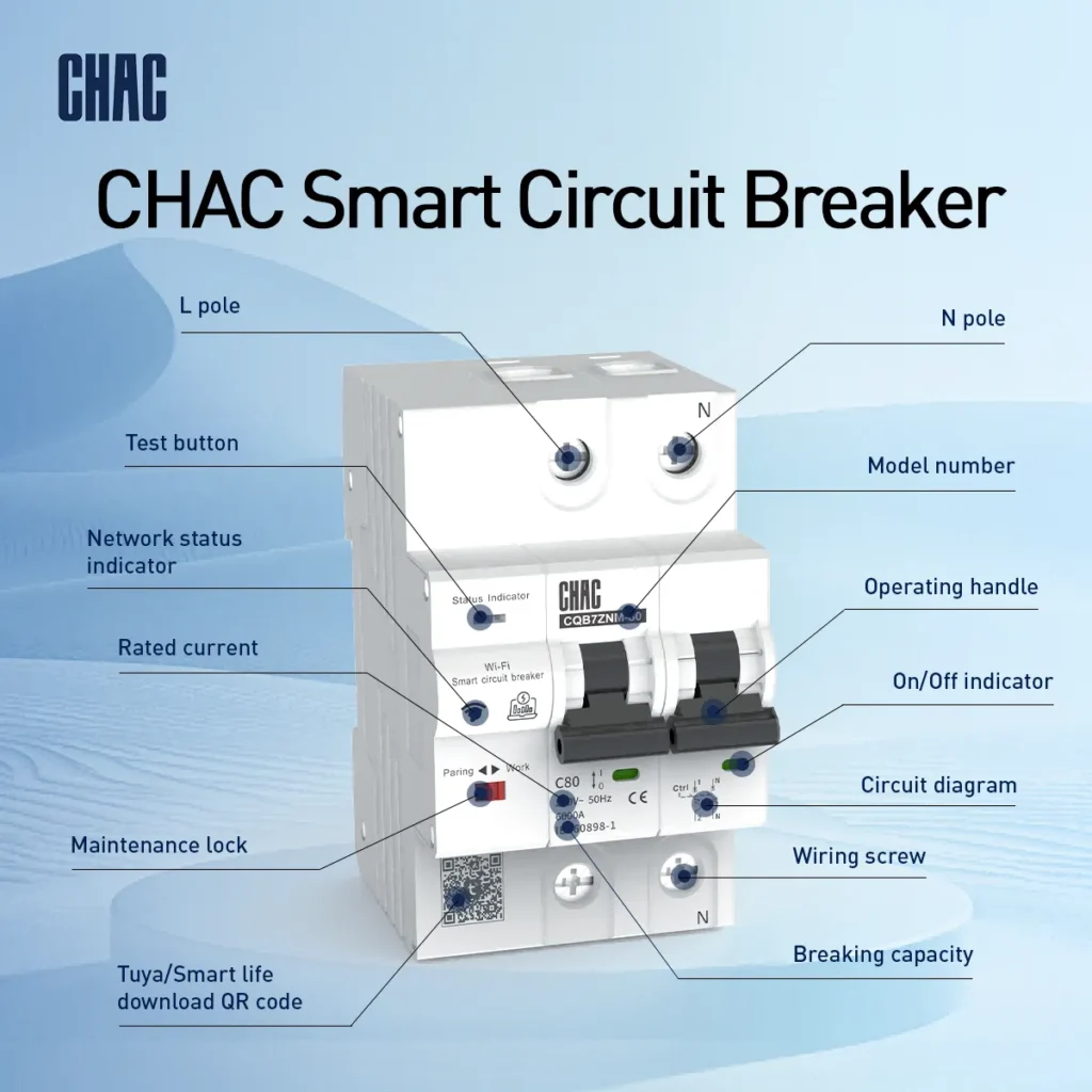
The model number identifies the specific MCB series, while manufacturer information supports traceability. Use both to find the correct datasheet and installation instructions; identification alone does not confirm compliance or certification.
What does rated current (In) tell you?
Le MCB rated current applies under stated reference conditions, not unconditionally at every temperature. Selection must consider connected load characteristics and cable ampacity.
Schneider Electric’s Electrical Installation Guide: Fundamental characteristics of a circuit-breaker defines rated current with reference to manufacturer-stated ambient temperature. In a warm enclosure, obtain the exact model’s derating data. Do not copy another manufacturer’s example or increase the breaker rating without checking conductor protection.
What does rated operational voltage (Ue) mean?
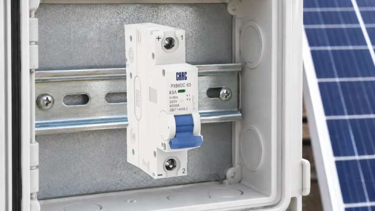
Ue identifies the voltage at which the breaker is designed to operate under normal conditions. Check it with the AC or DC designation, pole arrangement and specified frequency. A rating for one circuit arrangement does not automatically establish suitability for another.
How do Icn, Icu and Ics differ?
pouvoir de coupure du disjoncteur concerns prospective fault current, not the normal current carried by the circuit. The same-looking kA value may refer to a different standard or voltage, so compare like-for-like ratings rather than selecting the largest printed number.
| Marking | Meaning and standard context | What to verify |
|---|---|---|
| Icn | Rated short-circuit capacity used for domestic-type breakers under IEC 60898. | The applicable standard, rated voltage and capacity for the exact device. |
| Icu | Rated ultimate short-circuit breaking capacity under IEC 60947-2. | The rating at the intended operational voltage, not a value quoted for a different supply. |
| Ics | Rated service short-circuit breaking capacity under IEC 60947-2, related to Icu. | The manufacturer’s declared Ics value or relationship to Icu at that voltage. |
Le Schneider Electric guide’s short-circuit rating explanation, last edited 5 August 2026, distinguishes these terms and describes standardized test sequences. Match the relevant rating to the prospective short-circuit current. Higher capacity does not by itself improve overload protection or prove selectivity.
Do B, C and D curves mean faster or better protection?
B, C and D identify different instantaneous magnetic trip thresholds, not a ranking of protection quality. A lower threshold may cause nuisance trips during inrush; a higher threshold still needs sufficient fault current to meet required disconnection times. Choose from the manufacturer’s time-current curve and circuit conditions, not a claim that one letter is always faster or better.
Do standards and conformity markings prove certification?
A printed IEC standard number is not independent certification by IEC. The European Commission’s CE marking guidance explains that CE is a manufacturer’s declaration of conformity with applicable requirements, not safety approval by the EU or another authority. CE alone therefore does not prove third-party certification.
Where a supplier claims UL certification, check the exact model and identifiers against the relevant record. UL Solutions’ Product Sourcing and Certifications Database supports searches using file numbers and category control numbers. A certificate for another series does not establish the supplied model’s scope.
What do terminal markings and connection diagrams show?
Terminal markings and connection guides help prevent installation errors. Verify any polarity or line/load requirements and pole functions against the installation instructions. Do not infer neutral protection or DC connections from the number of poles alone.
How should you read an MCB nameplate in the right order?
Start with the system, then move to the protection duty. Read the MCB nameplate markings in this order: voltage and frequency, number of poles, rated current, tripping curve, rated short-circuit capacity, and the applicable product standard. This prevents a common buying error: choosing a familiar ampere value before confirming whether the device is suitable for the installation.
- Confirm the voltage and circuit arrangement. Check the AC or DC designation, phase arrangement and pole configuration against the design. A current rating alone does not prove that a breaker is suitable for a DC circuit or for switching the neutral.
- Match rated current to the protected conductor and load. Verify conductor ampacity, installation method and ambient conditions rather than treating the handle’s number as a cable-size recommendation.
- Choose the tripping curve from inrush behaviour. Use the manufacturer’s time-current data and the actual load, especially for motors, transformers, LED drivers and long cable runs.
- Check the fault level at the installation point. The marked breaking capacity must suit the prospective short-circuit current under the governing standard and at the intended voltage.
What can the nameplate not tell you by itself?
A nameplate does not replace the coordination study, wiring diagram or local installation rules. It normally cannot tell you whether the upstream and downstream devices will achieve selectivity, whether a neutral must be switched, or whether an accessory is compatible with a particular series. For panel documentation, pair the marking with the manufacturer’s datasheet and the relevant MCB symbol on the single-line diagram.
What questions do buyers ask about MCB markings?
What does a B16 or C20 marking mean?
The letter identifies the tripping characteristic and the number identifies rated current in amperes. Verify the complete nameplate, voltage, poles and short-circuit rating before treating the marking as a selection.
Is a higher kA value always the better choice?
No. The kA marking must be matched to the installation fault level, rated voltage and product standard. A higher value can be unnecessary for one location and still insufficient for another if the system study is wrong.
What does Icu mean on a breaker?
Icu means rated ultimate short-circuit breaking capacity in the IEC 60947-2 context. Read it at the specified operational voltage and do not substitute it directly for an IEC 60898 Icn value.
What does Ics mean on a circuit breaker?
Ics means rated service short-circuit breaking capacity under IEC 60947-2. Check it separately in the manufacturer’s data for the relevant voltage. Do not assume that it equals Icu merely because one kA value is prominent on the device.
What is the symbol for a circuit breaker?
Use a drawing’s legend to identify its circuit-breaker symbol. Product markings serve different purposes: the Schneider Electric guide describes a front-face symbol for a circuit-breaker suitable for isolation. That suitability marking is not a general circuit-breaker label or certification logo.
For additional illustrations, consult the CHINT nameplate guide and the Schneider Electric MCB selection guide. Final selection remains project- and jurisdiction-specific.
What should you verify before specifying the breaker?
Understanding these parameters enables electrical professionals to make informed decisions for residential, commercial and industrial applications. The important distinction is between what a marking identifies and what the complete documentation establishes. Confirm the supply and circuit arrangement first, match current and trip behaviour to the conductor and load, then verify fault duty at the installation voltage. Check the exact model’s ambient derating, instructions and any claimed certification scope before approval. Proper selection helps avoid nuisance trips while keeping the circuit’s protection requirements in view. For application-specific MCB selection guidance, consult CHAC‘s technical specialists and request the relevant model documentation rather than assuming that every product in a range carries the same ratings or certification.