A relay specified only by motor current can still produce the wrong starter behavior. The motor may need a longer acceleration time than the selected trip characteristic permits, or a reset may restore a maintained command and restart machinery unexpectedly. The important questions concern starting duty, thermal condition and control logic together. This guide explains what a motor-control specification should say about current setting, trip class and reset behavior, with documented product examples. It also separates overload protection from short-circuit protection, so a complete starter is not reduced to a relay dial setting and an unchecked promise of compatibility.
The short answer is to select the thermal overload relay range around the motor’s rated current, then verify its trip characteristic against starting duty and thermal limits. Choose reset behavior only after reviewing the restart sequence. A relay becoming ready again does not necessarily mean the motor should run. Manufacturer test conditions matter: CHAC’s CQR2 table specifies a cold-state test at 7.2 times setting current, whereas a Schneider NEMA trip-class FAQ uses 600%. Those different reference conditions must not be merged into a universal timing claim.
Which motor data controls the current setting?
Identify the motor’s nameplate current at its actual supply voltage and connection. Include starting method, expected acceleration time, load and restart frequency. A kilowatt value alone is not an adequate setting instruction.
Choose a relay range that contains the required setting, then apply the manufacturer’s installation guidance. Location matters: a relay in a star-delta arrangement cannot be set by blindly copying a line-mounted relay setting. Record its position in the starter and have the responsible designer approve the interpretation.
How should trip class be matched to starting duty?
Trip class describes response under specified test conditions, not a guarantee of the same time at every overload. Compare the actual start profile with the selected time-current curve and the motor’s permissible thermal duty. Raising the class solely to hide a difficult start can leave a different protection problem unresolved.
| Decision | Information needed | Common mistake |
|---|---|---|
| Current range | Rated motor current and relay location | Choosing from motor power alone |
| Trip characteristic | Start current, duration and thermal limits | Treating a class number as every trip time |
| Frequent starts | Hot/cold state and duty cycle | Using only a cold-start curve |
| Fault protection | Exact coordinated fuse or breaker | Expecting the relay to clear a short circuit |
Schneider Electric’s NEMA trip-class explanation refers to class 10/20/30 at 600% current and explicitly concerns North American products. Use that as an example of why the test basis must accompany a class designation, not as an IEC-wide test definition.
What does reset change in the control circuit?
Automatic reset can restore the relay’s control-contact availability after the thermal condition permits it. If a two-wire run command remains present, the complete circuit may then restart the motor. With other command logic, reset may only make a subsequent deliberate start possible.
Define reset and restart separately. A manual reset is not, by itself, proof that unexpected restart is impossible: maintained controller outputs and parallel command paths still need review. Where unexpected motion presents a hazard, establish the appropriate restart controls through the machine risk assessment.
Why is reset time not a fixed waiting period?
Schneider’s LRD reset-time FAQ, modified August 11, 2026, explains that bimetal reset depends on the trip, hot/cold state and ambient conditions. The sensors must cool and return before reset is possible. That is model-specific guidance, not a fixed timer for every thermal relay.
Repeated trips deserve investigation. Review actual motor current, phase condition, mechanical load, cooling and starter behavior before resetting again. Do not bypass protection or enlarge the setting to get an unexplained fault back into service.
Which starter combinations need verification?
The contactor, relay and upstream short-circuit device form a combination. Obtain the exact mounting and electrical references, voltage and documented coordination conditions. A relay with a suitable current range is not necessarily mechanically compatible with the proposed contactor.
For a technology comparison, see electronic versus bimetallic overload relays. Diagnostic or remote-reset requirements should be explicit; do not assume every electronic relay or every accessory supplies them.
What does the CQR2 product record establish?
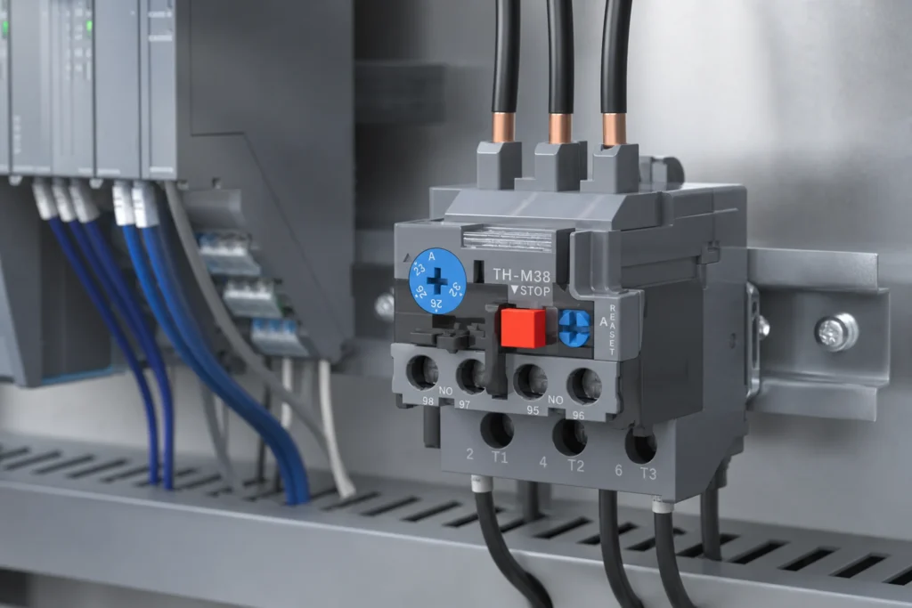
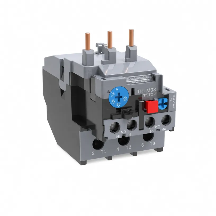
CHAC’s thermal overload relay page lists CQR2-25, CQR2-38 and CQR2-95, manual/automatic reset, phase-loss protection and 1NO+1NC contacts. Its cold-state 7.2-times-setting-current test specifies 2s < trip time ≤ 10s. Other test rows have different initial conditions; one row is not the entire time-current curve.
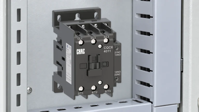
The page also provides adjustment ranges and plug-in contactor references. Review the corresponding AC contactor documentation for the selected pair, rather than assuming every CQR2 fits every CQC6 frame. Settings and reset-mode changes belong to the de-energized procedures in the product instructions.
What should commissioning document?
| Enregistrer | Purpose |
|---|---|
| Motor and starter identifiers | Connect the setting to the actual installation |
| Setting and trip characteristic | Retain the approved protection basis |
| Reset mode and command logic | Explain restart permissions after a trip |
| Authorized functional tests | Verify contacts and sequence without creating a live fault |
Foire aux questions
How do I manually reset an overload relay?
Follow the selected relay’s instructions after investigating the trip and allowing its thermal condition to permit reset. Do not treat reset as fault removal.
Is class 10 always a ten-second delay?
No. The designation refers to defined test conditions; actual trip time follows the current and initial thermal condition.
Does automatic reset always restart the motor?
No. The remaining command and interlock logic determines whether coil energization resumes.
Does the relay replace short-circuit protection?
No. Use the documented upstream protective-device combination for that duty.
Can repeated trips be solved by raising the current setting?
Not without a justified design review. Investigate load, phase condition, starting duty and the installed setting first.
Is the test button a complete calibration test?
No. It can check specified mechanism/contact functions, but does not prove the complete current-time response or starter coordination.
Références
- Schneider Electric: NEMA overload relay trip classes and test conditions.
- Schneider Electric: LRD thermal overload relay reset time, modified August 2026.
- Rockwell Automation: Low Voltage Motor Protection, motor-circuit and overload-protection discussion.
A good motor-control specification ties the relay to the motor, start profile and complete starter sequence. Establish the required setting and characteristic first, then confirm the contactor and short-circuit device, and finally define what reset permits the control system to do. Keep cold-state tests separate from hot-restart behavior and a functional test button separate from calibration evidence. These distinctions make the specification more useful than a list of nominal ratings. CHAC’s CQR2 and CQC6 records can support a model-specific review; unresolved coordination and restart behavior still require engineering approval. Contact CHAC with the motor data, starter diagram and reset requirement.