A disconnect switch is selected for an isolation or switching duty defined by the single-line diagram, not by the product photograph. The key questions are what must be isolated, whether the switch will break a load, what upstream protection is present, and how the operator will verify and lock the isolation.
Separate isolation, switching and protection before comparing models
Write the circuit role first, then record the operating voltage, current, load type, utilization category, duty frequency, short-circuit conditions and enclosure position. The isolating-switch range is a starting point for model review, not a substitute for the circuit design.
What isolation point must the switch create?
Mark the conductors to be opened, the upstream source and the location where maintenance personnel will operate the device. A visible handle is useful only when the selected device and installation arrangement provide the isolation evidence required by the project.
Which circuit and enclosure inputs should be on the drawing?
Include system voltage, current, AC or DC duty, load category, ambient conditions, mounting format, cable entry and access restrictions. A small control isolator cannot be promoted to a feeder disconnect simply because the dimensions look similar.
How should utilization and switching duty be written?
State whether the device is for isolation, normal load switching, emergency operation or a combination. Verify the utilization category and conditional short-circuit rating in the selected documentation. IEC 60947-3 dan IEC 60947-2 address different device roles.
Where do locking and service procedures change the choice?
If the safety plan requires padlocking, door interlocking or a handle that remains accessible with the enclosure closed, put that requirement on the drawing. Confirm the exact interface and the allowed accessory before approving a sample.
What should a buyer send to a supplier?
Send the single-line diagram, load and duty description, ratings, pole count, mounting constraints, lockout requirement, upstream protection and requested document set. This keeps a quotation focused on the actual isolation boundary instead of a headline current.
Which CHAC route supports the first shortlist?
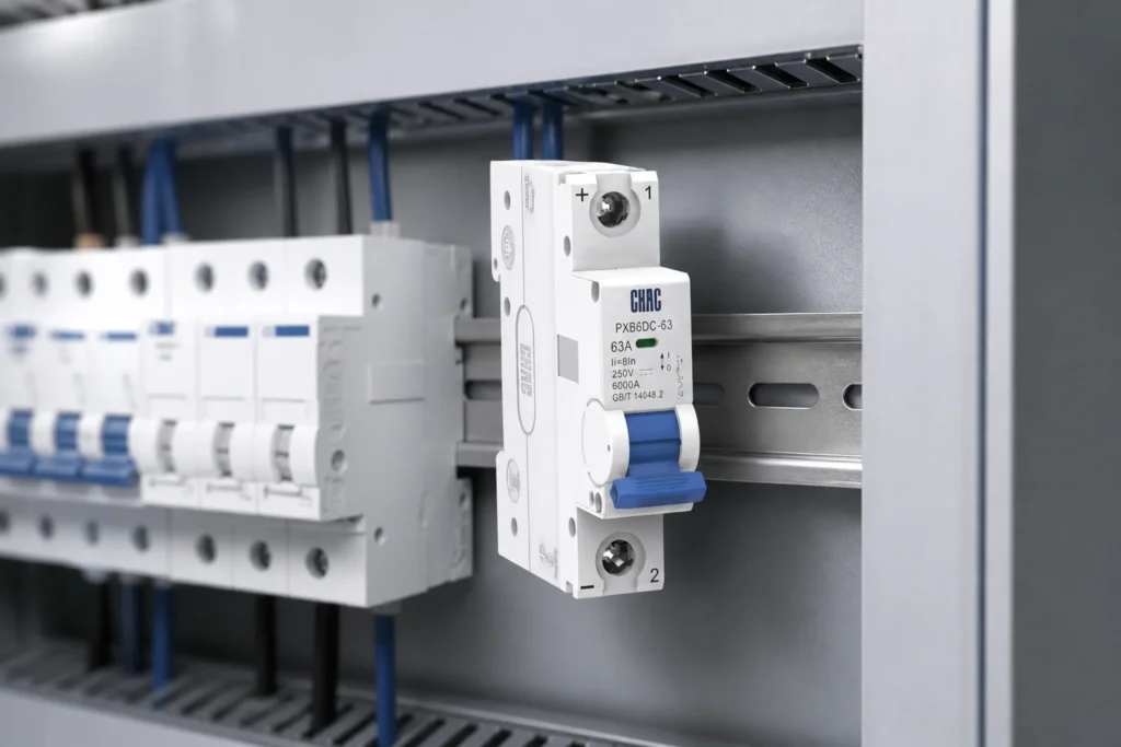
Compare the PXD6 isolator information with the project’s required duty, then confirm the exact model, terminals and installation instructions. Related DC switching products need a separate DC voltage and arc-interruption review.
Where must the final decision return to the designer?
Return to the responsible designer when the circuit has a high prospective fault current, a DC source, emergency-stop implications or a local isolation rule that is not clear from the product data. Isolation is not a replacement for overcurrent protection.
The useful output is a documented load-break isolation boundary: what opens, under which duty, with which upstream protective device and how the operator verifies the safe state.
For the relevant product family, review our disconnect switch range.
Pertanyaan yang sering diajukan
Is every isolating switch suitable for load breaking?
No. Switching and isolation duties are model-specific and must be confirmed in the selected documentation.
What drawing defines the isolation point?
The approved single-line diagram and panel layout define where isolation is required and which conductors are included.
Can a miniature isolator replace a larger feeder disconnect by appearance?
No. Circuit role, ratings evidence, and project rules control the choice.
When should padlocking be listed in the RFQ?
List it whenever the project safety plan requires a lockable isolation interface, then verify the selected model supports that interface.
Which documents should a supplier return?
Return the proposed model identification plus the installation and performance documents requested in the RFQ.
How does this differ from a DC PV isolator review?
DC PV and battery isolation has different circuit and product-route questions; keep that review on its own project inputs.