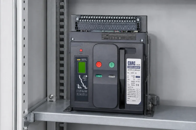
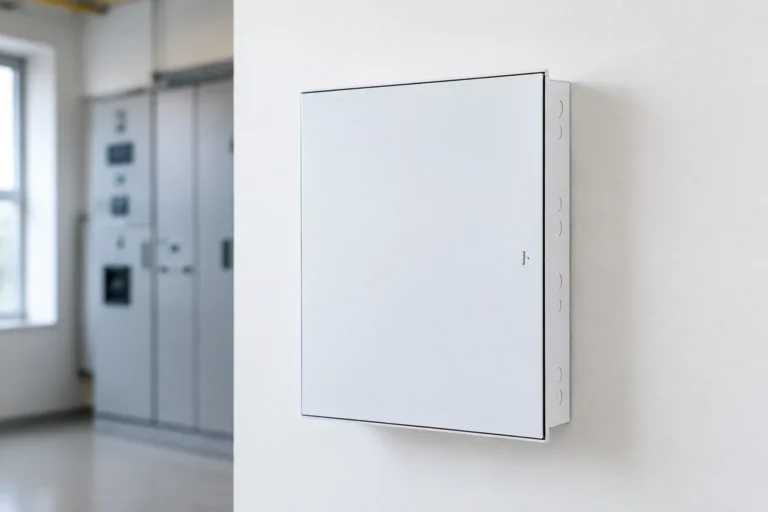
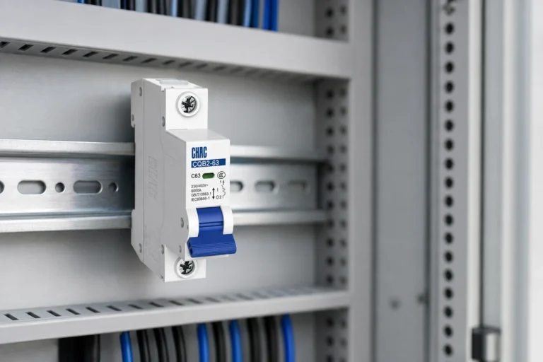
When a facilities engineer in Kuala Lumpur encountered repeated shutdowns on a 400/230 V tenant distribution board, he replaced the incoming breaker with a larger frame. Within seconds of the next downstream fault, the whole floor went dark again. Review of the one-line diagram, fault study, and trip curves reversed the diagnosis: the problem was not a defective breaker or ampere rating alone, but incorrect fault-duty and coordination assumptions.
Resumo: A main circuit breaker protects and isolates a defined distribution section, yet its rated current is only one selection input. IEC 60947-2 and UL 489 address breaker performance, while the installed device must also have an interrupting rating at least equal to the available fault current at its location. Confirm the load calculation, fault level, time-current behavior, installation environment, and assembly documentation before approving a model.
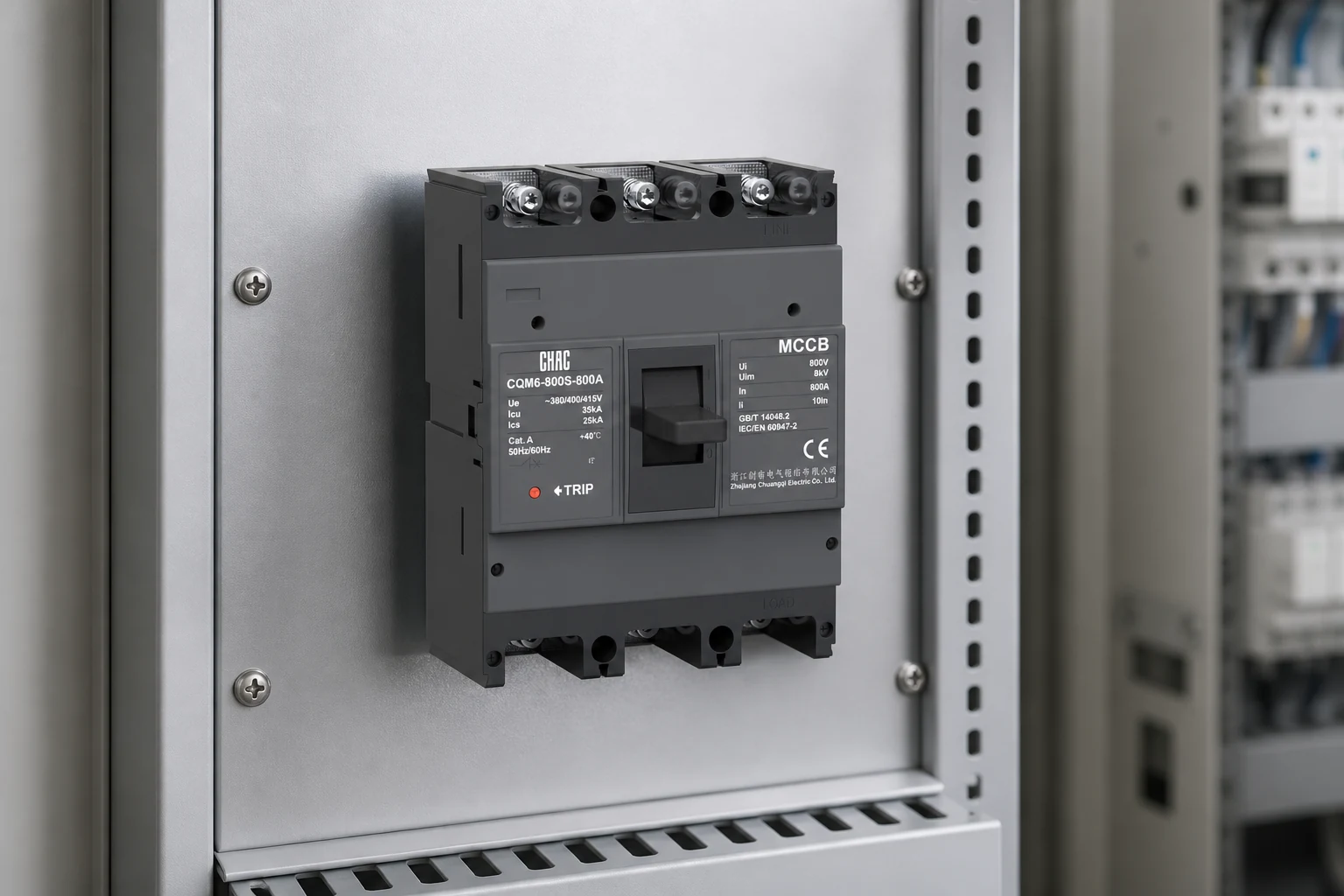
A main circuit breaker is usually the first overcurrent device for a panel, switchboard, or major sub-distribution section. It carries normal current, opens under defined fault conditions, and commonly provides local isolation. Line-side parts can remain live after it opens.
What the main circuit breaker protects
The device protects conductors, bus, and equipment on its load side. Thermal-magnetic trips provide basic overload and instantaneous protection, while electronic trips can add adjustable long-time, short-time, instantaneous, and ground-fault functions. IEC 60947-2 defines performance requirements for low-voltage circuit breakers; UL 489 covers molded-case circuit breakers and related enclosures in North America.
Available fault current and breaker interrupting rating answer different questions. The first is the prospective current the system can deliver at a point; the second is the maximum fault current the breaker is evaluated to interrupt at a stated voltage. Illustratively, 22 kA at the incoming terminals rules out an 18 kA breaker, even for a 400 A load. NEC 110.9 addresses adequate interrupting ratings; IEC projects should compare calculated duty with Icu and Ics data rather than treat frame current as fault capacity.
Selective coordination adds a time dimension: the branch device nearest a fault should open before the main where the design requires it. Engineers should overlay manufacturer time-current curves and check long-time pickup, short-time delay, instantaneous regions, and any zone-selective interlocking. A higher interrupting rating does not create selectivity; curve overlap can still turn one feeder fault into a building-wide outage. NFPA 70 requires selective coordination for certain emergency, legally required standby, and critical operations systems, but not every ordinary board.
How main breaker location changes the requirement
The main breaker location may be at service equipment, a switchboard supplied from separate service disconnecting means, or a downstream panel. These labels are not interchangeable. NEC 230.70 requires a service disconnect to be readily accessible and outside or inside nearest the service-conductor entrance; a “main” in a subpanel is normally a feeder disconnect. Local codes and the adopted edition control.
Position also changes fault duty. A device close to a transformer or generator may see more fault current than one several cable runs downstream. Retrofit teams should recalculate when transformer impedance, conductor length, parallel feeders, or utility data changes. NEC 110.24 requires available fault-current marking on covered service equipment; the engineering record should show the basis and date.
Access remains a design input. The operating handle should be identifiable and compatible with the site’s lockout procedure, with working space and enclosure arrangements governed by the applicable installation rules. Incoming-device changes can also alter the scope of an electrical panel replacement cost review. For export projects, confirm whether the document set uses low voltage and high voltage terminology before comparing product families.
How to make a main breaker selection
Begin with a documented load calculation, not a nameplate sum. In North America, the adopted NFPA 70 Article 220 method and continuous-load rules set the basis; IEC projects should use the applicable IEC 60364 method and local diversity assumptions. Record voltage, frequency, phases, neutral treatment, demand, inrush, harmonics, and credible future load. Verify that conductors and bus remain protected at the chosen settings.
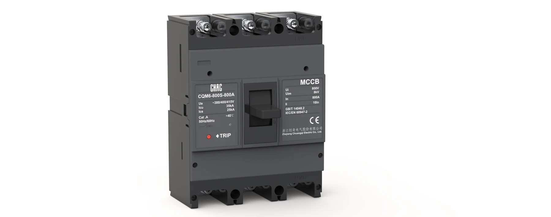
For many commercial incomers, a MCCB main circuit breaker provides a compact solution when its current range, adjustment capability, and interrupting rating fit the study. At higher currents, or where maintainability and short-time coordination are stronger priorities, an air circuit breaker for a main incomer may offer a more suitable operating and accessory platform. The choice should follow verified curves and application data, not a device-type shortcut.
| Main-breaker option | Typical fit | Protection behavior | Lifecycle consideration |
|---|---|---|---|
| Thermal-magnetic MCCB | Smaller commercial incomers and straightforward feeders | Fixed or limited adjustable overload and instantaneous protection | Compact where coordination requirements are modest. |
| Electronic-trip MCCB | Boards needing finer setting control | Adjustable long-time, short-time, or instantaneous functions by model | Can improve coordination without moving to a larger device class. |
| Air circuit breaker | Main switchboards and higher-current incomers | Broad setting, indication, communication, and interlocking options by model | Higher initial complexity may be justified where uptime and serviceability matter. |
Ambient conditions can change the result. Catalogue ratings assume stated conditions; enclosure temperature, grouping, altitude, ventilation, and terminal limits can require derating. Use manufacturer tables for the exact breaker and mounting arrangement, then check the assembly. Oversizing the frame for heat without reviewing conductor protection and trip settings can move the risk elsewhere.
Which records close the specification
Breaker certification does not establish the short-circuit rating of the complete board. UL 489 evidence applies to the breaker covered by that evaluation; the assembly must carry its own applicable SCCR or short-circuit withstand documentation. Likewise, IEC 61439 addresses low-voltage assemblies, while IEC 60947-2 addresses the breaker. A 65 kA breaker inside a board is not proof that the assembled system has a 65 kA rating.
| Selection checkpoint | Documented evidence | Decision risk |
|---|---|---|
| System match | Voltage, frequency, poles, neutral arrangement, and one-line diagram | A correct ampere rating cannot correct the wrong system configuration. |
| Load duty | Demand calculation, continuous-load treatment, inrush, and growth allowance | Nameplate totals can cause unnecessary oversizing or missed operating duty. |
| Fault duty | Dated available-fault-current study and breaker interrupting data at system voltage | This is a safety pass-or-fail check at the installed location. |
| Coordenação | Time-current curves, settings schedule, and selectivity tables | Unreviewed overlap can extend a local outage to the full board. |
| Ambiente | Ambient, altitude, enclosure, mounting, and manufacturer derating data | Field conditions can reduce carrying or tripping margin. |
| Assembly context | SCCR or withstand rating, bus limits, accessory list, and applicable reports | Component ratings do not automatically transfer to the complete assembly. |
A practical approval package includes the one-line diagram, load and fault calculations, time-current study, settings, accessories, product data, and assembly rating. Missing evidence can cost more through approval delay, retesting, shutdown, or field replacement than a small purchase-price difference. This is the total-cost case for disciplined main breaker selection.
Main circuit breaker questions
What is the function of a main circuit breaker?
It protects the load-side conductors and distribution equipment against defined overload and short-circuit conditions, and it provides a controlled isolation point. Its protection boundary and trip functions depend on the one-line design and settings.
Where is the main breaker usually located?
It is commonly at the incoming section of a switchboard or panel, but the service disconnect may be a separate upstream device. Confirm the main breaker location against the one-line diagram, service-conductor route, local code, and isolation plan.
How do you size a main breaker correctly?
Use the applicable demand calculation, continuous-load treatment, system voltage, poles, conductor and bus limits, and expected inrush. Then check available fault current, interrupting rating, trip curves, ambient derating, and downstream coordination before fixing the rating.
What is the difference between an MCCB and an air circuit breaker as a main breaker?
An MCCB is generally compact and covers many low-voltage commercial incomers. An air circuit breaker may provide broader adjustment, maintainability, indication, and interlocking options for larger or coordination-sensitive switchboards; exact features depend on the selected model.
Can the main breaker be oversized for future expansion?
Only when the conductors, bus, enclosure, calculated load, and downstream protection remain suitable at the proposed settings. Future capacity should be documented rather than created by increasing the ampere rating alone.
Does switching off the main breaker make the whole panel safe to touch?
No. Line-side terminals, service conductors, control supplies, or adjacent sections may remain energized. Qualified personnel should follow the site isolation plan, lockout procedure, and test-before-touch requirements.
Official references
- IEC, IEC 60947-2, Low-voltage switchgear and controlgear – Circuit-breakers.
- IEC, IEC 61439 series, Low-voltage switchgear and controlgear assemblies.
- NFPA, NFPA 70, National Electrical Code, including rules for services, load calculations, interrupting ratings, and selective coordination.
- UL Standards, UL 489, Molded-Case Circuit Breakers, Molded-Case Switches, and Circuit-Breaker Enclosures.
The durable principle is simple: match the main breaker to the real load, fault duty, location, coordination plan, environment, and assembly evidence.
For a documented comparison of incoming protection options, review the CHAC Electric CQM6 MCCB data alongside the project one-line diagram, fault study, and coordination targets, then contact the team with the required ratings and accessory schedule.