When a panel builder in Shenzhen encountered a contactor that welded during commissioning, the visible failure looked like a poor component. The reversal came after the load was reviewed: a DC circuit had been specified from an AC contactor label, while the coil control and switching duty had never been checked against the application. This representative scenario explains why a contactor can fail quickly even when its headline current appears adequate. The right decision starts with the source waveform, load behavior, coil circuit, utilization category, and required isolation—not with the word “contactor” alone. The sections below show how to distinguish AC and DC contactors, choose among common types, investigate pitting or welding, and document an industrial replacement without inventing a rating.
Resumo: An AC or DC contactor is an electrically controlled switching device for frequent operation of a power circuit; its coil, main contacts, arc-control design, and declared utilization category must match the circuit. IEC 60947-4-1 is the key product-family reference for low-voltage contactors and motor-starters, while IEC 60947-1 provides general rules; neither standard lets a buyer transfer an AC rating to DC. A practical selection record should state nominal voltage, current profile, frequency or DC polarity, load type, coil voltage, duty, short-circuit coordination, and the manufacturer’s test evidence. Verify those facts before ordering, then confirm the wiring and functional test at commissioning.
{{FEATURED_IMAGE}}
What is a contactor, and how does it switch a power circuit?
A contactor uses an electromagnetic or electronically driven coil to move an armature, close power contacts, and carry current to a load. When the coil is de-energized, a spring or equivalent mechanism opens the contacts. Auxiliary contacts provide status or interlocking signals, but they should not be treated as substitutes for the main power poles. This is the practical answer to what is a contactor: it is a controlled switching element whose interrupting and making behavior is declared for a particular electrical duty.
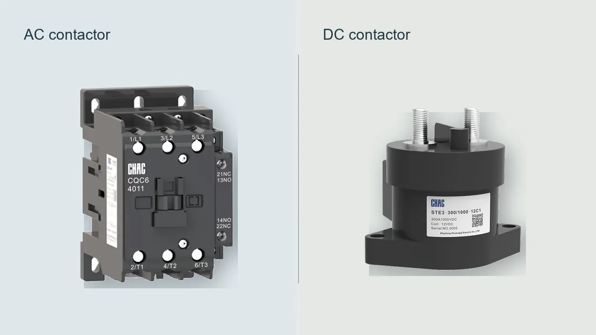
In a motor or power circuit, the contactor normally sits within a coordinated switching and protection arrangement. The upstream protective device limits fault energy; the contactor performs normal switching; an overload or electronic protection function addresses the load’s operating condition where required. IEC 60947-4-1 distinguishes utilization categories such as AC-1 and AC-3, so “the same ampere rating” does not describe the same duty. Ask for the category, poles, making and breaking conditions, and permitted duty cycle.
An AC coil is driven by an alternating control voltage and an AC magnetic circuit; a DC coil is driven by a direct control voltage and normally has different pickup, holding, suppression, and thermal behavior. A 12 V coil is possible in some product families, but it is not a universal standard: the coil marking, tolerance, control supply, and suppression arrangement must be verified from the exact datasheet. The coil voltage does not determine the main-contact rating.
{{INLINE_IMAGE_1}}
How do AC and DC contactors differ in real applications?
The most important difference is the load current and the way an arc is extinguished. AC current passes through a natural zero each cycle, while a DC arc does not receive that periodic zero. A DC design therefore needs an arc-control and contact arrangement declared for the relevant DC voltage, current, polarity, and switching direction. Depending on the design, this may involve arc chambers, magnetic blowout, contact spacing, or a specified pole connection; those details cannot be inferred from the outside of the housing.
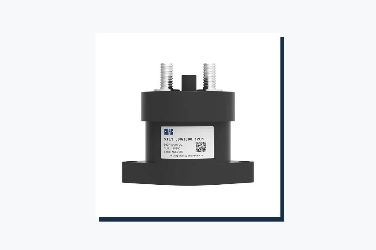
A dc power contactor is selected for the actual DC circuit, not by copying an AC-3 or AC-1 number. Battery storage, photovoltaic strings, electric-vehicle auxiliaries, cranes, and control-power distribution can have different fault levels, inrush, regenerative behavior, and polarity requirements. A dc air break contactor uses air as the interrupting medium and still requires the maker’s declared DC duty. Read the polarity diagram and series-pole instructions before wiring; a seemingly symmetrical terminal layout may not represent a permissible DC connection.
For AC applications, verify frequency as well as nominal voltage, because an AC coil and its magnetic circuit are frequency-sensitive. For DC applications, verify whether a flyback diode, TVS, or other suppression device is built in or must be added; a suppression component can impose polarity and release-time conditions. In both cases, check the coil’s minimum pickup and dropout behavior under the actual control-circuit voltage drop rather than assuming the nominal value will always be present.
IEC 60947-4-1 is a useful anchor for this comparison because it addresses contactors and motor-starters, including operating and test concepts for declared utilization duties. It is a product standard, not permission to combine an arbitrary coil with an arbitrary contact set. The manufacturer’s circuit diagram and test documentation remain the controlling evidence for a specific model.
Which types of contactor suit industrial switching?
The phrase types of contactor can refer to electrical duty, construction, control method, or application. A buyer should classify the load before choosing a catalogue family.
| Contactor type or classification | Where it may fit | Evidence to check |
|---|---|---|
| Contactor de CA | AC motors, heaters, capacitive or mixed industrial loads where the declared utilization category applies | AC voltage, frequency, category such as AC-1 or AC-3, making/breaking duty, coil data |
| DC contactor | Battery, DC distribution, traction auxiliaries, PV-related or other direct-current circuits | DC voltage and current, polarity, arc-control method, pole connection, inrush and fault conditions |
| Air-break contactor | Applications where contacts interrupt in air and the product’s declared duty is suitable | Air-break construction, enclosure, spacing, DC or AC test evidence, environment |
| Reversing or mechanically interlocked set | Forward/reverse motor operation or mutually exclusive power paths | Interlock logic, wiring diagram, transition timing, protection coordination |
| Modular or installation contactor | Panel or building loads with a defined duty and switching frequency | Mounting system, terminal arrangement, permitted load category and service conditions |
Other constructions, including vacuum contactors or electronically controlled variants, should be treated as separate product families rather than assumed equivalents. The relevant test method may include the manufacturer’s IEC 60947-4-1 type-test evidence and routine verification for the exact catalogue reference. A product name alone does not establish short-circuit coordination, endurance, or suitability for a motor, battery, or capacitor bank.
How is a contactor different from a relay?
Searches for contactor vs relay often reduce the distinction to current size, but the engineering boundary is broader. A relay is commonly used for signal or comparatively light control duties; a contactor is designed for switching a power circuit with a declared utilization category, contact arrangement, insulation system, and arc-control behavior. There is overlap in terminology, especially for small DC products, so the model’s declared function and test evidence matter more than the label.
Use contactors and relays together when a control system needs a relay to process a signal and a contactor to switch the load. The relay output must be compatible with the contactor coil, including inrush, suppression, and dropout timing. An auxiliary contact can report “closed” status, but it does not prove that the main poles are carrying current correctly; commissioning should test both the control path and the power path.
| Dimensão de decisão | Contactor | Relay |
|---|---|---|
| Primary role | Frequent switching of a declared power load | Signal logic, isolation, or lower-power switching as declared |
| Arc and contact design | Designed around stated making, breaking, and utilization conditions | Designed around the relay family’s declared load and contact duty |
| Interface de controlo | Coil or electronic drive with defined pickup, dropout, and suppression behavior | Coil, solid-state input, or other interface with its own drive requirements |
| Feedback | Auxiliary contacts can provide status or interlock signals | Contacts can provide logic or control feedback, subject to contact rating |
| Selection risk | Transferring AC, DC, motor, or capacitor ratings without category evidence | Using a signal relay as a power contactor because its contact number looks similar |
IEC 60947-1 general rules and the product-family standard help structure insulation, temperature, marking, and verification questions, but they do not turn every relay into a contactor. Compare the declared test duty, not just the number of poles.
Why do contactor contacts pit, weld, or chatter?
Contact damage is usually a system clue. Pitting can follow repeated arcing, contact bounce, contamination, overload, or a load whose inrush or breaking duty exceeds the declared category. Welding can follow a short-circuit event, a stalled motor, a DC interrupt outside the product’s permitted envelope, or insufficient contact opening after a mechanism fault. Chatter can result from coil undervoltage, a loose control termination, an incorrect frequency, a damaged shading arrangement on an AC magnetic circuit, or a control signal that is not stable.
Do not file or polish contacts as the first corrective action. Record the contactor model, load type, nominal voltage, measured control voltage, switching frequency, protective-device operation, and any visible heat or discoloration. Then compare the event with the manufacturer’s declared utilization category and the IEC 60947-4-1 test basis. The objective is to remove the cause—wrong duty, poor coordination, unstable coil supply, or mechanical damage—not merely to restore a shiny surface.
A fault investigation should also check whether a suppression device was omitted or installed with the wrong polarity, whether a DC load has an inductive kick, and whether auxiliary interlocks permit simultaneous closure of opposing contactors. These checks can prevent a repeat failure without asserting an unverified endurance figure.
How should a buyer select coil voltage and contact rating?
Start with a one-page application record. State the supply’s nominal voltage, frequency or DC nature, phase and pole arrangement, load current profile, inrush, duty cycle, ambient conditions, control-circuit voltage at the coil terminals, and the required isolation or interlock behavior. Then map those facts to the product’s declared utilization category and wiring diagram. The contact rating is not a free-standing number; it is conditional on voltage, current, load type, making and breaking, temperature, and operating frequency.
- Choose the coil from the control circuit. Confirm AC or DC, nominal voltage, tolerance, pickup/dropout behavior, frequency where applicable, suppression, and the control device’s output capacity.
- Choose the main contacts from the load. Identify resistive, motor, capacitive, battery, PV, or mixed duty and use the manufacturer’s category and connection instructions.
- Check fault coordination. Request the declared short-circuit coordination, upstream protective-device conditions, and any required backup fuse or breaker.
- Check installation constraints. Verify terminals, conductor sizes, clearances, enclosure, temperature, altitude or other service conditions stated by the manufacturer.
- Plan the acceptance test. Confirm mechanical movement, coil operation, contact continuity, insulation condition, auxiliary feedback, and the correct sequence under safe commissioning controls.
CHAC Electric is a China-based OEM/ODM low-voltage equipment manufacturer and global electrical-system solutions provider. For AC switching, buyers can review the AC contactor range and the documented CQC6 AC contactor route; the model documentation should still be matched to the project’s duty and destination-market requirements. For direct-current systems, the high-voltage DC contactor range is a separate selection path, not an implied substitute for every low-voltage DC application.
{{INLINE_IMAGE_2}}
What do standards and compliance checks establish?
IEC 60947-4-1 addresses low-voltage contactors and motor-starters and provides the framework for declared utilization duties and verification. IEC 60947-1 sets general rules used across low-voltage switchgear and controlgear. These references help a procurement team ask the right questions, but a standard citation is not a certificate, a test report, or proof that a specific model is approved in every destination market.
The official IEC Webstore publication records supplied for this article should be opened to confirm the current edition and exact scope before they are quoted in a specification. The buyer should request the product declaration, applicable test reports, markings, installation instructions, and any market-specific conformity evidence for the exact catalogue reference. Do not turn “designed according to IEC” into “certified for all applications.”
Commercial risk follows technical ambiguity. An unsupported AC-to-DC substitution can cause nuisance trips, welded contacts, downtime, or a rejected panel inspection; an unsupported certification claim can create tender, warranty, and market-access exposure. Tie every claim to the destination market, intended use, declared ratings, and evidence that can be traced to the product revision.
How should a contactor be tested before replacement?
Testing must follow the manufacturer’s instructions and the site’s safe-isolation procedure. With the circuit de-energized and verified safe, inspect the housing, terminals, contact mechanism, arc chambers, auxiliary blocks, and signs of heat or contamination. Check mechanical movement without forcing the armature, then perform continuity and coil-resistance checks appropriate to the model. An insulation-resistance test may be required, but its test voltage and acceptance limit must come from the product and installation procedure; a guessed test voltage can damage electronics or produce a misleading result.
For a live functional check, a qualified person should measure the coil voltage at the terminals during pickup and hold, observe chatter or delayed dropout, and verify that auxiliary contacts change state as specified. Test the load path only under an approved commissioning plan. A contactor that passes a bench continuity check can still be wrong for the application if its utilization category, DC polarity, fault coordination, or inrush duty is mismatched.
Perguntas frequentes
What are DC contactors used for?
DC contactors switch direct-current loads such as battery-fed distribution, traction auxiliaries, photovoltaic-related circuits, and other power paths where the product’s declared DC duty applies. The selection must cover voltage, current, polarity, inrush, breaking conditions, and arc-control method. Confirm the exact wiring and category in the manufacturer’s documentation before installation.
Is there a DC contactor?
Yes. A DC contactor is designed and tested for direct-current switching, where the arc does not benefit from AC’s periodic current zero. It should not be treated as an AC contactor with a different coil; verify the DC voltage, current, pole connection, polarity, and interruption evidence.
Posso utilizar um contactor de CC para CA?
Only if the exact product documentation declares the intended AC duty and connection. A device optimized for DC arc control or a DC coil may not have the required AC magnetic, insulation, frequency, or utilization characteristics. Treat cross-use as unapproved until the manufacturer confirms it in writing.
Is there a 12V contactor?
Some contactor families offer a 12 V DC coil, but “12 V” describes the control coil, not the main-contact capacity or the load voltage. Verify coil tolerance, pickup current, suppression polarity, control-output capacity, and the main-contact rating for the actual application. Never infer suitability from the coil marking alone.
What does dc power contactor do in a control circuit?
A DC power contactor uses a DC-controlled coil to open or close a separate DC power path, allowing a control system to command a higher-power load while maintaining an engineered isolation and protection arrangement. Its auxiliary contacts can report status or create an interlock, but they do not replace the main power contacts or upstream protection. Check the coil circuit and power circuit as two related but separate specifications.
How is dc power contactor different from a relay?
A DC power contactor is intended for a declared direct-current power duty with the associated contact spacing, arc control, and utilization evidence. A relay may be suitable for signal or lower-power switching, but its contact rating and test conditions may not cover a DC power load. Compare the exact product standard, load category, making/breaking duty, and fault coordination rather than relying on the words “relay” or “contactor.”
Referências
- IEC Webstore publication record supplied for contactor research — confirm the edition and scope before citing it in a specification.
- IEC Webstore publication record supplied for low-voltage equipment research — use the official record to verify the applicable standard and current publication status.
- CHAC Electric AC contactor range — product route for model-specific documentation; it does not replace project or market certification checks.
Conclusion
AC and DC contactors perform the same broad job—controlled switching—but their safe application depends on different arc behavior, coil circuits, utilization categories, and installation evidence. The decision sequence is therefore deliberate: identify the waveform and load, document inrush and duty, select the coil from the control circuit, select contacts from the declared category, and verify coordination and commissioning tests. Do not transfer an AC rating to DC, assume a 12 V coil determines the power rating, or call a relay a contactor because the housing looks similar. Standards such as IEC 60947-4-1 and IEC 60947-1 provide a framework; the exact product documents establish the boundary. Once the application record is complete, buyers can review the relevant CHAC Electric product route and contact CHAC engineers for a documented specification review.