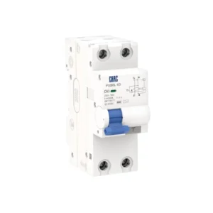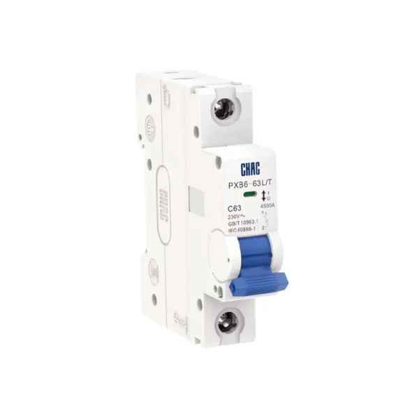
PXB6-63 L/T Miniature Circuit Breaker
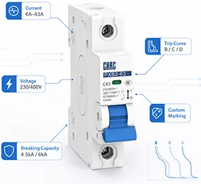
The PXB6-63 L/T miniature circuit breaker provides overload and short-circuit protection within the published 6A–63A range. Its verified product data lists 4.5kA Icu = Ics, 1P / 2P / 3P / 4P and B / C / D. Final selection must match the conductor, load, prospective fault current, installation system and applicable local rules.
Product Overview
PXB6-63 L/T is a 4.5kA Icu = Ics miniature circuit breaker covering 6A–63A. It is available with 1P / 2P / 3P / 4P and B / C / D trip options as stated in the product data.
The model data references IEC 60898-1; GB/T 10963.1 and lists CCC certification. Standards, certification scope and technical documents must be confirmed for the ordered configuration and destination market.
Key Features
Typical Applications
It is intended for AC distribution circuits where the selected current rating, curve, pole arrangement and breaking capacity match the conductor and system study. Typical project contexts include residential, commercial and light-industrial final distribution; suitability depends on the actual circuit rather than the application label alone.
Applications and Selection Guide
Use the product-specific values below as a shortlist, then validate the complete circuit design. Product ratings do not replace a fault-current study, conductor calculation, coordination review or applicable installation rules.
| Selection point | PXB6-63 L/T option | What the project must confirm |
|---|---|---|
| Rated current | 6A–63A | Coordinate with design current, conductor ampacity, ambient temperature and grouping |
| Trip curve | B / C / D | Choose for load inrush and required fault-clearing performance, not by current alone |
| Breaking capacity | 4.5kA Icu = Ics | Confirm against the prospective short-circuit current at the installation point |
| Pole arrangement | 1P / 2P / 3P / 4P | Match supply system and local switching or isolation rules |
| Installation interface | 45mm terminal-centre reference | Check enclosure, rail/base, terminal and conductor compatibility |
Breaking Capacity
4.5kA Icu = Ics is the published product value. Confirm the prospective short-circuit current at the installation point.
Trip and Load Behaviour
B / C / D is the available trip/protection option. Match it to load inrush and required disconnection performance.
Pole Configuration
Available arrangement: 1P / 2P / 3P / 4P. Confirm which conductors must be switched and protected under local rules.
MCB or RCBO
An MCB does not replace residual-current protection where an RCD or RCBO is required.
Ordering Guide
- Specify the exact model: PXB6-63 L/T.
- State the required current rating within 6A–63A.
- Confirm pole arrangement: 1P / 2P / 3P / 4P.
- Confirm trip or protection option: B / C / D.
- Provide system voltage, expected fault level, destination market, quantity and any document requirements.
Installation and Coordination Checks
- Verify conductor material and cross-section against the circuit calculation and the published terminal range.
- Confirm the prospective short-circuit current does not exceed the applicable breaking rating.
- Check upstream/downstream coordination, enclosure temperature, grouping, altitude and required clearances.
- Installation, isolation, testing and maintenance must be carried out by qualified personnel under applicable rules.
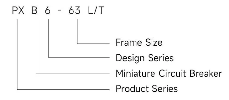
Type designation
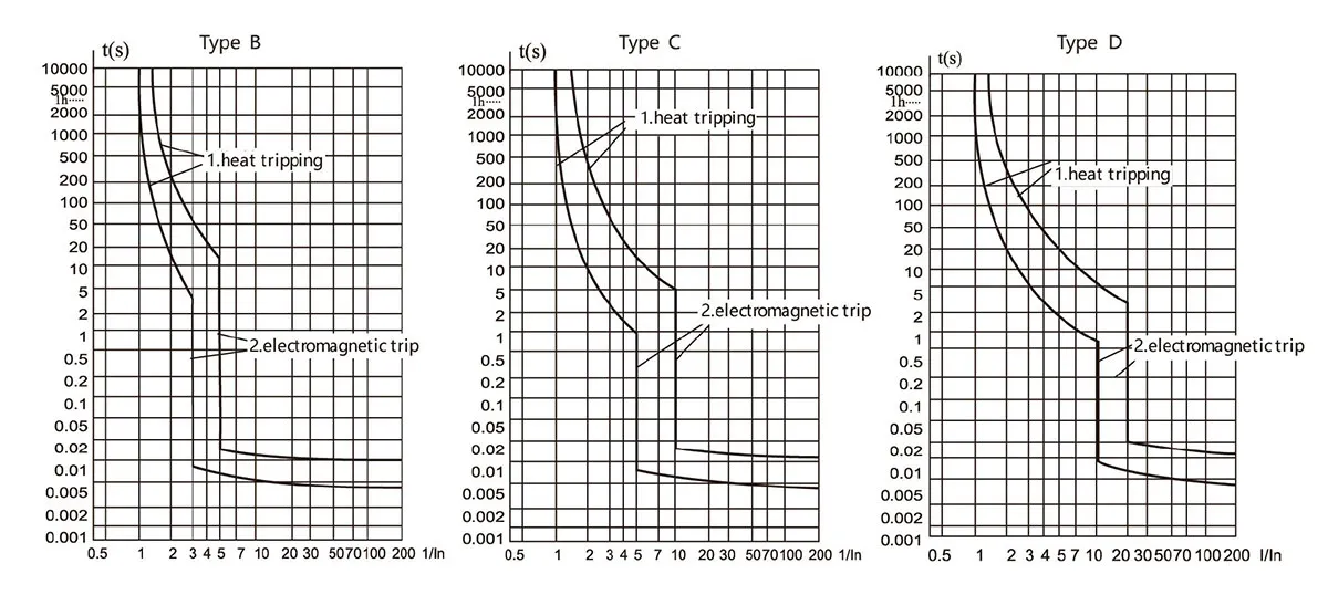
Tripping curves
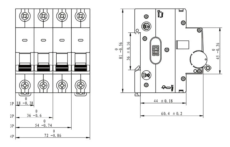
Dimensions(mm)
Technical Specifications
| Parameter | |
| Rated Insulation Voltage (Ui) | 500V |
| Rated Impulse Withstand Voltage (Uimp) | 4000V |
| Rated Current (In) | 6, 10, 16, 20, 25, 32, 40, 50, 63 |
| Rated Frequency | 50Hz / 60Hz |
| Number of Poles | 1P, 2P, 3P, 4P |
| Rated Short-Circuit Breaking Capacity (Icu = Ics) | 4500A |
| Mechanical Life | ≥10000 |
| Electrical Life | ≥4000 |
| Tripping Curves | B, C, D |
| Terminal Center Distance | 45mm |
| Protection Class | IP20 |
| Standard | IEC60898-1, GB/T10963.1 |
| Certification | CCC |
Tripping Characteristics (Reference Temperature: 30°C)
| Item | Tripping Curve | Test Current (A) | Initial Status | Time limit for tripping or non-tripping | Expected result | Remarks |
| a | B, C, D | 1.13In | Cold | t ≤ 1h | Non-tripping | Current smoothly rises to specified value within 5s |
| b | B, C, D | 1.45In | Following item a test | t < 1h | Tripping | |
| c | B, C, D | 2.55In | Cold | 1s < t < 60s (In ≤ 32A) 1s < t < 120s (In > 32A) |
Tripping | |
| d | B | 3In | Cold | t ≤ 0.1s | Non-tripping | Switch on the power supply by closing the auxiliary switch |
| C | 5In | |||||
| D | 10In | |||||
| e | B | 5In | Cold | t < 0.1s | Tripping | Switch on the power supply by closing the auxiliary switch |
| C | 10In | |||||
| D | 20In |
Note: The term “cold” means that the test is carried out at a reference calibration temperature without load before the test.
Conductor requirements and cross section
| Copper cross-section(mm2) | Rated current In(A) |
| 1 | In≤6 |
| 1.5 | 6<In≤13 |
| 2.5 | 13<In≤20 |
| 4 | 20<In≤25 |
| 6 | 25<In≤32 |
| 10 | 32<In≤50 |
| 16 | 50<In≤63 |
Why Choose CHAC
With 30+ years of manufacturing experience, 1100+ employees, 100M+ poles
annual capacity and 90% automated production, CHAC provides stable production capacity and strict
quality control for global OEM/ODM customers. Our in-house manufacturing system supports long-term
cooperation for electrical brands, importers and distributors.

30+
YEARS EXPERIENCE
Specialized in low-voltage electrical manufacturing

1100+
EMPLOYEES
Professional team ensures stable quality and delivery

100M+
POLES ANNUAL CAPACITY
Large-scale production capacity to meet global demand

90%
AUTOMATED PRODUCTION
Advanced automation for high efficiency and consistency

Automated Assembly Line

Testing Laboratory
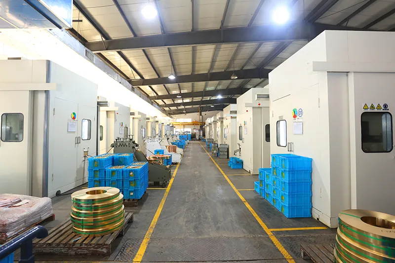
Injection & Stamping

Quality Inspection



Strict quality control system ensures every product meets global standards.
What Can We Customize?
For PXB6-63 L/T projects, CHAC can review private-label marking, packaging, appearance, available electrical configurations and technical-document requirements. Requests outside the published range are subject to engineering evaluation, testing, MOQ and project feasibility.

Logo & Branding
Private-label marking and nameplate options are subject to artwork review and sample approval.


Packaging
Customization
Cartons, labels and manuals can be prepared for the approved order specification and destination market.

Electrical
Customization
Select from the published 6A–63A, 1P / 2P / 3P / 4P and B / C / D options; non-standard requests require technical evaluation.

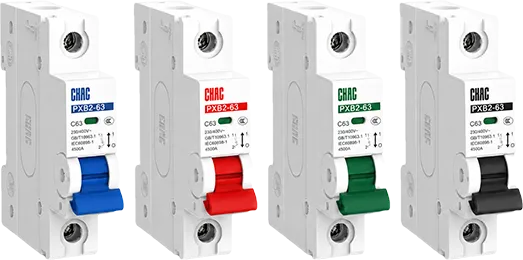
Product
Appearance
Appearance options can be reviewed subject to tooling, MOQ, marking requirements and technical feasibility.

Certification
Support
Datasheets, drawings and verified certificate information are supplied for the applicable approved configuration.


Engineering
Development
Project support may include drawing review, sample evaluation, testing and production planning, subject to technical approval.

Download
PXB6 Series Miniature Circuit Breaker
Complete product overview for low-voltage electrical components and product selection reference.
Need Technical Documents?
Contact us for datasheets, certificates, drawings, selection guidance or OEM/ODM project support.
PXB6-63 L/T Product FAQ
What is an MCB trip curve?
It describes the time-current response and instantaneous magnetic-trip behavior. PXB6-63 L/T offers B, C and D curves for different inrush and fault-clearing requirements.
Which curve is best for the PXB6-63 L/T?
No curve is universally best. B generally suits lower inrush, C moderate inrush and D higher inrush, provided the available fault current can still achieve the required disconnection.
When should the PXB6-63 L/T use a C curve?
C curve is commonly evaluated for circuits with moderate starting current. Confirm the real load profile, conductor protection and fault-loop conditions before selection.
Will a 20A breaker trip exactly at 20A?
Not instantaneously. Thermal trip time depends on how far and how long current exceeds the rating, along with reference temperature and product characteristics.
Does the 80% rule apply to every circuit breaker?
No. The phrase is associated with particular market rules and applications; it should not be treated as a universal IEC requirement. Follow the governing installation standard and circuit calculation.
What is the 125% rule in electrical design?
It commonly describes market-specific treatment of continuous loads or conductor sizing. Apply only the rules that govern the project and do not use a fixed percentage as a substitute for verified PXB6-63 L/T data.
Confirm the Right PXB6-63 L/T Configuration
Send your current rating, pole arrangement, trip option, system voltage, prospective fault level, destination market and quantity. CHAC will review the request against the published product range.