A feeder that trips when several drives start presents a selection question, not an automatic diagnosis of a defective breaker. Increasing the earth-leakage pickup current or delay may suppress an interruption without establishing that the circuit remains adequately protected. The designer must distinguish normal load leakage from a wiring or insulation fault, check the residual-current waveforms that the loads can produce, and decide whether the device serves feeder coordination or a required personal-protection function. This guide explains when an integrated molded-case breaker is useful, which CQM6L details require exact-model documentation, and why settings, neutral routing, and commissioning evidence must be assessed together.
The short answer is that a leakage-integrated molded-case автоматический выключатель is appropriate when a project needs overload, short-circuit, and earth-leakage functions at the same location, provided the exact device meets the circuit’s requirements. Schneider Electric’s Electrical Installation Guide identifies industrial breakers with integrated RCD functions under IEC 60947-2 and Annex B. That device category does not establish a CQM6L variant’s waveform response, personal-protection suitability, or approval in a particular market. Select from the circuit study, confirm the ordered configuration, and commission the protection functions according to the manufacturer’s instructions and local installation rules.
When Does a Leakage-Integrated MCCB Make Sense?
A current-operated earth leakage автоматический выключатель responds to residual-current imbalance, while an MCCB addresses overload and short-circuit protection within its declared characteristics. Combining those functions can reduce panel space, wiring interfaces, and procurement line items. It does not remove the need to coordinate conductors, protective devices, earthing arrangements, and isolation requirements as a complete system. Schneider Electric’s Form factors of RCDs distinguishes integrated industrial breakers from domestic residual-current devices and relays with separate toroidal current transformers.
The integrated approach is most useful when the protected feeder genuinely needs both functions at the same location, the prospective short-circuit current is within the declared breaking duty of the exact device, and the leakage settings can coordinate with upstream and downstream protection. A separate MCCB plus residual-current relay or downstream protective devices may be more suitable when the project needs independent replacement, broader setting flexibility, remote sensing, or more selective zone coordination.
Total cost should include more than the purchase price. One integrated device may reduce installation labor and panel footprint, but a nuisance trip can interrupt the whole feeder, and replacement may remove both protection functions from service. An illustrative comparison can use: installed device and wiring cost + commissioning time + expected interruption cost + inspection and replacement effort. Use project data for every input rather than assuming that the lowest component count creates the lowest lifecycle cost.
What Does the CQM6L Protect, and Which Ratings Need Checking?
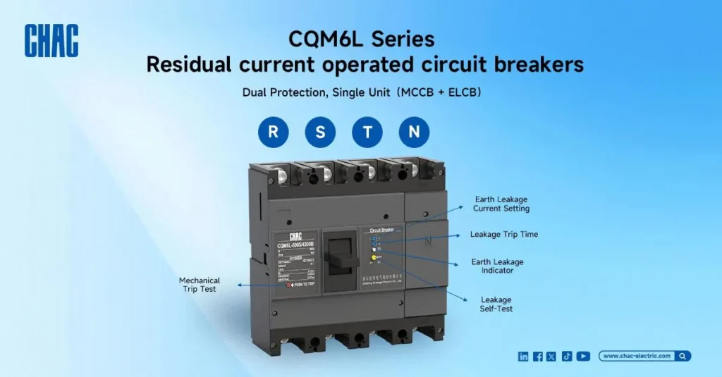
The CQM6L is presented as a leakage-integrated MCCB combining overload, short-circuit, and earth-leakage functions. Its family name is not a complete specification. Before selecting a variant, obtain the applicable product sheet and ordering schedule for rated operational voltage, frame, rated current, poles, leakage pickup, delay, and breaking-duty values. Only use values documented for the exact configuration; a catalog maximum does not establish the rating of every variant.
| Protection function | What it addresses | Critical selection question | Свидетельства для сохранения |
|---|---|---|---|
| Overload | Sustained overcurrent that can overheat conductors or equipment | Does the ordered rated current and trip characteristic coordinate with load, conductor ampacity, ambient temperature, grouping, and motor-starting duty? | Load schedule, cable calculation, trip curve, and exact model data |
| Short circuit | High fault current requiring interruption | Are the declared breaking capacities adequate for the calculated prospective fault duty at the system voltage, with any required service-continuity criterion checked separately? | Short-circuit study, device declaration, and upstream/downstream coordination data |
| Earth leakage | Residual-current imbalance through the sensing arrangement | Are sensitivity, delay, waveform behavior, neutral routing, and earthing arrangement suitable for the circuit and local rules? | Wiring diagram, setting record, and instrumented trip-test results |
| Isolation, where declared | Separation for work under the applicable procedure | Is suitability for isolation explicitly declared for the exact device and installation? | Manufacturer declaration, installation instructions, and site isolation procedure |
Frame size, rated current, and overload pickup are different quantities. Where an adjustable trip unit is fitted, its setting must protect the conductors under the actual installation conditions; the frame marking alone cannot do that. Schneider Electric’s Fundamental characteristics of a circuit-breaker also distinguishes ultimate short-circuit breaking capacity Icu from service short-circuit breaking capacity Ics. Compare declarations at the applicable operational voltage and standard test context, not merely the largest kA number.
How Should CQM6L Settings, Wiring, and Fault Duty Be Checked Before Energizing?
Residual current protection works by evaluating the vector sum of currents through the intended sensing path. The designer must therefore verify whether the neutral is present, whether it passes through the sensing arrangement, how the ordered pole configuration switches or protects it, and whether any parallel or downstream neutral-earth path could invalidate the intended measurement. Do not infer terminal positions, supply direction, neutral treatment, or accessory compatibility from another frame size.
Why Does the Circuit Diagram Matter More Than the Faceplate?
First establish system voltage and earthing arrangement, design current, conductor capacity, load type, expected leakage, prospective short-circuit current, and required disconnection behavior. Next select a frame and rated current, then verify the exact breaking-duty values at the declared voltage. Finally, coordinate the leakage pickup and time delay with upstream and downstream devices so that a downstream fault does not unnecessarily disconnect a larger part of the installation.
For a feeder supplying both three-phase and line-to-neutral loads, retain a drawing showing the complete sensing boundary, not just the number of switched poles. The supplier should confirm the supported neutral arrangement for the ordered variant, including any neutral conductor that must pass through a sensor. A neutral shared with a circuit outside that boundary can disturb the intended current balance. A four-pole description alone does not prove which conductors are protected, how the neutral is switched, or whether the assembly suits that mixed-load feeder.
Why Does a Longer Delay Not Prove Selectivity?
A higher delay may reduce unwanted upstream operation, but time separation alone does not prove selectivity. Pickup tolerances, device curves, fault magnitude, waveform response, and the settings of devices on both sides must be reviewed using manufacturer coordination information or a documented engineering study. Similarly, raising the leakage pickup current or extending the delay to stop nuisance trips can conceal a wiring or insulation problem rather than solve it.
Does Selective Feeder Protection Also Provide Personal Protection?
Not automatically. Feeder selectivity concerns which device disconnects and how much of the installation remains in service. Personal-protection requirements concern the protective measures and disconnection behavior required for the circuit and its users. An upstream time-delayed device chosen to coordinate with downstream protection must not be assumed to replace a required final-circuit protective device. Record those two duties separately in the protection schedule and verify each against the applicable installation rules.
Waveform compatibility is a separate check again. Schneider Electric’s Types of RCDs distinguishes Type A detection of pulsating DC residual current from Type B detection that also includes smooth DC and specified multifrequency residual currents. Adjustable pickup and delay do not establish either classification. For drives or other electronic loads, obtain the equipment manufacturer’s protection requirements and the exact CQM6L waveform declaration before approving the combination. Do not infer Type A, F, or B capability from the family name or from the characteristics of another manufacturer’s breaker.
| Checkpoint | Selection evidence | Commissioning verification | Do not accept as a substitute |
|---|---|---|---|
| Rated current and conductors | Load and cable calculation for actual installation conditions | Installed conductor, terminal, torque, and setting inspection | Frame size alone |
| Ответственность за нарушение правил | Prospective short-circuit current and exact Icu/Ics data at system voltage | Installation matches the studied point and upstream arrangement | A family maximum breaking capacity |
| Leakage pickup and delay | Protection study, load leakage assessment, and applicable rules | Recorded instrument test at the configured setting where required | Pressing the test button only |
| Neutral and sensing path | Exact model wiring diagram and earthing arrangement | Visual and electrical verification of all intended live conductors | Assuming every pole variant is wired alike |
| Upstream/downstream discrimination | Time-current data and documented coordination review | Settings sealed or recorded against the approved schedule | Delay difference without curve evidence |
| Residual-current waveform | Load requirements and exact device waveform declaration | Applicable manufacturer-specified checks with suitable instruments | Adjustability or an integrated-device name |
What Should Be Tested Before Commissioning, and What Does IEC 60947-2 Cover?
A test button is a functional check whose scope depends on the device design; it does not by itself verify conductor continuity, insulation condition, fault-loop performance, prospective fault current, or the actual trip time/current at the installed settings. Commissioning should follow the applicable local verification rules and the manufacturer’s instructions, with testing performed by qualified personnel using suitable instruments. Typical evidence may include visual inspection, protective-conductor continuity, insulation-resistance results, polarity where applicable, fault-loop or prospective-fault-current verification, and an instrumented residual-current operating test.
IEC 60947-2 is a product standard for industrial circuit-breakers. The Electrical Installation Guide identifies Annex B for breakers incorporating residual-current protection and Annex M for modular residual-current devices with separate sensing arrangements. That distinction helps identify the documentation to request; it does not establish conformity of an individual CQM6L variant. Product conformity and verification of the installed circuit are separate checks.
Procurement teams should request the exact declaration, report, certificate where relevant, and model traceability needed for the destination market and intended use. Marketing language, a catalog reference, or a test method name should never be converted into an unsupported certification claim. IEC-based product documentation also does not by itself establish approval for a US panel or satisfy its equipment-specific listing requirements.
What Should Buyers Confirm Before Ordering a CQM6L?
CHAC publishes the CQM6L family as an integrated option, but the buying decision should be tied to the exact bill of materials and evidence package. Before approving a sample or production order, use this checklist:
- Define the circuit: record voltage, frequency, phase arrangement, earthing system, load profile, design current, conductor conditions, and destination-market rules.
- Confirm the exact variant: match frame, rated current, poles, neutral treatment, operating mechanism, terminals, accessories, leakage code, and delay code to the model schedule.
- Verify fault duty: compare the calculated prospective short-circuit current with the exact device’s breaking-capacity declarations at the system voltage; do not use the family maximum as a blanket rating.
- Review coordination: compare upstream and downstream time-current and leakage characteristics, including tolerances, waveform compatibility, and continuity requirements.
- Approve the wiring plan: use the exact instruction sheet to verify supply direction, conductor routing, sensing path, neutral treatment, clearances, terminals, and accessory connections.
- Define acceptance tests: agree on functional checks, instrumented residual-current tests, circuit-verification results, setting records, and the documents that must accompany each batch.
For a broader comparison of device families, see the MCCB versus MCB selection guide and the range of molded-case circuit breakers. When the integrated architecture is justified, review the CQM6L leakage-integrated MCCB and request confirmation against your one-line diagram and protection schedule.
What Else Do Buyers Ask About CQM6L Selection?
How to choose ELCB rating?
Choose the device from the system voltage, design current, conductor capacity, prospective fault current, earthing arrangement, required leakage sensitivity and delay, and local installation rules. Then verify the exact ordered variant’s breaking duty, poles, neutral treatment, and trip characteristics; an ampere rating alone is not a complete selection.
How to check residual current circuit breaker?
Use the manufacturer’s test control for the specified routine functional check, then perform the instrumented tests required by the applicable installation standard and commissioning plan. A successful button test does not replace wiring inspection, measured trip performance, insulation testing, or fault-loop verification.
What is a residual current breaker?
It is a protective device that detects an imbalance between currents flowing in the intended live-conductor sensing path and disconnects when its operating criteria are met. Its function and suitability depend on device type, sensitivity, delay, waveform response, wiring, and the installation rules for the application.
What is a molded case breaker?
A molded-case circuit breaker is a circuit-breaker housed in a molded insulating case, commonly selected for feeder or equipment circuits requiring declared current and short-circuit performance. Available trip units, accessories, breaking capacities, and adjustment ranges vary, so the exact model must be checked rather than relying on the family name.
Does an adjustable leakage setting make one breaker suitable for every feeder?
No. Adjustment provides options within the device’s declared range, but the correct setting still depends on expected leakage, disconnection requirements, coordination, load behavior, and local rules. An upstream selective setting does not establish that required downstream personal protection is provided.
What if the supplier cannot document the CQM6L’s residual-current type?
Do not approve it for a load requiring a particular waveform response on the assumption that an integrated breaker has that capability. Request a declaration and supporting documentation tied to the exact ordered variant, then compare them with the load manufacturer’s instructions. If that evidence remains unavailable, the protection design needs a documented alternative rather than an assumed Type A or Type B classification.
Which Sources Explain These Selection Checks?
The following Schneider Electric Electrical Installation Guide pages were checked on October 7, 2026; each was last edited on August 5, 2026. They explain general selection principles, not CHAC-specific ratings or certification.
- Form factors of RCDs: integrated industrial protection, domestic devices, and separate-sensor arrangements.
- Types of RCDs: waveform-dependent residual-current classifications.
- Fundamental characteristics of a circuit-breaker: voltage, current, frame, settings, isolation, and breaking-capacity distinctions.
An adjustable device becomes a protection solution only when the exact configuration is supported by the circuit study, wiring plan, coordination review, and recorded tests. Establish the feeder’s protection duties first, including any required downstream personal protection, then confirm current and fault duty, residual-current waveform response, and the neutral sensing boundary. Do not trade away an installation requirement simply to eliminate an unwanted trip. The remaining approval step is documentary: the ordered model must match the evidence used in the design. To review a CQM6L configuration for an OEM panel or distribution project, связаться с CHAC Electric with the one-line diagram, load information, fault level, required settings, destination market, and documentation list.