
Two installations described as “240V” can need different breaker arrangements. A North American 120/240V split-phase circuit supplies a line-to-line load from two live conductors; a line-to-neutral single-phase supply presents a different neutral and isolation question. Dividing appliance watts by 240 does not resolve either case, nor does it establish a conductor size, panel-compatible breaker or sufficient fault rating. Those omissions can create redesign work even when the calculated running current is correct. This guide separates supply topology, load calculation, cable protection and installation verification so an engineer or buyer can specify the device without turning a voltage label into a universal wiring recipe.
The short answer is to select a كسارة الحائط 240 فولت from the actual supply arrangement, equipment requirements, load current, conductor ampacity and available fault current. For a purely resistive single-phase 4.8kW load at 240V, the illustrative operating current is 20A. That does not by itself establish a 20A breaker or a particular wire gauge. Under the IEC-based selection method, IB ≤ In ≤ Iz links design current, protective-device rating and corrected conductor capacity. Apply the destination’s adopted code and equipment instructions, then confirm poles, common operation, fault interruption and panel compatibility.
Does a 240V circuit always need the same pole arrangement?
No. Identify the supply conductors before selecting the device. In a 120/240V split-phase system, a line-to-line load uses two ungrounded conductors. The protective and disconnecting arrangement must meet the circuit’s common-operation and applicable common-trip requirements. A neutral, when the equipment needs one, serves a different purpose from the protective-earth conductor.
A line-to-neutral supply cannot simply be copied from that drawing. Local rules determine neutral switching and isolation, and a 1P+N device is not automatically equivalent to a breaker with two protected poles. Read the circuit diagram and the manufacturer’s pole description. Never treat protective earth as an interchangeable return conductor.
| Supply or load arrangement | Main distinction | What to confirm |
|---|---|---|
| 120/240V split-phase, line-to-line load | Two ungrounded conductors supply the load | Required linked disconnection, trip arrangement and panel-compatible device |
| Single-phase line-to-neutral supply described as 240V | Line and neutral have different circuit roles | Neutral switching, protected poles and the adopted isolation rules |
| Equipment needing both line-to-line and line-to-neutral loads | The equipment may need a neutral as well as protective earth | Nameplate, approved wiring diagram and conductor functions |
| DC circuit with a nominal 240V bus | DC interruption is a separate duty | Maximum DC voltage, polarity and specifically declared DC suitability |
This is a specification comparison, not a terminal-by-terminal installation diagram. US workplace installations covered by OSHA 1910.303 [3] must use listed or labeled equipment according to its included instructions. Equivalent-looking devices are not interchangeable merely because they fit the panel opening.
How do watts convert into current at 240V?
For a single-phase resistive load, I = P ÷ V. Thus 4,800W ÷ 240V = 20A. The corresponding apparent power is 4.8kVA; real power is 4.8kW only under the unity-power-factor assumption. For a non-unity-power-factor load with a known electrical input power, use I = P ÷ (V × power factor), subject to the equipment’s actual operating characteristics.
Motor output power is not the same as electrical input power. Motors, compressors, electronic power supplies and heating equipment with controls can require application-specific sizing rules or nameplate data. Where a manufacturer states minimum circuit ampacity or maximum overcurrent protection, use those instructions with the governing code instead of substituting a general calculator.
| Assumed load at 240V | Calculation | Result and limitation |
|---|---|---|
| 2.4kW resistive electrical input | 2,400 ÷ 240 | 10A running current; verify duty and conductor protection |
| 4.8kW resistive electrical input | 4,800 ÷ 240 | 20A running current; not automatic permission for a 20A breaker |
| 4.8kW electrical input, power factor 0.8 | 4,800 ÷ (240 × 0.8) | 25A under the stated assumptions; starting current is a separate check |
Continuous-load allowances depend on the applicable rules and equipment rating. Do not apply a universal 80% or 125% shortcut across markets and equipment types. Establish which rule applies, then check the conductor and protective device together. Lower running current does not remove an inrush or fault-disconnection requirement.
What determines wire size and breaker amperage?
Conductor ampacity is the permissible current under the actual installation conditions. Material, insulation, installation method, ambient temperature and grouping can change it. The route length also matters for voltage drop and the fault conditions at the end of the circuit. A breaker rating alone cannot define a universally correct AWG or square-millimetre size.
شركة شنايدر إلكتريك IEC-based protective-scheme guidance [1] gives IB ≤ In ≤ Iz: design current must fit within the protective rating, which must fit within the conductor’s corrected capacity. The same guidance addresses the conventional operating-current condition and short-circuit protection. These relationships are useful for an IEC-based design review; they do not replace appliance-specific exceptions or another jurisdiction’s adopted code.
Record the terminal’s permitted conductor material, size range, temperature rating and preparation method separately from the cable calculation. A cable that is thermally adequate may still be unsuitable for a particular terminal. Reducing the conductor to make it fit, or increasing breaker amperage to stop tripping, bypasses the required review.

How do trip curve and fault rating affect the choice?
قوة الكسر must cover the prospective fault current at the installation point and the applicable voltage. For example, a hypothetical 6kA-rated device is insufficient as a standalone choice where the available fault current is 8kA. An approved coordinated combination is a separate engineering decision; the presence of an upstream breaker alone is not evidence of adequate backup protection.
The trip characteristic answers a different question. As described in the Electrical Installation Guide [2], instantaneous thresholds differ by curve and product standard. A curve that tolerates a higher starting current may also require more fault current for rapid operation. Resolve a nuisance trip by checking the load, inrush and fault path, not by automatically selecting a slower characteristic.
Panel compatibility adds a third check: mounting, terminals, approved busbar interface and the equipment’s permitted devices must all agree. A mechanically fitting breaker can still have an unsuitable electrical interface. Keep standard, listing and assembly requirements tied to the destination market; an IEC standard declaration does not establish approval for a North American load center.
What should an engineer or buyer specify before installation?
- State supply voltage, frequency, earthing arrangement and which conductors feed the equipment.
- Record the nameplate requirements, design current, duty and starting behavior.
- Determine corrected conductor capacity, voltage drop and termination requirements.
- Choose the pole/trip arrangement, fault rating and approved panel interface.
- Retain the approved diagram, exact part number and commissioning requirements.
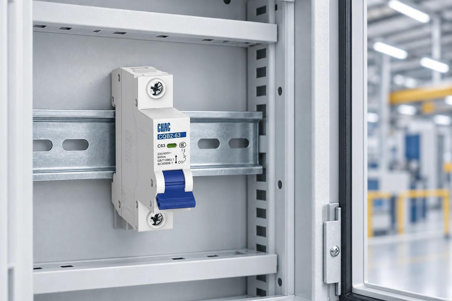
شركة CHAC CQB2-63 product record provides a useful example of the fields to inspect: 230/400V AC, 6–63A options, B/C/D curves, multiple pole arrangements and 6kA breaking capacity. Those published values describe that family; they do not establish that every variant is acceptable for a system described as 240V. Confirm the permitted application and destination-market documentation. The 40A double-pole MCB guide applies the same load-and-cable review to a different current rating.
Include installation labor, compatible accessories, documentation and future replacement availability in the cost comparison. A cheaper device can create additional cost when it needs a new enclosure layout, different terminals or renewed approval. These are cost drivers to quote and evaluate, not a claimed saving percentage.
Installation and verification belong to qualified personnel using the approved isolation procedure and the applicable testing requirements. Confirm connections, conductor identification, torque and the required protective functions before service. Insulation testing must follow equipment instructions and account for connected electronics. Do not improvise a short circuit to demonstrate breaker operation.
الأسئلة الشائعة
كم أمبير يساوي 20 أمبير عند 240 فولت؟
The current is 20A. At 240V, apparent power is 4.8kVA; real power is 4.8kW for a unity-power-factor load. The calculation does not settle continuous-duty allowances or cable selection.
ما هو مقياس السلك المستخدم في مقبس 240 فولت؟
There is no wire size determined by 240V alone. Use load current, corrected ampacity, conductor material, route, voltage drop and terminal requirements under the adopted code.
هل أحتاج إلى مقبس مفاتيح مزدوج للجهد 240 فولت؟
A line-to-line split-phase load uses two ungrounded conductors and needs the protection and disconnection arrangement required for that circuit. A line-to-neutral system presents a different neutral-switching question. Confirm the supply diagram and local rules.
كيف ينبغي اختبار مقبس 240 فولت؟
Use the manufacturer’s instructions and the installation’s required verification procedure. Qualified personnel should determine the appropriate inspection, continuity, insulation, functional and protective-device tests. A deliberate field short circuit is not a substitute for controlled verification.
Can a 230V MCB automatically be used on a nominal 240V supply?
No automatic conclusion follows from the numbers being close. Confirm the device’s declared operating-voltage application, supply tolerance and required approval. A higher insulation rating does not replace that confirmation.
المراجع
Sources checked 20 October 2026. The two Electrical Installation Guide pages show revisions dated 5 August 2026. Numerical load examples above are explicitly calculated assumptions, not installation recommendations.
- Schneider Electric, Electrical Installation Guide: Practical values for a protective scheme.
- Schneider Electric, Electrical Installation Guide: Fundamental characteristics of a circuit-breaker.
- US OSHA, 29 CFR 1910.303: equipment approval, use, interrupting rating and connections.
الخاتمة
A 240V description establishes neither a complete circuit nor a finished breaker selection. First identify the supply and equipment requirements, then calculate design current and conductor capacity before checking poles, trip behavior, available fault current and assembly compatibility. Keep a calculated running current separate from the final protective-device rating, especially where continuous duty, starting current or appliance-specific rules apply. The installation record should explain why the chosen device fits those conditions so a later replacement can be reviewed against the same evidence. CHAC’s miniature circuit-breaker range provides product families for that comparison, while exact voltage suitability and market acceptance still require confirmation. For a model review, share the load schedule, supply arrangement and required documents with CHAC.