A nominal coil voltage is not a complete interface specification. A contactor can operate on a bench yet fail to pull in when several panel loads start together, or release too slowly after its command disappears. OEM engineers need to match the coil supply, output device and operating sequence, then verify the assembled circuit at the coil terminals.
The short answer is to specify AC or DC, rated voltage and any required frequency, plus model-specific pickup, holding and release conditions. Separate the starting burden from the holding burden. Check supply capacity, cable drop, output compatibility and approved suppression together; none can be inferred from the power-contact rating. An IEC-oriented design should use the selected model’s documentation, not voltage percentages copied from another product family.
Which coil supply must the interface support?
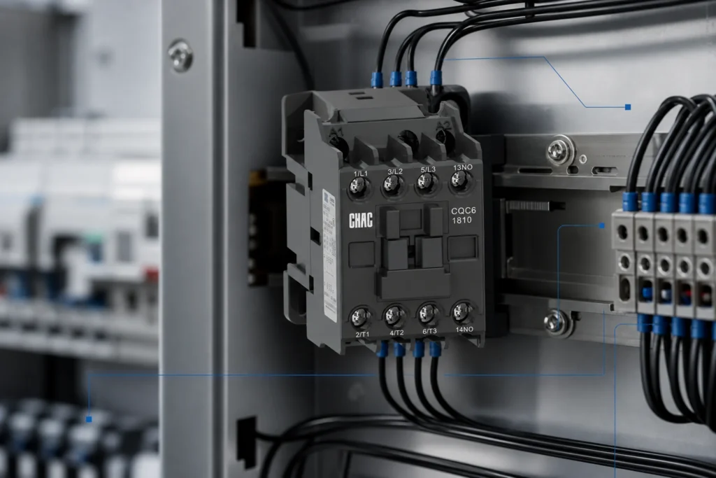
Record the full contactor coil code, not just the contactor frame size. Identify AC or DC and, for an AC coil, the documented frequency. A matching voltage number does not establish interchangeability between AC, DC, 50 Hz and 60 Hz variants.
If a manufacturer offers an electronic or wide-range coil, obtain that variant’s input and release data. Do not assume a conventional coil has electronic control, polarity independence or voltage-dip ride-through.
How do pickup, holding and dropout differ?
Pickup closes the magnetic assembly from rest; holding keeps it closed; dropout describes release as excitation falls. A coil that remains closed at a given terminal voltage may not start reliably at that voltage. The relevant limits, temperature conditions and timing must come from the exact model.
| Condition | Design question | Evidence needed |
|---|---|---|
| Pickup | Can every commanded contactor close? | Pickup limits and starting burden |
| Holding | Can the supply sustain the energized group? | Holding consumption and permitted conditions |
| Dropout | Will the mechanism release when required? | Release limits and timing with suppression |
Will the supply survive simultaneous starts?
Size the control transformer or DC supply for the documented starting and continuous burdens of the actual combination. Include other loads on that supply. A steady-state total alone can miss the interval when several coils are pulling in.
Measure control voltage at the coil terminals during the worst intended start sequence, not only at the supply output. Include the outgoing and return paths, terminal connections and switching-device drop. Cable resistance, shared returns and supply response can change the result.
Record terminal voltage, command and auxiliary-contact response during simultaneous starts, repeated starts and specified supply dips. Define acceptance criteria from model documentation and the machine’s operating requirements; a successful single start is insufficient evidence.
Can the PLC output drive and release the coil?
Compare the coil burden with the output’s load-type rating, making or switching capacity, continuous rating and channel-group limits. For transistor outputs, also check supply type, polarity, leakage and voltage drop. Use an appropriately rated interposing interface when direct drive is not supported.
Specify only manufacturer-approved suppression for the selected coil and output. Suppression can affect release timing, so verify the complete combination rather than adding a generic diode or RC network by habit. Assess residual excitation with the command off.
Der control-wiring guide for panel builders provides related drawing context; it does not replace coil or PLC output data.
What should happen after a dip or trip?
Define whether supply loss removes the run command, whether recovery requires a deliberate restart, and how feedback discrepancies are handled. Do not treat coil ride-through, command retention and permission to restart as the same function. Validate the sequence against the machine’s risk assessment.
An overload reset is another separate event. Schneider Electric’s LRD reset FAQ explains that reset time depends on trip type, hot or cold state and ambient conditions; the bimetal sensors must cool before reset. That source does not establish CHAC relay timing or authorize automatic motor restart.
What evidence should accompany the selected model?
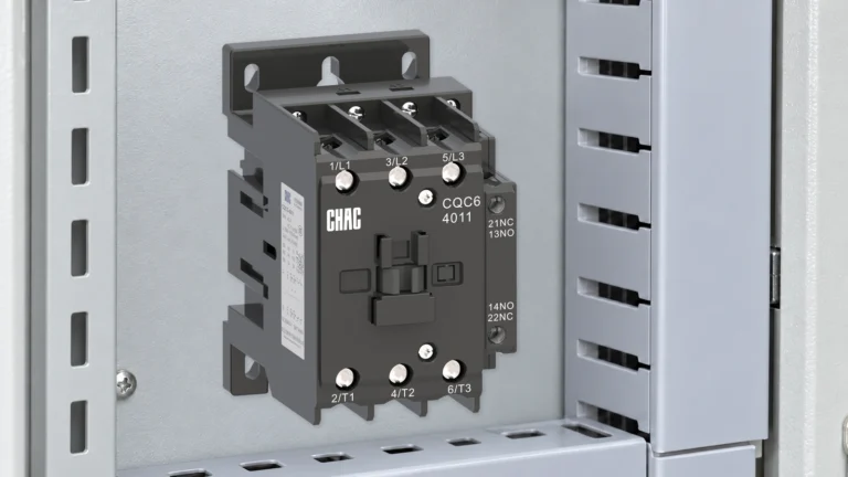
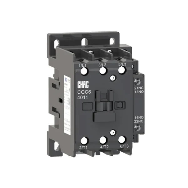
CHAC’s CQC6 AC contactor page identifies a remote-switching and motor-control product route. Approval still requires the exact variant’s coil and interface documentation. The contactor coil category route helps locate the family, not establish a universal coil rating.
| Approval record | What it must resolve |
|---|---|
| Variant datasheet | Coil code, supply, frequency, burdens and operating limits |
| Interface documents | Output rating and approved suppression compatibility |
| Panel test record | Terminal voltage, feedback and release under specified sequences |
CQC6 Series Industrial AC Contactor: confirm the selected variant before approving the coil interface.
Does noise always mean low voltage?
No. Schneider Electric’s Type S noise FAQ lists inadequate voltage and incorrect coils alongside broken shading coils, misalignment, dirt, binding and mounting issues. It also distinguishes characteristic AC hum from abnormal noise. Its Type S NEMA size 5 scope is not a specification for every IEC contactor.
Check terminal voltage and coil identity, then inspect mounting and mechanical condition under the manufacturer’s instructions. Isolate equipment before inspection; do not adjust energized mechanisms or increase voltage to conceal noise.
Häufig gestellte Fragen
Can an AC contactor use a DC coil?
Only if the manufacturer documents the corresponding variant or approved conversion. The main contacts do not determine the coil supply.
Is matching nominal voltage enough?
No. Supply type, frequency, burden and operating limits must also match.
Why does a coil hold but fail to pick up?
Pickup and holding are different conditions. Check terminal voltage during pickup against the selected model’s requirements.
Can a PLC drive any small coil directly?
No. Check the output’s applicable load rating and the coil’s starting burden, not its physical size.
Can suppression delay release?
It can affect release timing. Validate the manufacturer-approved coil, suppressor and output combination.
Should power recovery restart the motor?
Not by default. Restart permission depends on the machine’s assessed operating and safety requirements.
Verweise
- Schneider Electric: Type S contactor noise causes, updated May 12, 2026; product-specific NEMA scope.
- Schneider Electric: LRD bimetal overload reset timing, updated August 11, 2026.
- CHAC CQC6 product page, linked above; product-route information checked October 10, 2026.
A coil interface is approved as a circuit, not as a voltage label. Confirm the variant, supply and output first, then verify pickup, sustained operation and release in the assembled panel. For missing variant data, contact CHAC with the coil code and control schematic.
Für eine ähnliche Auswahlhinweise siehe How Should OEM Panel Teams.