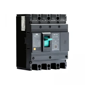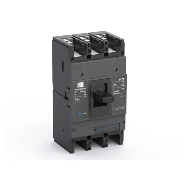
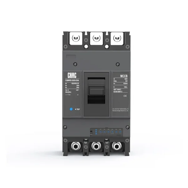
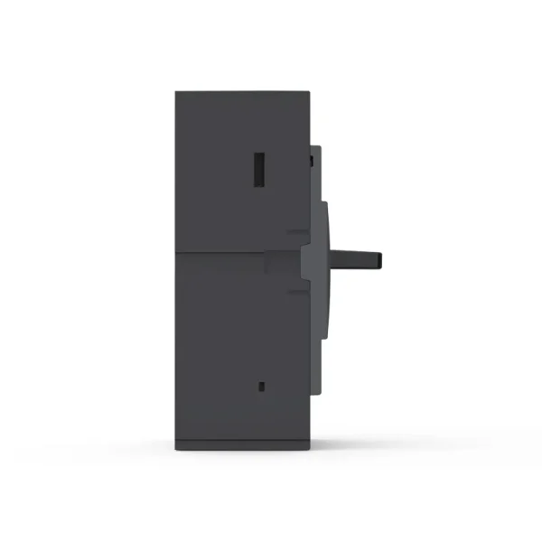
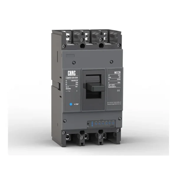
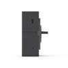
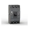
Fabricante OEM de interruptores automáticos en caja moldeada (MCCB) electrónicos ajustables CQM6E
El CQM6E MCCB provides adjustable overload, short circuit and ground-fault protection within its published 10–1250A range. Specification should follow the system voltage, load, conductor coordination, prospective fault current and applicable rules—not the ampere value alone.
Descripción del producto
CQM6E is a mccb circuit breaker for AC 400/415V distribution and protection applications. Its published range covers 10–1250A with 3P / 4P options. Selection depends on the complete power-system design, including fault level, coordination, conductor ampacity, enclosure conditions and local rules.
The saved model record lists IEC/EN 60947 and GB/T 14048 references listed on the page as the applicable standard reference. No certification claim is added beyond the model record.
Características clave
Aplicaciones típicas
Typical applications include industrial automation, critical feeders and systems that require adjustable selectivity or monitoring. These are evaluation contexts rather than universal approvals. Confirm the exact frame, voltage, breaking duty, trip unit, accessories and installation method before specification.
Guía de Solicitudes y Selección
Use the verified CQM6E values below to create a shortlist, then validate the complete circuit. An MCCB rating does not replace conductor calculations, fault-current analysis, coordination review or local installation requirements.
| Punto de selección | CQM6E reference | Lo que el proyecto debe confirmar |
|---|---|---|
| Corriente nominal | 10–1250A | Design current, conductor ampacity, installation method, temperature and grouping |
| Voltaje | AC 400/415V | Sistema de suministro y capacidad nominal de los equipos |
| Polacos | 3P / 4P | Live conductors and neutral treatment |
| Trip / protection | adjustable electronic L-S-I-G protection | Load profile, fault response and coordination |
| Capacidad de corte | S/M/H classes up to 75kA, according to frame and ordered configuration | Prospective short-circuit current at the installation point |
Electronic vs Thermal-Magnetic Trip
Electronic trip units can provide adjustable thresholds and additional monitoring functions. Confirm the actual setting range, auxiliary supply and coordination study for the ordered model.
Protection Settings
Review Electronic MCCBs →
MCCB vs MCB
An MCCB is normally evaluated for higher current, fault duty or accessory flexibility; an MCB may be more suitable for compact final circuits.
Current & Fault Duty
Compare MCCB and MCB →
Icu vs Ics
The saved data for CQM6E lists S/M/H classes up to 75kA, according to frame and ordered configuration. Match the declared duty to the prospective short-circuit current and continuity objective.
Short-Circuit Study
Review Technical Support →
Pole and Neutral Arrangement
Published pole options are 3P / 4P. Confirm which conductors must be switched, protected and isolated together.
System Arrangement
View MCCB Range →
Guía de pedidos
- State the exact model: CQM6E.
- Provide frame and rated current within the published range: 10–1250A.
- Confirm poles: 3P / 4P.
- Specify the trip unit or protection function: adjustable electronic L-S-I-G protection.
- Provide system voltage, frequency, application, expected fault level, destination market and quantity.
- List required accessories, terminals, documents and any approved OEM/ODM marking or packaging requirements.
Comprobaciones de Instalación y Coordinación
- Use the exact model drawing and instructions; do not infer terminal positions, supply direction or accessory compatibility from another MCCB.
- Verify conductor material and cross-section against the circuit calculation, terminal data, temperature and grouping.
- Confirm Icu/Ics or DC fault duty, upstream/downstream coordination, enclosure conditions, altitude and clearances.
- Installation, isolation, testing and maintenance must be performed by qualified personnel under applicable rules.
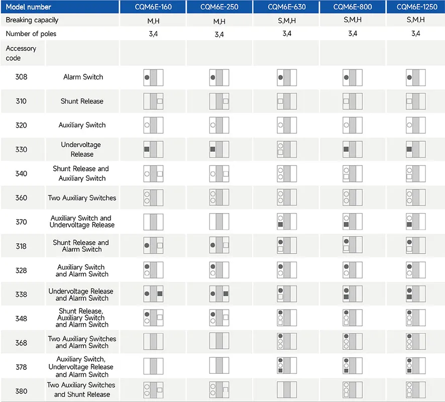
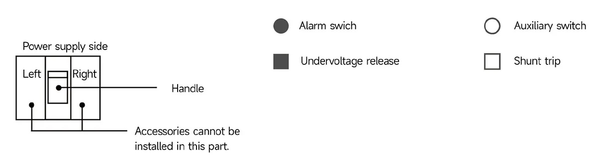
Lista de accesorios
Characteristic curve
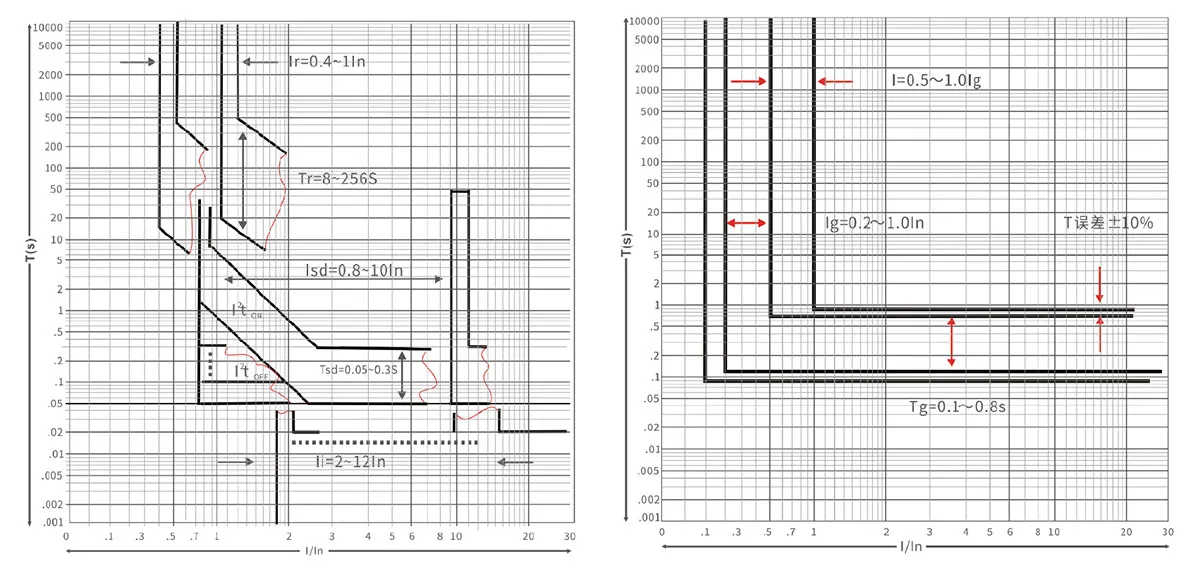
Guía de selección

| Product code① | Shell frame grade② | Shell frame rating current optional designator③ | Breaking capacity④ | |||
| CQM6 | E | 160 | S | M | H | |
| Molded case circuit breaker | E Electronically Adjustable |
160 | 160 | / | 50/35 | 50/50 |
| 250 | 250 | / | 50/35 | 50/50 | ||
| 630 | 630 | 35/25 | 50/35 | 75/75 | ||
| 800 | 800 | 35/25 | 50/35 | 75/75 | ||
| 1250 | 1250 | 35/25 | 50/35 | 75/75 | ||
| Operating method ⑤ | Number of poles ⑤ | Método de desacoplador y accesorios internos ⑥ | Corriente nominal A ⑦ |
| P | 4 | 300 | 160A |
| P: Motorized operation Z: Turn the handle W: Direct operation |
tripolar tetrapolar |
2: Intelligent disconnectors Note: The last two digits are the accessory code (see attachment) |
160, 250, 630, 800, 1250 |
| Función ⑧ | Four-pole products can be selected code ⑨ | Código especial ⑩ |
| 2 | A | I |
| 1: For power distribution 2: For motor protection |
A: N-pole without protection, can not be combined B: N-pole with protection, can be combined C: N-pole with protection, can be combined D: N-pole with protection, can not be combined Note: If the customer does not have a clear request, four-pole products will be defaulted to the B category |
I: Overload alarm non-trip function |
Main Technical Parameters
| Número de modelo | CQM6E-160 | CQM6E-250 | ||||
| Rated current of frame level Inm(A) | 160 | 250 | ||||
| Número de polos | 3, 4 | 3, 4 | ||||
| Rated current In(A),at 40℃,50℃,55℃ | 32, 63, 125, 160 | 160, 250 | ||||
| Rated operating voltage Ue(V),AC 50/60Hz | 400/415 | 400/415 | ||||
| Rated insulation voltage Ui (V) | 800 | 800 | ||||
| Rated impulse withstand voltage Uimp(KV) | 8 | 8 | ||||
| Breaking capacity designation | M | H | M | H | ||
| Short-circuit breaking capacity Icu/Ics(kA) | AC400/415V | 50/35 | 50/50 | 50/35 | 50/50 | |
| Rated short-time withstand current Icw(kA),1s | AC400/415V | 2 | 2 | 5 | 5 | |
| Selectivity category | B | B | B | B | ||
| Number of operating cycles (cycle) | ON | 6000 | 6000 | |||
| OFF | 10000 | 10000 | ||||
| Electronic decouping (adjustable) | Power distribution protection | ● | ● | ● | ● | |
| Motor protection | ● | ● | ● | ● | ||
| Accessory | Auxiliary contacts | ● | ● | ● | ● | |
| Alarm contacts | ● | ● | ● | ● | ||
| Shunt disconnect | ● | ● | ● | ● | ||
| Undervoltage detent | ● | ● | ● | ● | ||
| Manual operating mechanism | ● | ● | ● | ● | ||
| Motorized operating mechanism | ● | ● | ● | ● | ||
| Backplane wiring | ● | ● | ● | ● | ||
| Inserted | ● | ● | ● | ● | ||
| Coupling plate | ● | ● | ● | ● | ||
| Partition between phases | ● | ● | ● | ● | ||
| Overall dimensions (mm) (a-b-c-ca) | 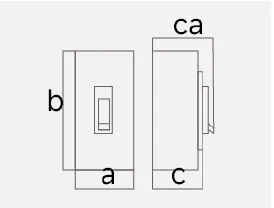 |
3P | 90-155-84-109 | 105-165-93-120 | ||
| 4P | 120-155-84-109 | 140-165-93-120 | ||||
Note:● for optional accessories;”-” for no optional accessories.
| Número de modelo | CQM6E-630 | CQM6E-800 | CQM6E-1250 | ||||||||
| Rated current of frame level Inm(A) | 630 | 800 | 1250 | ||||||||
| Número de polos | 3, 4 | 3, 4 | 3, 4 | ||||||||
| Rated current In(A), at 40℃, 50℃, 55℃ | 400, 630 | 630, 800 | 1000, 1250 | ||||||||
| Rated operating voltage Ue(V), AC 50/60Hz | 400/415 | 400/415 | 400/415 | ||||||||
| Rated insulation voltage Ui (V) | 800 | 800 | 800 | ||||||||
| Rated impulse withstand voltage Uimp(KV) | 8 | 8 | 8 | ||||||||
| Breaking capacity designation | S | M | H | S | M | H | S | M | H | ||
| Short-circuit breaking capacity Icu/Ics(kA) | AC400/415V | 35/25 | 50/35 | 75/75 | 35/25 | 50/35 | 75/75 | 35/25 | 50/35 | 75/75 | |
| Rated short-time withstand current Icw(kA), 1s | AC400/415V | 8 | 8 | 8 | 10 | 10 | 10 | 19.2 | 19.2 | 19.2 | |
| Selectivity category | B | B | B | B | B | B | B | B | B | ||
| Number of operating cycles(cycle) | ON | 3000 | 3000 | 1000 | |||||||
| OFF | 8000 | 8000 | 3000 | ||||||||
| Electronic decouping (adjustable) |
Power distribution protection | ● | ● | ● | ● | ● | ● | ● | ● | ● | |
| Motor protection | ● | ● | ● | ● | ● | ● | ● | ● | ● | ||
| Accessory | Auxiliary contacts | ● | ● | ● | ● | ● | ● | ● | ● | ● | |
| Alarm contacts | ● | ● | ● | ● | ● | ● | ● | ● | ● | ||
| Shunt disconnect | ● | ● | ● | ● | ● | ● | ● | ● | ● | ||
| Undervoltage detent | ● | ● | ● | ● | ● | ● | ● | ● | ● | ||
| Manual operating mechanism | ● | ● | ● | ● | ● | ● | ● | ● | ● | ||
| Motorized operating mechanism | ● | ● | ● | ● | ● | ● | ● | ● | ● | ||
| Backplane wiring | ● | ● | ● | ● | ● | ● | ● | ● | ● | ||
| Inserted | ● | ● | ● | ● | ● | ● | ● | ● | ● | ||
| Coupling plate | ● | ● | ● | ● | ● | ● | ● | ● | ● | ||
| Partition between phases | ● | ● | ● | ● | ● | ● | ● | ● | ● | ||
| Overall dimensions | 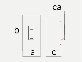 |
3 P | 140-257-105-155 | 210-275-105-155 | 210-275-105-155 | ||||||
| (mm) (a-b-c-ca) | 4 P | 185-257-105-155 | 280-275-105-155 | 280-275-105-155 | |||||||
Note:● for optional accessories;”-” for no optional accessories.
Intlligent Release Adjustment Panel
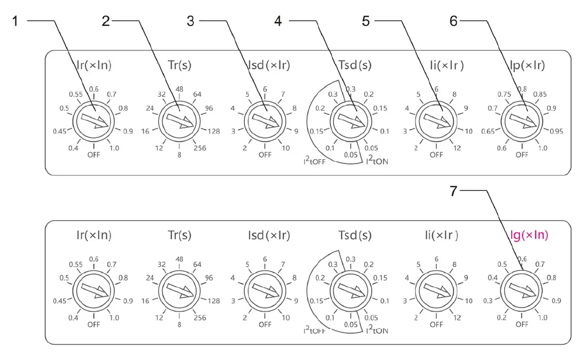
1.Ir: Rated Current (Ir) Setting Dial
The setting dial for the rated current, applicable to 160-1250 frame sizes. The selectable settings on the front panel are:0.4, 0.45, 0.5, 0.55,0.6, 0.7,0.8,0.9,1.0, OFF.
2.Tr. Long-Time Delay (Tr) Setting Dial
The setting dial for the overload long-time delay. When the current passing through the circuit breaker reaches 1.5 times lr (×in), the breaker trips within the set time.
The selectable settings are: 8s, 12s, 16s, 24s, 32s, 48s, 64s, 96s, 128s,256s.
3.Isd: Short-Time Delay Current (Isd) Setting Dial
The setting dial for the short-time delay current multiplier. Selectable setting are: 2,3, 4, 5, 6,7,8, 9, 10, OFF. When a short-circuit current equal to the set value(×Ir, ×In) passes through the breaker, it will trip after a time delay.
4.Tsd: Short-Time Delay Operating Time (Tsd) Setting Dial
The setting dial for the short-time delay operating time. It is divided into inverse-time protection (2t ON) and definite-time protection (2t OFF). Selectable settings are: 0.05s, 0.1s, 0.15s, 0.2s, 0.3s. When a short-circuit current equal tosses through the breaker, it will trip within the set time.
5.li: Instantaneous Current (Ii)Setting Dial
The setting dial for the instantaneous current multiplier. Selectable settare:2,3,4,5,6,8,9,10,12. When a short-circuit current equal to the set value (×in) passes through the breaker, it will trip instantaneously.
6.Ip: Pre-alarm Current(Ip) Setting Dial
The setting dial for the pre-alarm current multiplier. Selectable settings are:60%,65%,70%, 75%, 80%, 85%, 90%, 95%, 100%, OFF. When the current passing through the breaker reaches the set value (×ir, ×in), the pre-alarm indicator light will illuminate.
7.Ig: Ground Fault Current (Ig) Setting Dial
The setting dial for the ground fault current multiplier. Selectable setting are:0.2,0.3, 0.4, 0.5, 0.6, 0.7, 0.8, 0.9, 1.0,OFF. When the ground fault current passing through the breaker reaches the set value (×In),the breaker will trip due to the ground fault.
Characteristics of Intelligent Release: It has protection functions such as overload long-delay inverse time, short-circuit short-delay inverse time,short-circuit short-delay fixed time,and short-circuit instantaneous action. These functions can be set by the user to form the required protection characteristics. The inverse time action characteristics of long-delay overcurrent protection are shown in the table:
| Current | time of action | ||
| power distribution |
1.05lr | >2h inoperative(In>63A),1h inoperative (In≤63A) | |
| 1.3r | <1h action | ||
| 1.5lr | Settling time tr(s) | Inm-125A、250A、400A、630A、800A、1250A | |
| 8、12、16、24、32、48、64、96、128、256 | |||
Remarks:Tolerance of operation value is ±10%,tolerance of operation time is ±15%.
Short delay overcurrent protection action characteristics
When Tsd is within the 12tON stall range,it is a fixed time limit:
| Current | time of action | |||||
| I≤Isd≤6Ir counter-time limit | I²T2=(6Xlr)² Tsd | |||||
| I>Isd and I>6Ir Inverse time limit to fixed time limit |
Consolidation time | 0.05 | 0.1 | 0.15 | 0.2 | 0.3 |
| Inaccuracies | ±0.02 | ±0.03 | ±0.04 | ±0.06 | ±0.08 | |
| Returnable time | – | – | 0.14 | 0.21 | 0.3 | |
Remarks :1 is the actual passing current, T2 is the actual action time,lsd is the set short delay curent, Tsd is the set short delay action time
When Tsd is in the range of I2tOFF gear,it is fixed time limit:
| Current | time of action | |||||
| l≥lsd Current Error±10% | Consolidation time | 0.05 | 0.1 | 0.15 | 0.2 | 0.3 |
| Inaccuracies | ±0.02 | ±0.03 | ±0.04 | ±0.06 | ±0.08 | |
| Returnable time | – | – | 0.14 | 0.21 | 0.3 | |
Remarks:lis the actual passing current,T2 is the actual action time;lsdis the short delay curent, Tsd is the short delay actiontime.
Short-circuit transient protection action characteristics
| Current | li=(2,3,4,5,6,8,9,10,12)×ln | |
| Motion Characteristics | Operating current | Minimum operating current 0.9li Maximum inoperative current 1.1li |
| time of action | <0,1 s | |
Grounding protection operating characteristics
| Current | Ig=(0.2,0.3,0.4,0.5,0.6,0.7,0.8,0.9,1.0)×ln | |
| Motion Characteristics | Ig≤0.9lg Circuit breaker inoperative | Ig>1.1lg |
| time of action | Tg=0.4(fixed time limit) | |
The electronic striker panel indicators are set as follows
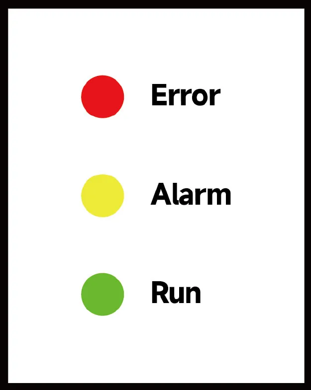
Overload pre-warning characteritics:
| Load Current | I<1lp | I > 1lp |
| Indicator status | Indicator ligh is not flashing,does not light up | Indicator light constant |
| Load Current | I<1.15lp | I ≥ 1.15lp |
| Indicator status | Indicator light is not on | Indicator ligh is on |
| Load Current | ≥0.4In(Single phase) | l≥0.2ln(Tri-phase) |
| Indicator status | Indicator light is on | Indicator light is on |
Nota:
1.The above current error±10%.
2.The pre-alarm current needs to satisfy the startup current constraint,i.e.,the current cannot be lower than the operating condition.
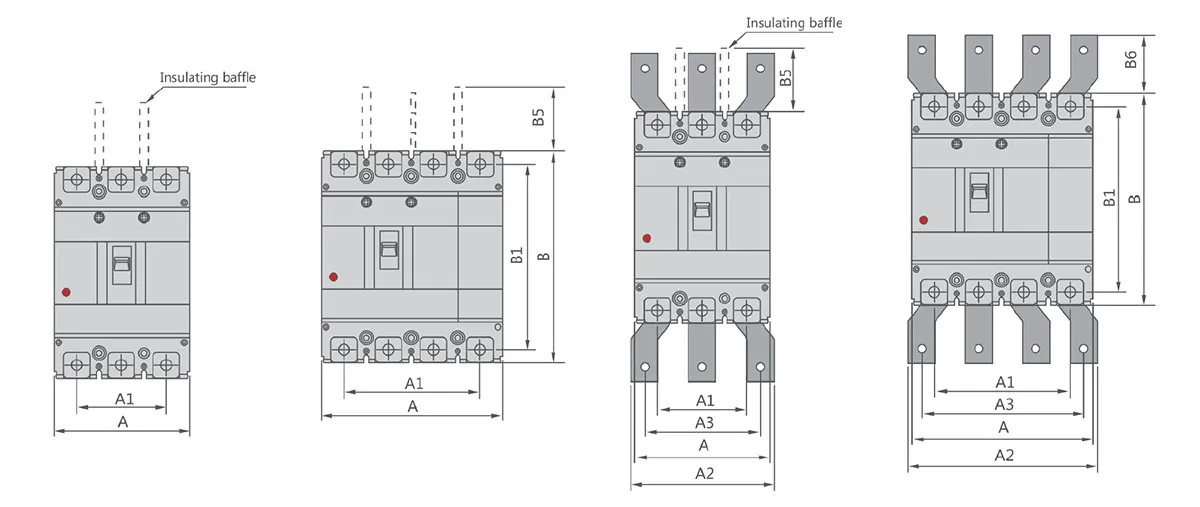
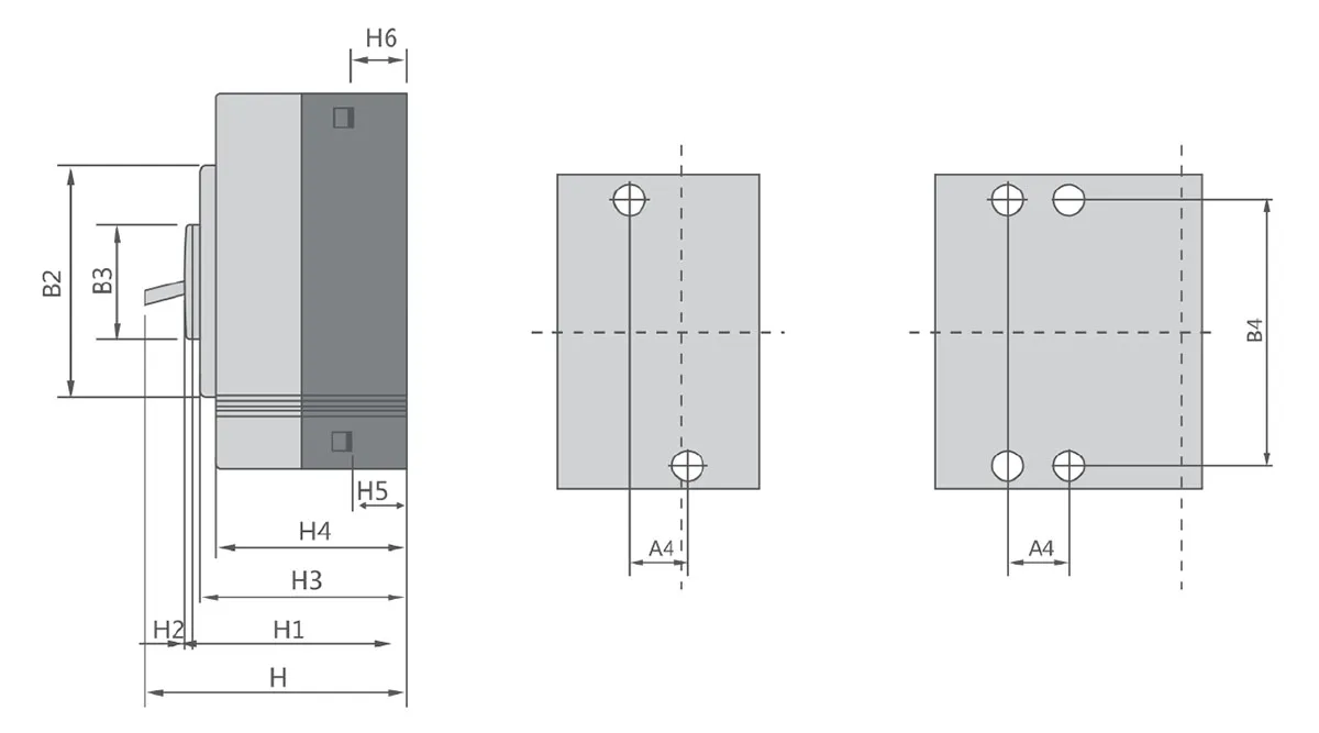
Outline and Installation Dimensions(mm)
| Molded case circuit breaker | Overall dimension | Installation dimensions | Bolt | |||||||||||||||||||||
| A | A1 | A2 | A3 | B | B1 | B2 | B3 | B5 | B6 | H | H1 | H2 | H3 | H4 | H5 | H6 | A4 | B4 | ||||||
| 3P | 4P | 3P | 4P | 3P | 4P | 3P | 4P | |||||||||||||||||
| CQM6E-160 | 90 | 120 | 60 | 90 | – | – | – | – | 155 | 134 | 102 | 50 | 50 | – | 109 | 83 | 4 | 83 | 76 | 24.5 | 24.5 | 30 | 132 | M8 |
| CQM6E-250 | 105 | 140 | 70 | 105 | – | – | – | – | 165 | 144 | 102 | 50 | 110 | – | 120 | 95 | 4 | 91 | 84 | 22.5 | 24 | 35 | 126 | M8 |
| CQM6E-630 | 140 | 185 | 88 | 132 | 140 | 196 | 112 | 196 | 257 | 230 | 179 | 90 | 110 | 42 | 155 | 107 | 5 | 105 | 97 | 30 | 32 | 44 | 194 | M10 |
| CQM6E-800 | 210 | 280 | 140 | 210 | 180 | 250 | 140 | 250 | 275 | 243 | 192 | 90 | 110 | 87 | 155 | 107 | 5 | 104 | 97 | 25 | 25 | 70 | 242.5 | M12 |
| CQM6E-1250 | 210 | 280 | 140 | 210 | 180 | 250 | 140 | 250 | 275 | 243 | 192 | 90 | 110 | 87 | 155 | 107 | 5 | 104 | 97 | 25 | 25 | 70 | 242.5 | M10*2 |
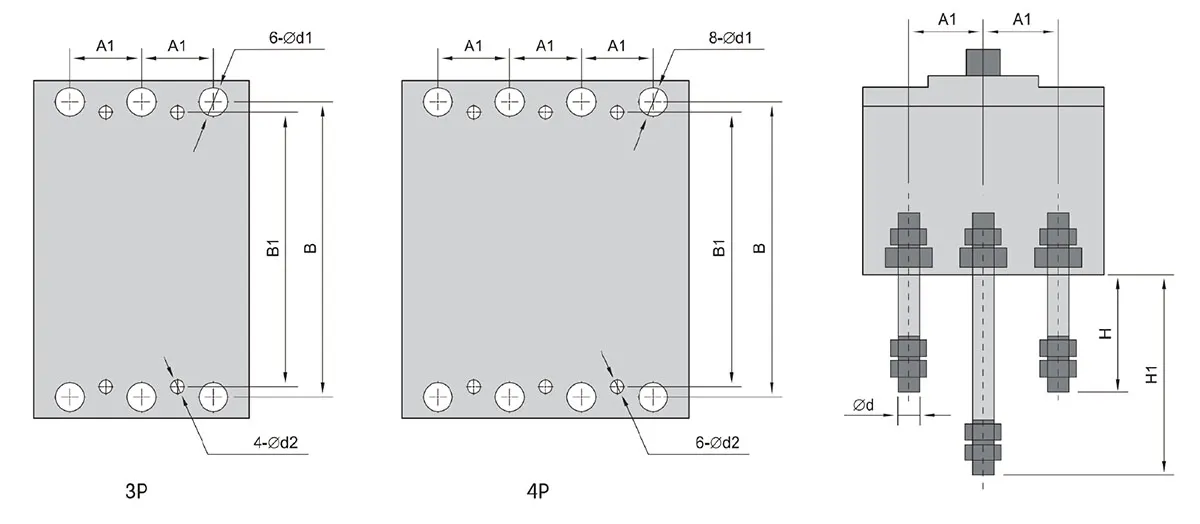
Appearance and instllation dimensions at the rear of the panel
Appearance and installation dimensions of the rear part for the plug-in type(on the panel)
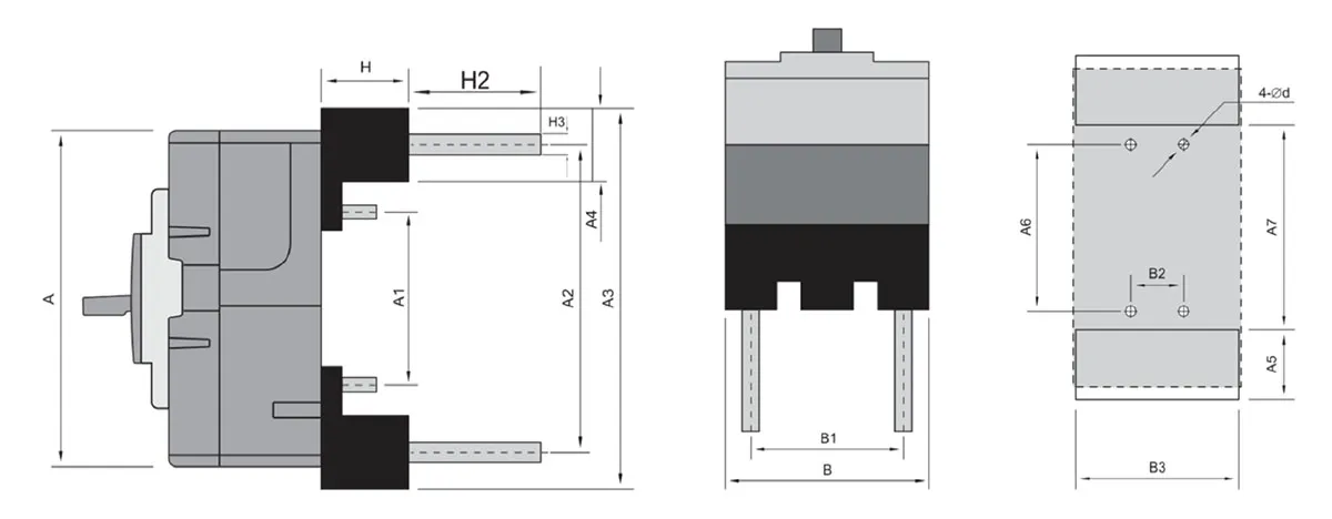
| Molded case circuit breaker | B-board rear wiring dimensions | C Front-of-Board Wiring Dimensions | C Plug-in wiring size | ||||||||||||||||||||||||
| A1 | B | B1 | H | H1 | φd | φd1 | φd2 | φd3 | A4 | B4 | A | A1 | A2 | A3 | A4 | A5 | A6 | A7 | H | B | B1 | B2 | B3 | φd | H2 | H3 | |
| 125 | 25 | 114 | 111 | 62 | 87 | 6 | 14 | 5 | 5 | 25 | 111 | 130 | 58 | 115 | 132 | 17.5 | 20 | 58 | 97 | 28 | 75 | 50 | 50 | 77 | 5.5 | 15 | 10.5 |
| 160 | 30 | 134 | 132 | 72 | 112 | 8 | 18 | 5 | 5 | 30 | 132 | 155 | 60 | 134 | 173 | 38 | 40 | 60 | 98 | 50 | 92 | 60 | 60 | 94 | 6.5 | 31 | 19.5 |
| 250 | 35 | 144 | 126 | 87 | 126 | 12 | 24 | 5 | 5 | 35 | 126 | 165 | 54 | 144 | 184 | 45 | 47 | 54 | 95 | 50 | 107 | 70 | 70 | 109 | 6.5 | 35 | 21.5 |
| 630 | 44 | 230 | 194 | 83 | 136 | 18 | 35 | 7 | 7 | 44 | 194 | 257 | 125 | 225 | 280 | 55 | 57 | 125 | 169 | 60 | 140 | 87 | 60 | 142 | 9 | 32 | φ23 |
| 800 | 70 | 243 | 243 | 174 | 243 | 26 | 48 | 7 | 7 | 70 | 243 | 275 | 147 | 242 | 42 | 55 | 58 | 147 | 190 | 91 | 218 | 140 | 107 | 222 | 10.5 | 31 | φ27 |
Appearance and installation dimensions of the rear part for the plug-in type(on the panel)
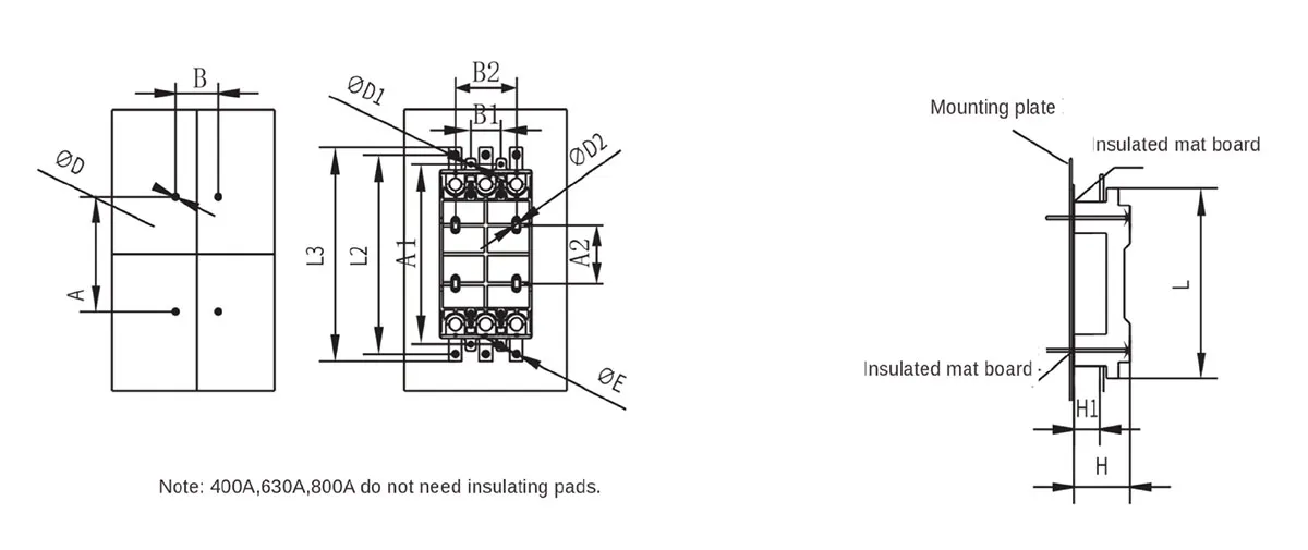
| Model Number | A | E | L2 | L3 | D | E | H | H1 | L | A1 | B1 | D1 | A2 | B2 | D2 |
| 160 | 112 | 30 | 200 | 216 | 4.5 | 6.5 | 56 | 28 | 182 | 172 | 30 | 5.5 | 67 | 60 | 6.5 |
| 250 | 150 | 35 | 233 | 245 | 4.5 | 8.5 | 74 | 33 | 202 | 191 | 35 | 5.5 | 74 | 70 | 6.5 |
| 630 | 283 | 70 | 363 | 405 | 6.5 | 12.5 | 125 | 67 | 341 | 327 | 70 | 6.5 | 143 | 140 | 7 |
| 800 | 283 | 70 | 363 | 405 | 6.5 | 12.5 | 125 | 67 | 341 | 327 | 70 | 6.5 | 143 | 140 | 7 |
The internal accessories of CQM6E series include under-voltage detent,shunt detent, auxiliary alarm detent,its main technical paraameters and wiring diagrams are as follows.
Under-voltage release device
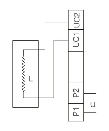
| Internal accessories | |
| Rated voltage of the power supply | Main Performance |
| AC220,AC240 AC380,AC415 |
A. When the supply voltage drops to 70%and 35%of the rated voltage, the undervoltage detector shall operate. B. When the electro-hydraulic voltage is lower than 35%of the rated voltage,the undervoltage detractor should not be able to absorb,in order to prevent the circuit breaker from closing. C.When the power supply voltage is equal to or greater than 85% of the rated voltage,the undervoltage detractor will ensure the absorption, and ensure the reliable closing of the circuit breaker. |
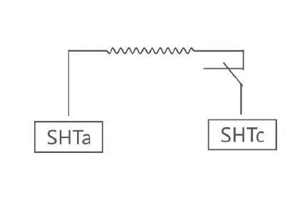
| Shunt release device | |
| Rated supply voltage | Main Performance |
| DC24,DC110 AC220,AC3B0 |
The shunt release can operate reliably between 70%and 110%of the rated voltage value. |
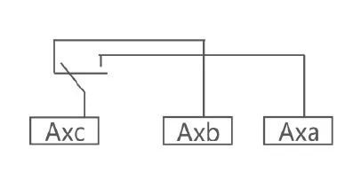
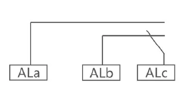
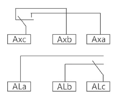
| Auxiliary alarm contact | |
| Rated voltage of power supply | Main performance |
| Auxiliary switch AC 125V 5A,AC 250V 3A DC 125V 0.4A,DC 125V 0.2A |
Provides differentiated signals for circuit breakers in the”closed” and “open”positions. |
| Alarm switch AC 125V 5A,AC 250V 3A DC 125V0.4A,DC 125V 0.2A |
Provides signals to distinguish between “normal operation and “fault free release” positions of circuit breakers. |
| Auxiliary alarm switch AC 125V 5A.AC 250V 3A DC 125V 0.4A,DC125V 0.2A |
Provides signals to distinguish between “closed”, “open” and “fault free release” positions of the circuit breaker. |
Internal accessory
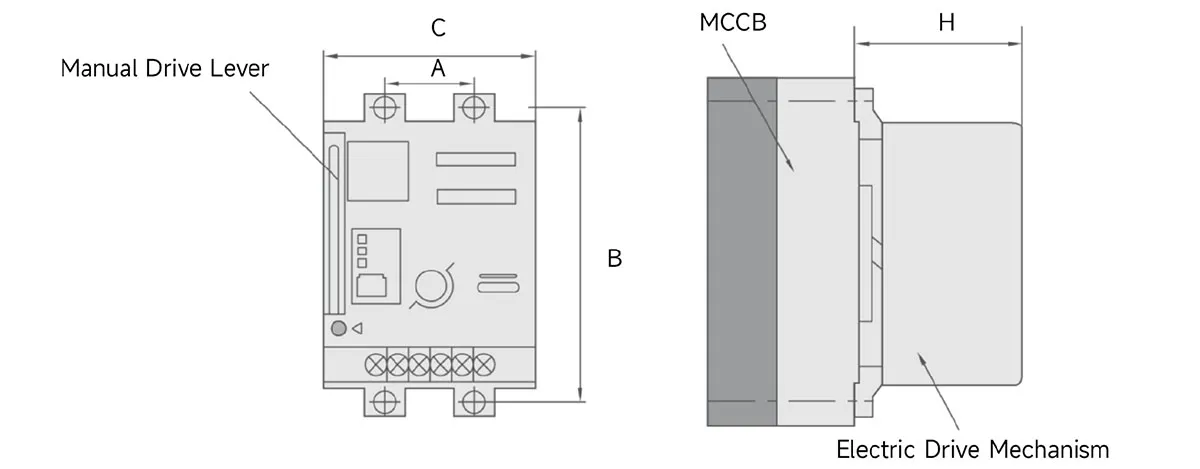
DC3 Electric Operation Mechanism
DC3 series electric operation mechanism is adopted advanced switching power supply technology,utilizing smallpermanent contact motordrive,small working current,suitable for 63-800A plastic case circuit breakers.
| Model Number | DC3-125 | DC3-160 | DC3-250 | DC3-630 | DC3-800 | |
| Compatible Modelo |
CQM6-125 | CQM6-160 CQM6RT-160 CQM6RE-160 |
CQM6RE-250 CQM6-250 CQM6L-250 CQM6RT-250 CQM6Z-250 |
CQM6-630 CQM6L-630 CQM6RT-630 CQM6RE-630 CQM6Z-630 |
CQM6-800 CQM6L-800 CQM6RT-800 CQM6RE-800 CQM6L-1250 CQM6RE-1250 |
|
| Overall Dimensions |
A | 25 | 30 | 35 | 44 | 70 |
| B | 117 | 132 | 126 | 194 | 243 | |
| C | 73 | 90 | 90 | 130 | 130 | |
| H | 98 | 98(89.5) | 102(92) | 152 | 153 | |
| Rated voltated V |
AC-110-240, DC100-220,DC24 |
AC 230,DC 220 AC 100,DC 110 |
||||
| Starting current A | ≤0.5 | ≤2 | ||||
| Mechanical life(times) | 14000 | 10000 | 5000 | |||
| Power(W) | 14 | 35 | ||||
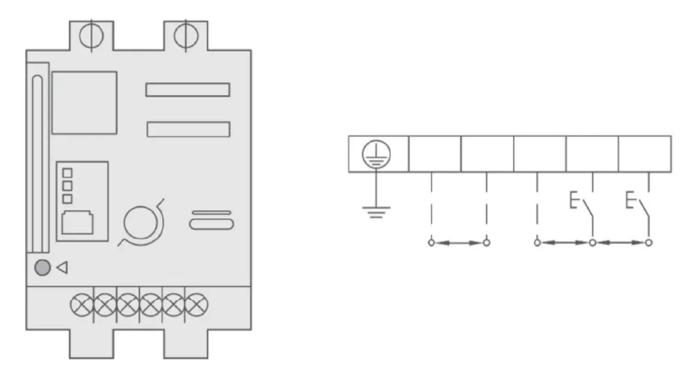
1.Manual operation:Counterclockwse operationis prohibited.
2.When operating manually,insert the handle at the starting point and turn it 180° in a clockwise direction.
Manual operating mechanism
Shape of the circular handle and the door panel opening size (the distance from the center of the opening to the hinge should not be less than 200mm)
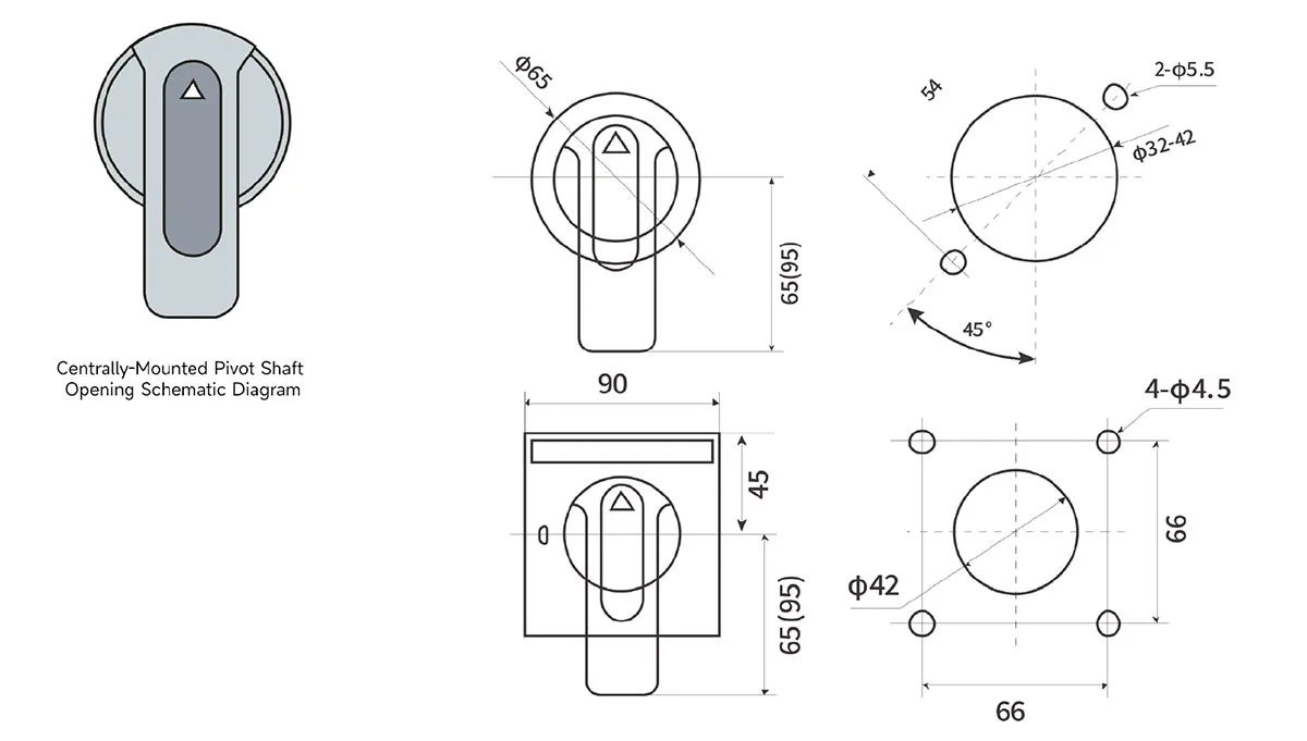
Outline and Installation Schematic Diagram of the Central Series Manual Opion Mechanism
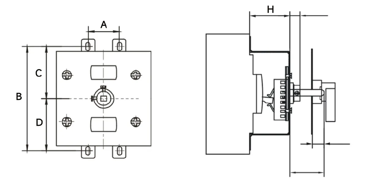
| Hand-operated mechanism model | A | B | C | D | H |
| 160 | 30 | 132 | 66 | 66 | 46 |
| 250 | 35 | 126 | 63 | 63 | 51 |
| 630 | 128 | 194 | 97 | 97 | 76 |
| 800 | 198 | 243 | 121.5 | 121.5 | 76 |
| 1250 | 198 | 243 | 121.5 | 121.5 | 76 |
¿Por qué elegir CHAC?
Con más de 30 años de experiencia en fabricación, más de 1100 empleados, más de 100 millones de postes
Con una capacidad anual y un proceso de producción automatizado 90%, CHAC ofrece una capacidad de producción estable y un estricto
control de calidad para clientes OEM/ODM globales. Nuestro sistema de fabricación interno respalda a largo plazo
Cooperación para marcas eléctricas, importadores y distribuidores.

30+
AÑOS DE EXPERIENCIA
Especializado en fabricación eléctrica de bajo voltaje

1100+
EMPLEADOS
Equipo profesional garantiza calidad y entrega estables

100M+
CAPACIDAD ANUAL DE LOS POLOS
Capacidad de producción a gran escala para satisfacer la demanda mundial

90%
PRODUCCIÓN AUTOMATIZADA
Automatización avanzada para alta eficiencia y consistencia
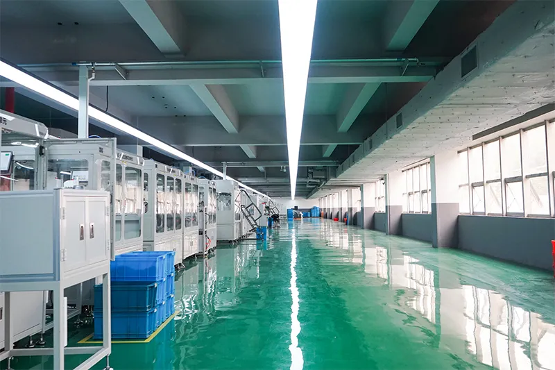
Línea de ensamblaje automatizada

Laboratorio de pruebas
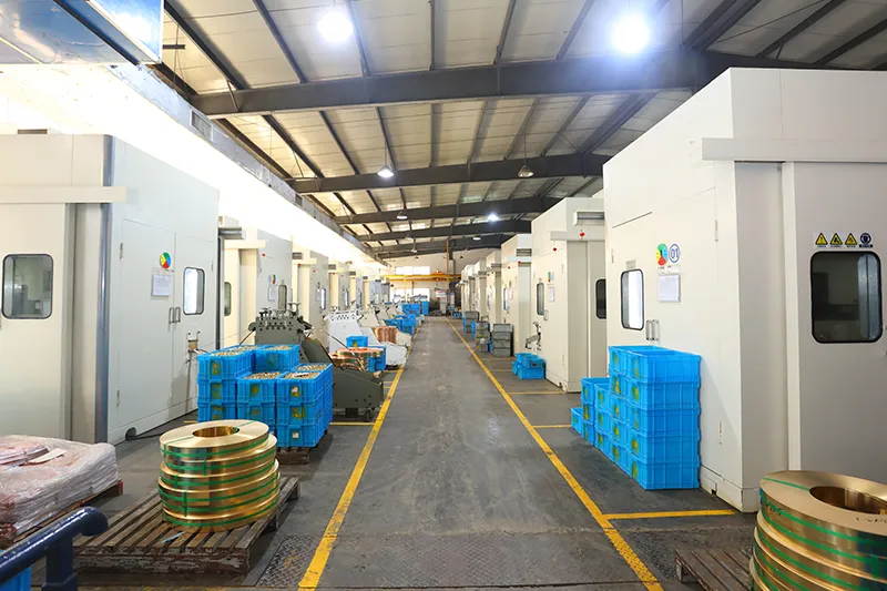
Inyección y Estampado
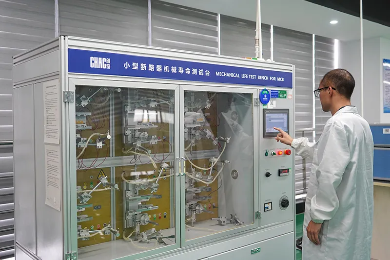
Inspección de calidad



Un estricto sistema de control de calidad garantiza que cada producto cumpla con los estándares mundiales.
¿Qué podemos personalizar?
For CQM6E projects, CHAC can review private-label marking, packaging, approved appearance options, published 10–1250A electrical configurations and technical-document requirements. Requests outside the published range are subject to engineering evaluation, testing, minimum order quantity and project feasibility.

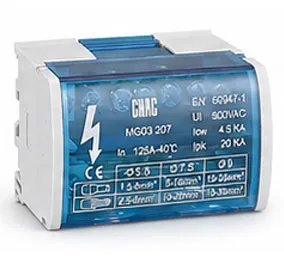
Recinto
Diseño
Tamaños, estructuras y detalles de instalación de recintos personalizados.
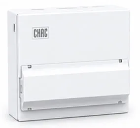

Interno
Configuración
Opciones flexibles de diseño interno y disposición de componentes.
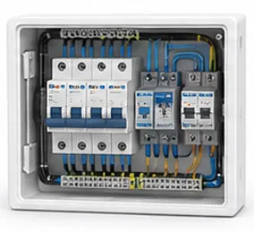

Marca e
Logo
Logotipos de marca propia, placas de identificación e identificación de marca.

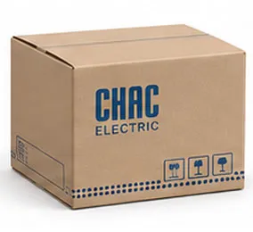
Empaquetado
Diseño
Soluciones de embalaje, cajas personalizadas, etiquetas y manuales.

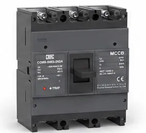
Eléctrico
Configuración
Instalación eléctrica adaptada a los requisitos de la aplicación.

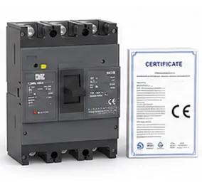
Certificación
Apoyo
Soporte para estándares del mercado objetivo y requisitos de cumplimiento.
Descargar
Interruptor automático de caja moldeada serie CQM6
Descripción general completa de componentes eléctricos de bajo voltaje y referencia para la selección de productos.
¿Necesita documentos técnicos?
Contáctenos para obtener hojas de datos, certificados, planos, orientación de selección o soporte para proyectos OEM/ODM.
CQM6E Product FAQ
What is the CQM6E MCCB used for?
The CQM6E is specified for adjustable overload, short circuit and ground-fault protection in AC 400/415V systems within the published 10–1250A range. Suitability depends on the fault study, conductor coordination, enclosure and local rules.
What does the electronic trip unit do in the CQM6E?
The electronic trip unit processes current signals and provides the adjustable protection functions stated for the model. Confirm the available long-time, short-time, instantaneous, ground-fault, auxiliary-power and communication options for the ordered configuration.
How do I choose the CQM6E rated current and poles?
Start with the design current and conductor calculation, then choose a published current within 10–1250A and poles from 3P / 4P. Neutral treatment, fault level, ambient conditions and coordination also need review.
What breaking capacity should I check on the CQM6E?
Use the declared S/M/H classes up to 75kA, according to frame and ordered configuration for the exact frame, voltage and configuration. The prospective short-circuit current at the installation point must be within the applicable duty; a larger ampere value alone is not a selection rule.
Can the CQM6E replace an MCB or an earth-leakage device?
An MCCB is not automatically a like-for-like replacement. The CQM6E provides adjustable overload, short circuit and ground-fault protection; residual-current protection, DC interruption, adjustable settings and other functions must be confirmed separately from the project requirement.
How should the CQM6E be installed and tested?
Use only the exact model drawing, terminal identification and accessory instructions. A qualified person should verify isolation, conductor size, torque, clearances, settings, fault duty and functional tests before energising the circuit.
Confirm the Right CQM6E Configuration
Send the frame, rated current, poles, protection function, system voltage, expected fault level, destination market and quantity. CHAC will review the request against the published model range.