When Elena, a solar EPC engineer in Seville, encountered a breaker that tripped as soon as a newly commissioned PV string was energized on a cold morning, she replaced it with the same nominal current rating and saw the failure return within minutes. In this illustrative scenario, the reversal came when the team checked the string’s cold-temperature maximum voltage and the breaker connection diagram: the problem was selection and pole configuration, not simply a defective product.
Resumen: Select a interruptor automático de corriente continua from the circuit’s maximum voltage, continuous design current, conductor limit, prospective fault current, polarity, pole configuration and isolation plan—not from panel wattage alone. IEC 60947-2:2024 covers circuit-breakers within its scope up to 1,500 V DC, but that scope does not make every breaker suitable for every PV circuit. Calculate the project inputs, identify the source and fault-current direction, then verify the exact model rating and connection instructions before approval.
Which Voltage, Current, and Fault Data Should You Collect First?
A breaker ampere value is only one part of the decision. The maximum voltage must cover the highest voltage that can appear across the device in the intended installation. For a PV string, that means checking the open-circuit voltage at the lowest project design temperature using the module manufacturer’s voltage-temperature data and the applicable design method. The operating voltage printed at standard test conditions is not the cold-weather maximum.
Current requires a similarly disciplined path. Start from the source data and circuit architecture, apply the design method required for the destination project, and verify that the selected protective setting or rating does not exceed the protected conductor’s allowable current under the actual installation and ambient conditions. Panel watts divided by a nominal voltage can be a useful load estimate in some contexts, but it does not establish maximum PV voltage, source short-circuit current, conductor capacity, reverse-current exposure or the breaker’s required interrupting duty.
| Calculation or verification input | Evidence to record | Decision it supports | Approval boundary |
|---|---|---|---|
| Maximum circuit voltage | Series module count, module open-circuit voltage and temperature coefficient, lowest design temperature, or source maximum output | Required DC voltage rating and permitted pole arrangement | Use the applicable project method; do not substitute nominal operating voltage |
| Continuous design current | Module short-circuit current or source/load data, parallel paths, expected duty and destination design rules | Breaker current rating or setting | No universal multiplier fits every jurisdiction, source or product |
| Conductor allowable current | Conductor size, insulation, installation method, bundling, enclosure temperature and applicable correction factors | Upper boundary for overcurrent-device selection | Confirm from the governing wiring rules and conductor data |
| Prospective fault current | Protection study at the installation point, including contributing sources and direction | Required DC breaking capacity and coordination review | Do not infer battery or bus fault energy from PV-string behavior |
| Polarity and pole configuration | System grounding, conductor arrangement, one-line diagram and exact breaker connection diagram | Which conductors open and whether series poles are permitted or required | The model instructions control; another breaker’s diagram is not evidence |
| Installation conditions | Enclosure, ambient range, altitude, terminal/conductor limits and mounting orientation | Derating, fit and environmental suitability | Use published limits for the exact catalog number |
An illustrative calculation record should therefore show inputs and method before it shows a selected catalog number. If a module specification, minimum temperature, conductor condition or fault study is missing, the defensible result is “selection pending,” not a guessed rating. That pause prevents nuisance trips, overheated conductors, an underrated interrupting device and expensive field rework.
Why an AC Breaker Cannot Be Assumed Suitable for DC
An AC arc benefits from a natural current zero crossing; DC interruption does not have that same waveform condition. A breaker must therefore carry a published DC rating for the circuit voltage, current, breaking duty and connection arrangement. The related guide to DC MCB and AC circuit compatibility explains why an AC nameplate alone is not a safe approval basis.
| Dimension de selección | What must be matched | Cost of a weak assumption |
|---|---|---|
| Voltaje | Published DC voltage for the permitted wiring and pole arrangement | Selection may sit outside the device’s demonstrated interruption conditions |
| Current and conductor protection | Design current, device rating or setting, conductor limit and environmental derating | Nuisance operation or inadequate conductor protection |
| Capacidad de corte | Prospective fault current at the installation point | Rejected design, coordination failure or equipment replacement |
| Polarity and poles | Exact manufacturer’s terminal markings and approved series-pole connection | Miswiring, failed inspection or loss of the declared rating basis |
| Functional coverage | Overcurrent, isolation, surge, earth-fault and arc-fault functions mapped separately | A required protection function may be absent despite the breaker being correctly sized |
| Documentation | Traceable one-line, data sheet, instructions and final connection diagram | Procurement substitutions and commissioning errors become harder to detect |
How PV, Battery, and DC Distribution Circuits Differ
La frase solar DC breaker does not define one universal duty. A PV string is a current-limited source whose reverse-current exposure may come from other parallel strings or connected equipment. A battery can contribute high fault current in a different direction and time profile. A DC distribution bus may have several contributing sources and a coordination requirement with upstream and downstream devices. The source and current path must be drawn before the protective device can be assessed.
| System boundary | Current and fault question | Breaker review | Scope boundary |
|---|---|---|---|
| PV string or sub-array | What are the string operating current, source short-circuit current and possible reverse-current contributions from parallel paths? | Cold maximum voltage, conductor protection, polarity, pole arrangement and PV-source switching conditions | Apply PV-array design rules; record the array one-line and connection direction |
| Battery branch | What fault current can the battery and connected bus deliver, and from which side? | Interrupting rating, directional/polarity instructions, conductor protection and coordination near the source | IEC 62548-1 excludes energy storage devices; obtain battery-system engineering and applicable rules separately |
| DC distribution output | Which upstream sources contribute to a downstream fault, and is backfeed possible? | Breaking duty, selectivity, bidirectional suitability where required and load characteristics | A PV-array rule does not automatically govern the load/distribution network |
| PV-plus-storage interface | Can either the PV side, storage side or converter feed the fault location? | Assess each device at its actual terminals and operating state | Split the study at defined interfaces; do not merge unlike source assumptions |
This boundary matrix is a screening tool, not a short-circuit study. It makes one procurement risk visible: a part number acceptable on a PV string is not automatically acceptable on a battery feeder just because voltage and nominal current appear similar.
How Poles, Polarity, and Isolation Affect DC Breaker Selection
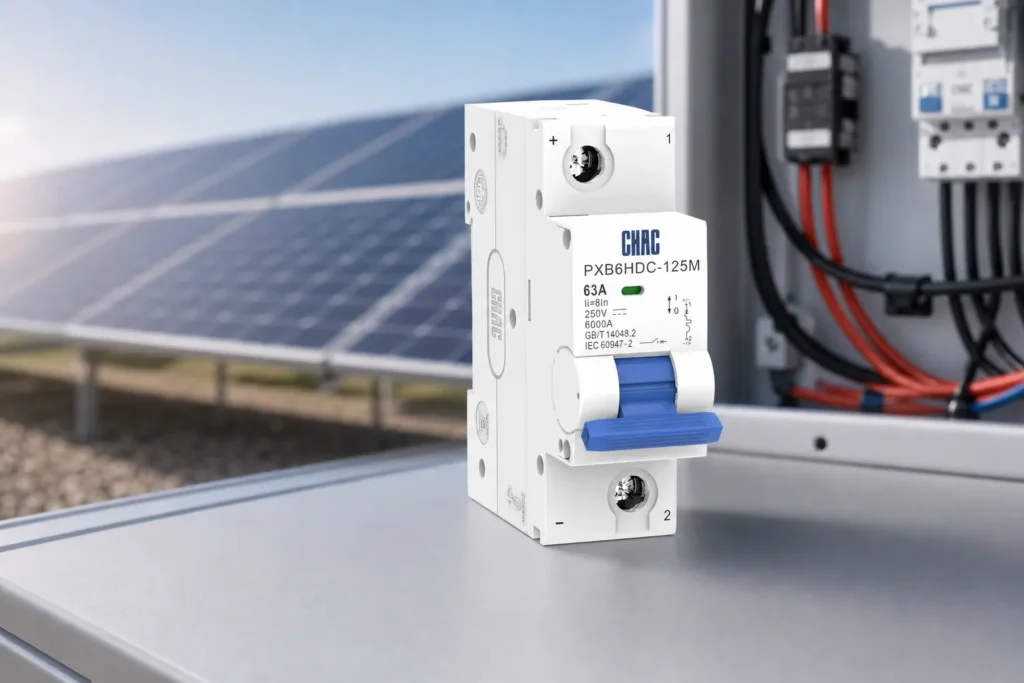
For PV circuit protection, pole count is not chosen by habit. It follows the system grounding arrangement, which conductors must be disconnected, the voltage across each pole and the exact device instructions. Where a manufacturer permits or requires poles in series to achieve a declared DC voltage, use only that documented connection. Never create a series-pole arrangement from a generic sketch or assume that a similar model has the same internal arc path.
Polarity markings also matter. Some DC breakers are polarity-sensitive; some applications require current to flow in more than one direction. Record the normal current direction and every credible fault contribution, then check the product documentation for the proposed terminal orientation and bidirectional suitability. If the data sheet is silent, obtain written clarification before approving the product.
| Function | Primary purpose | What the breaker selection does not prove |
|---|---|---|
| Overcurrent circuit-breaker function | Interrupt overload or fault current within declared ratings and conditions | That all required isolation, earth-fault or arc-fault functions are included |
| Disconnector / isolator | Provide the required isolation function for operation or maintenance | That it provides overcurrent protection or that every breaker is suitable for isolation |
| Surge protective device (SPD) | Limit specified transient overvoltage conditions as part of a coordinated design | That the breaker limits surges |
| Residual-current or earth-fault function | Detect the specified leakage or earth-fault condition | That ordinary overcurrent protection detects every earth fault |
| Arc-fault function | Detect and act on covered arc-fault signatures when explicitly provided | That a standard DC overcurrent breaker includes arc-fault detection |
A breaker may also provide switching or isolation capabilities when the exact product is designed, marked and installed for them, but the word “breaker” alone is not evidence. Treat the one-line diagram as the functional map: show overcurrent protection, isolation points, SPDs, residual-current or earth-fault measures and arc-fault equipment as separate items unless the selected product documentation explicitly combines them.
Which PV and Circuit-Breaker Standards Apply?
IEC 62548-1:2023+AMD1:2025 CSV addresses the design requirements for PV arrays, including DC wiring, electrical protection devices, switching and earthing provisions. The 2025 consolidated edition includes revisions concerning isolation, cables, earth-fault arrangements, bifacial and non-optimal orientation conditions, and arc-flash provisions. It excludes energy storage devices and load or distribution networks, so it must not be stretched into a battery-breaker approval method.
IEC 60364-7-712:2025, the third edition, covers selection and application requirements for PV electrical installations from the modules to the connection point. Its 2025 changes include battery-related installation requirements and direct battery, DC bus and DCU provisions. This installation scope is distinct from IEC 62548-1’s PV-array design scope; neither reference by itself establishes the rating or permitted wiring of a specific breaker.
IEC 60947-2:2024 covers circuit-breakers up to 1,500 V DC within its stated scope. That upper scope limit is not a rating for a specific catalog number, and citing the standard is not the same as demonstrating product certification, an installation voltage, breaking capacity or a permitted wiring configuration. Procurement should request the exact model declaration and test/documentation basis relevant to the destination market and intended use.
Non-compliance has a commercial cost beyond the breaker itself: design resubmittals, delayed inspection, panel rework, rejected substitutions and unclear liability after a field event. The project team should identify the destination rules, intended circuit role and marketing claims before asking a supplier to confirm documentation. No article can certify a project or product.
What to Include in a Solar DC Breaker RFQ
Use the following sequence to turn engineering data into a reviewable request:
- Freeze the one-line diagram and label the boundary as PV array, battery branch, converter interface or DC distribution.
- Attach the voltage, current, conductor and fault-current inputs, including temperature and installation assumptions.
- State the grounding arrangement, conductors to be opened, normal and fault-current directions, and required isolation points.
- Request the exact catalog number, DC ratings, breaking capacity, polarity markings, approved series-pole diagram, terminal limits, derating information and installation instructions.
- Compare the supplier’s connection diagram with the project one-line; record any separate disconnector, SPD, earth-fault, residual-current or arc-fault equipment.
- Hold substitutions until the panel builder or responsible engineer repeats the same documented checks for the replacement model.
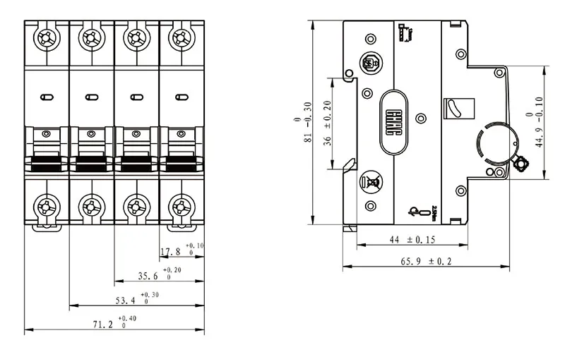
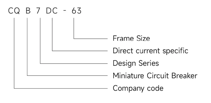
For product screening, the CHAC DC circuit-breaker range provides a category starting point, while the CQB7DC-63 series page is a model-family route for a more specific document request. These pages do not replace the project study or the exact product instructions.
The lowest purchase price is not necessarily the lowest project cost. Compare documentation completeness, fit with the approved connection, coordination evidence, substitution control and commissioning effort. An inexpensive device that triggers a redesign or cannot be traced to the approved diagram can cost more than the apparent unit saving.
Questions Buyers Ask About Solar DC Breakers
What type of DC breaker is needed for solar panels?
Use a breaker with published DC ratings that cover the circuit’s cold-temperature maximum voltage, continuous design current and prospective fault current, with the required polarity and pole arrangement. The exact type also depends on conductor protection, array architecture, grounding, installation conditions and required switching or isolation functions; confirm all of these against the product instructions and destination rules.
How do I calculate the correct size circuit breaker for solar panels?
First derive maximum PV voltage from the series string and the module’s temperature data at the project’s lowest design temperature. Then determine design current using the applicable PV design method, verify the conductor limit, evaluate reverse-current and fault contributions, and select a device whose published DC ratings and connection instructions cover every input. Do not apply a universal multiplier without the governing standard, code and source data.
How to calculate breaker size needed?
Record source type, maximum voltage, continuous design current, conductor allowable current, prospective fault current, load behavior, grounding, poles, polarity and environment. Choose the rating or setting only after all those constraints intersect; a current calculation by itself does not establish voltage suitability or breaking capacity.
What size circuit breaker for 400w solar panel?
A 400 W label is insufficient to select a breaker. Two 400 W modules can have different open-circuit voltage, short-circuit current and temperature behavior, and series or parallel connections change the circuit conditions. Obtain the module data sheet, string layout, minimum design temperature, conductor details and fault-current paths before sizing.
Does a DC breaker replace a PV disconnector, SPD or arc-fault device?
Not by default. Overcurrent protection, isolation, surge protection, residual-current or earth-fault protection and arc-fault detection are different functions. Treat each separately unless the exact product documentation explicitly declares and supports the combined function for the installation.
Sources for Solar DC Breaker Selection
- CEI, IEC 62548-1:2023+AMD1:2025 CSV—Photovoltaic (PV) arrays—Part 1: Design requirements.
- CEI, IEC 60364-7-712:2025—Low-voltage electrical installations—Part 7-712: Requirements for special installations or locations—Solar photovoltaic (PV) power supply installations.
- CEI, IEC 60947-2:2024—Low-voltage switchgear and controlgear—Part 2: Circuit-breakers.
The dependable rule is simple: approve the breaker from the documented circuit and connection, never from wattage or a familiar front-label number alone.
When your one-line, source data and fault-current review are ready, send the required ratings, pole and polarity arrangement, installation conditions and target-market documentation needs through CHAC Electric’s contact team for product matching and a document check.