Un RCD que se desconecta cuando se enciende un segundo circuito puede parecer defectuoso incluso cuando responde a un error en la instalación eléctrica. La sustitución del dispositivo no corrige un neutralizado robado, una conexión neutral-tierra en la derivación o una fuga acumulada excesiva. La pregunta práctica es si el Diagrama de cableado de RCD, Los conductores instalados y el equipo conectado describen la misma zona protegida. La agrupación incorrecta puede interrumpir cargas no relacionadas y hacer que el diagnóstico sea costoso; un tipo de corriente residual inadecuado también puede dejar una brecha de protección. Esta guía separa los defectos de diseño de los conductores de la selección del dispositivo y explica qué debe establecerse en un registro de inspección y prueba cualificado antes de que la instalación sea aceptada.
La respuesta breve es que la instalación segura de los RCD es una decisión de sistema. Encuentra cada conductor vivo del circuito protegido a través de una sola disposición de detección, separa los neutros posteriores y nunca utilices la tierra protectora como neutro. El IEC 60364-4-41 especifica la protección adicional de los RCD en contextos específicos, generalmente en un caudal residual de operación nominal no superior a 30 mA; esta no es una configuración universal ni un reemplazo para la conexión a tierra y la protección contra sobrecorriente. Confirma la función del dispositivo, la respuesta de la forma de onda, las instrucciones de instalación y las normas adoptadas localmente. Una persona cualificada debe verificar la función del circuito instalado; un simple funcionamiento del botón de prueba por sí solo no es suficiente.
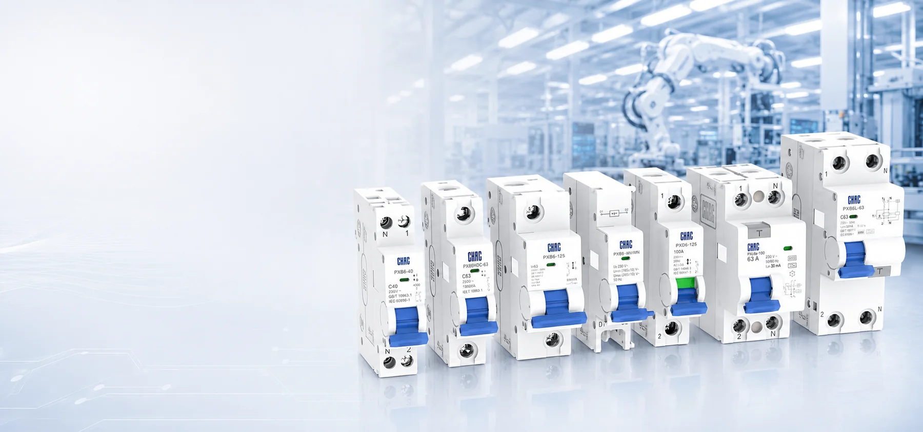
RCD es el término general para un dispositivo de corriente residual. Un RCCB proporciona protección residual sin protección integral contra sobrecorriente; un RCBO combina ambas funciones. Las etiquetas comerciales como “disyuntor diferencial” o “disyuntor contra fuga de tierra” en sí mismas no identifican la protección proporcionada. Lea la norma del producto, la función, los polos, la clasificación de la corriente, la característica de la corriente residual y las condiciones del sistema conjuntamente.
¿Cómo detecta un RCD la corriente de avería?
En una configuración común de transformador de corriente, todos los conductores activos pasan a través de un sensor de suma. Los flujos de salida y de entrada se cancelan normalmente; el flujo de salida por un camino no previsto genera una diferencia que puede activar el desconexionamiento dentro de unos umbrales y tiempos definidos. Por lo tanto, en un circuito monofásico, la línea y el neutro, o cada fase y el neutro asociado en un circuito multiphasico, deben compartir la disposición de detección especificada. La tierra protectora no es un retorno del circuito ni un neutro conmutado.
Un RCCB requiere una protección coordinada contra sobrecarga y cortocircuito; un RCBO integra esas funciones. Los módulos de corriente residual industriales y los sistemas de toroidales independientes son otras configuraciones, que no son sustitutos automáticos e intercambiables. Formas de presentación de los RCD distingue estas instalaciones y sus estándares. La sustitución puede cambiar la protección, el espacio de alojamiento, la mano de obra y el costo total de la placa.
| Marcaje RCD | Lo que identifica | Qué aún necesita verificación |
|---|---|---|
| RCD | Plazo de protección general contra la corriente residual | La categoría específica del dispositivo, las funciones y el estándar del producto. |
| Interruptor diferencial | Protección residual sin protección integral contra sobrecorriente | Protección contra sobrecarga y cortocircuito coordinada y las instrucciones del dispositivo. |
| Interruptor automático magnetotérmico modular con protección contra sobreintensidad y corriente de fuga a tierra | Protección contra la sobrecarga y la sobrecorriente | Ambas funciones, polos, clasificación de la resistencia del circuito y tipo de corriente residual. |
| Tipo AC | Respuesta residual de corriente alterna sinusoidal | Si la carga, las instrucciones y el código aplicable lo permiten. |
| Tipo A | Respuesta residual de corriente pulsante AC y DC definida | La forma de onda de la carga y las limitaciones relativas al DC continuo suave. |
| Tipo F | Respuesta de frecuencia compuesta especificada adicional | Las necesidades específicas de la carga controlada en frecuencia y del fabricante. |
| Tipo B | Definición de formas de onda de CC suaves y otras formas de onda de corriente residual | Instrucciones sobre el equipo, condiciones de suministro y coordinación requerida. |
Estas son dos preguntas de clasificación diferentes: la RCCB versus la RCBO identifica las funciones de protección, mientras que la AC/A/F/B identifica la respuesta de la forma de onda del corriente residual. Ninguna de estas clasificaciones especifica todos los aspectos relacionados con el tiempo de funcionamiento, la disposición de los polos ni la homologación. Las descripciones de la forma de onda se explican en el documento Schneider Electric’s Tipos de RCD, Actualizado el 5 de agosto de 2026.
¿Qué errores de cableado causan viajes no deseados o brechas de protección?
¿Por qué las marcas terminales deben guiar la instalación de un RCD?
Siga el diagrama de cableado del fabricante. Conecte los conductores de alimentación y de salida a los terminales de línea y carga identificados, a menos que el dispositivo haya sido declarado apto para otra orientación. La compatibilidad física no prueba la idoneidad; el circuito de prueba, la electrónica, la indicación y la coordinación pueden depender de la dirección.
Utilice todos los postes requeridos. Un dispositivo de cuatro postes en un circuito trifásico-plus-neutral normalmente monitorea todos los cuatro conductores de alimentación. Algunos productos también utilizan el neutro para la electrónica o el circuito de prueba. Siga los requisitos documentados de par, conductores, barras de distribución y carcasa, en lugar de copiar un dibujo genérico.
¿Cómo se diferencia una conexión neutra de tipo "neutro-a-tierra"?
Un neutro prestado conecta el conductor de línea de la carga con un grupo de RCD y su conductor de retorno con otro grupo o con un neutro aguas arriba. El corriente de retorno pasa por encima del sensor correcto. Las barras neutras aguas abajo interconectadas pueden tener el mismo efecto. El disparo puede producirse solo cuando una combinación particular de circuitos esté alimentada, por lo que reemplazar el RCD puede dejar el fallo sin cambios.
La conexión neutral-a-tierra en la parte inferior del sistema es diferente: une dos conductores que deben permanecer separados en esa parte de la instalación. Un cierto flujo de corriente de retorno puede fluir a través de la red de conductores protectores en lugar del neutral monitorizado. Ambos fallos pueden producir un desequilibrio residual, pero uno implica un recorrido incorrecto del neutral y el otro un camino de retorno paralelo no previsto. Un verificador cualificado debe determinar qué ruta existe, en lugar de considerar cada disparo como fallo de aislamiento o fuga de carga excesiva.
La configuración neutra/conectada a tierra permitida en la fuente no debe confundirse con una conexión en el extremo descendente. Definición de los sistemas de conexión a tierra estandarizados distingue los conductores neutros y protectores separados en el TN-S de los conductores combinados PEN en el TN-C. El esquema de puesta a tierra real determina el diseño; la tierra protectora debe permanecer continua y no debe ser reutilizada para evitar un corte de corriente. El rendimiento de la tierra-electrodo y la protección residual responden a preguntas distintas, como se explica en esta guía. resistencia de puesta a tierra de un edificio comercial explica.
| Causa posible | Distinción de trayectoria de corriente | Una investigación cualificada debería establecer |
|---|---|---|
| Neutrales prestados o interconectados | Return usa un valor neutral fuera del grupo protegido correcto. | La línea y la tierra de cada circuito pertenecen a la misma zona de detección a lo largo de las ramas. |
| Conexión neutral a tierra en el downstream | Return current can divide between monitored neutral and protective conductors. | Neutral/earth separation is correct for the supply arrangement and downstream location. |
| Cumulative leakage | Several correctly grouped loads contribute residual current. | The measured or declared standing leakage and switching behavior fit the selected grouping. |
How should leakage be managed when one RCD serves several circuits?
One RCD can protect several circuits where permitted, but leakage from filters, drives, power supplies, heaters, and long cables can accumulate. Circuit subdivision and the permitted standing-leakage allowance must follow the adopted wiring rules and device instructions; a design allowance is not a guaranteed trip point.
A leakage budget records declared or measured current for each load, includes cable and filter contributions, considers switching transients, and reserves appropriate margin for future additions. Missing data calls for measurement or reconsideration of circuit grouping. An unloaded check cannot establish behavior after the equipment is connected.
For business-critical boards, separate RCBOs or smaller RCD groups can improve continuity and diagnosis. Compare panel space, labor, test points, spare strategy, leakage, and the consequences of a common trip. Once the required functions are established, an Interruptor automático magnetotérmico modular con protección contra sobreintensidad y corriente de fuga a tierra product page can support a model-specific review, but the project needs the exact instructions and verified operating conditions.
How should RCD type, sensitivity, and timing be selected?
Additional protection using a device rated not above 30 mA is required in particular IEC 60364-4-41 applications and national implementations. It is not a universal value for every feeder, machine, earthing arrangement, or jurisdiction. Additional protection supplements basic and fault protection, protective earthing, bonding, insulation, enclosures, and correctly selected overcurrent devices. Where the functions are still being selected, compare the roles in this MCB vs RCBO selection guide.
Choose Type AC, A, F, or B after considering the load’s possible residual-current waveforms, supply system, manufacturer instructions, and code. Type A adds response to defined pulsating DC currents; Type F covers specified composite currents associated with certain single-phase frequency-controlled equipment; Type B extends coverage to defined smooth DC and other waveforms. Selection follows the expected fault signature, not a simple good-better-best ladder.
Accumulated leakage and DC residual current are different risks. AC leakage from several filters can add up and cause unwanted tripping, while smooth DC can impair an unsuitable device’s sensing response, often called blinding. Drives, EV chargers, UPS systems, and photovoltaic equipment require an equipment-specific assessment. “Electronic load” does not establish a universal RCD type, and the presence of solar generation does not by itself prove that every circuit requires Type B.
EV charging also illustrates why an equipment’s other protective functions matter. In Wallbox’s Commitment to EV Charging Standards, Wallbox explains Sweden’s May 2024 SEK Handbook 444 provisions and distinguishes Type B from arrangements using Type A or F with an IEC 62955 residual direct-current detecting device. Its named charger configurations are examples for that stated context, not a worldwide rule or evidence that a CHAC device includes DC detection. Keep the exact charger instructions and locally applicable requirements with the RCD selection record.
Where RCDs are in series, a coordinated, often time-delayed upstream device may let the unit nearest the fault operate first. Selectivity requires compatible operating-time bands, residual settings, device types, and manufacturer data; a larger upstream value alone proves nothing. A delay cannot replace the additional-protection performance required for a final circuit. Confirm that delay is permitted for the protective measure.
Surge-related unwanted tripping needs a separate review. Switching, filter capacitors, long cables, and lightning-related disturbances can produce transient residual currents despite acceptable standing leakage. Check documented disturbance immunity and the surge-protection arrangement rather than increasing the residual setting by guesswork.
Which standards govern the device and the installation?
IEC 60364-4-41 addresses protection against electric shock in low-voltage installations, including circumstances in which RCD additional protection is required. IEC 60364-6 addresses initial and periodic verification. These are installation standards, not product certificates or universal substitutes for national wiring rules. Countries can adopt them with modifications and additional requirements.
BS 7671 is the United Kingdom’s national wiring standard and is based substantially on the IEC 60364 series, with UK-specific provisions and amendments. A specification should cite the edition and amendment adopted for the project. Writing “IEC 60364/BS 7671 compliant” without a defined installation scope, design record, and verification evidence is too vague for procurement.
IEC 61008-1 covers RCCBs without integral overcurrent protection, while IEC 61009-1 covers RCBOs with integral overcurrent protection. IEC 62423 addresses Type F and Type B devices in its scope. Industrial assemblies can fall under IEC 60947-2 provisions, as described in Form factors of RCDs. The applicable product standard and evidence must match the exact device; a familiar form factor or printed type symbol is not sufficient evidence.
In the United States, NEC Article 210.8 addresses GFCI protection for specified locations and applications. GFCI and IEC-style RCD terminology overlap in purpose but are not interchangeable product categories, ratings, or approval paths. This overview of differential circuit breaker and GFCI terminology provides context; the adopted NEC edition, local amendments, listed equipment requirements, and authority having jurisdiction determine the actual installation requirements.
Unsupported standards or certification claims can lead to bid rejection, inspection delays, and redesign. The project record should identify the exact standard edition claimed, appropriate test or certification documentation, product markings, instructions, and traceability. Match evidence to the destination market, installation type, intended use, and claim being made.
What must qualified testing verify beyond the test button?
The test button exercises an internal test path and the release mechanism under the conditions specified by the manufacturer. It does not establish that every downstream neutral is correctly grouped or that protective-conductor continuity, insulation, polarity, or required disconnection performance has been verified. A working button therefore cannot clear a suspected borrowed-neutral or neutral-to-earth fault.
Begin with the single-line diagram and load inventory. Identify supply characteristics, earthing arrangement, live conductors, overcurrent protection, electronic loads, and continuity needs. Add a leakage budget and residual-waveform review before comparing one RCCB with coordinated breakers against separate RCBOs. For series devices, require documented selectivity rather than assuming that a delay or higher setting will coordinate them.
Before installation, confirm device category, poles, rated current, rated residual operating current, residual-current type, applicable standard, and required upstream protection. Retain the wiring diagram, line/load restrictions, neutral requirements, DC-leakage limitations, environmental limits, terminal data, and evidence for compliance claims.
| Stage | Question to close | Required evidence or action |
|---|---|---|
| Diseño | Which conductors and circuits are inside the protected zone? | Approved diagrams showing line, neutral, earth, and bonding arrangements. |
| Selection | What protection functions does the device provide? | Exact product standard, functions, poles, current rating, residual setting, and type. |
| Load review | Which residual-current waveforms and normal leakage may occur? | Equipment data, DC-leakage review, leakage budget, and grouping decision. |
| Coordinación | Will the intended device operate first? | Manufacturer residual-current and time data, overcurrent coordination, and any permitted delay. |
| Instalación | Are the protected conductors correctly routed? | Qualified inspection, neutral-group identification, terminal checks, and required torque records. |
| Verification | Does the installed protective measure perform as required? | Inspection, test-button operation, instrument tests, and documented results under the adopted verification rules. |
| Documentación | Can the installation and product claims be substantiated? | Instructions, applicable reports or certificates, traceability, and destination-market review. |
Qualified personnel should follow the authorized isolation and safe-work procedure. Continuity and insulation testing require appropriate de-energized conditions, while some functional RCD tests require an energized supply under controlled conditions. Do not describe all commissioning tests as tests on a dead circuit. Use suitable instruments and procedures, document the results, and follow the exact device instructions and local law.
How can an RCD test record help the next fault investigation?
Keep Cableado de RCD test results tied to the circuit configuration that was actually verified. A useful handover record identifies the device, protected circuits and neutral bar, the approved drawing revision, the test method and the result under that procedure. Without that connection, a later “passed” entry may refer to a circuit grouping that no longer exists.
Record subsequent circuit additions or neutral-bar changes beside the original result. If unwanted trips begin after an alteration, compare the before-and-after circuit grouping before assuming the device is defective. This document comparison helps a qualified investigator choose the next checks; it does not replace inspection or justify working on energized equipment.
Usa el RCCB installation and acceptance guide when the installed device has no integral overcurrent protection. The device identity matters because an RCCB test record should not silently stand in for evidence about a different RCBO or protective arrangement.
What are the frequently asked questions about RCD wiring?
How should an RCD be wired?
Connect it according to the manufacturer’s line/load diagram, routing every live conductor of the protected circuit through the specified sensing arrangement. Keep downstream neutrals in their correct groups, keep protective earth outside the normal load-current path, and have a qualified person inspect and test the completed installation.
Does an RCD test button work?
Yes, it should operate the device through its internal test circuit when the supply and connections meet the manufacturer’s requirements. This does not prove protective-conductor continuity, correct downstream neutral routing, insulation condition, or the required measured operating performance. A non-operating button needs qualified investigation; a working button does not replace installation verification.
Where is RCD protection required?
Requirements depend on the adopted installation code, circuit, location, intended use, and earthing system. IEC 60364-4-41 includes additional-protection requirements in particular contexts, while NEC 210.8 identifies specified GFCI applications in the United States. Check the locally adopted edition and amendments rather than transferring one jurisdiction’s rule to another.
What safety rules apply when RCD wiring is tested?
Qualified personnel must follow the site’s authorized isolation, prevention-of-reconnection, and absence-of-voltage verification procedures before work that requires a de-energized circuit. Functional tests requiring an energized supply need their own controlled test procedure. Account for all supply sources and follow local legal requirements and the equipment instructions.
Does an RCD need a neutral connection?
It depends on the circuit and device. A line-to-neutral protected circuit routes its neutral through the sensing arrangement, and some electronics or test circuits require a neutral connection. A circuit without neutral needs a device explicitly suitable for that arrangement; protective earth must never substitute for neutral.
Can an RCD trip from a neutral-to-earth fault when a circuit is switched off?
It can if only the line is disconnected and the circuit’s neutral remains connected: an unintended neutral-to-earth path can still divert return current from other loads in the protected group. The result depends on the actual switching and conductor arrangement, so an off switch does not prove the fault is isolated. A qualified person must distinguish that path from a borrowed neutral and ordinary leakage.
Do solar inverters and EV chargers always require a Type B RCD?
No universal requirement follows from those equipment names alone. The residual-current waveform, exact equipment instructions, built-in detection and disconnection functions, and locally adopted rules determine the arrangement. An EV-specific Type A or F plus RDC-DD provision must not be assumed to apply to a solar inverter or to equipment without documented DC detection.
Which references support these distinctions?
- Schneider Electric Electrical Installation Guide, Tipos de RCD, updated 5 August 2026: waveform-response distinctions, not model-specific approval.
- Schneider Electric Electrical Installation Guide, Formas de presentación de los RCD, updated 5 August 2026: device assemblies and associated product-standard scope.
- Schneider Electric Electrical Installation Guide, Definición de los sistemas de conexión a tierra estandarizados, updated 5 August 2026: IEC-context neutral, protective-conductor, and PEN distinctions.
- Wallbox, Wallbox’s Commitment to EV Charging Standards: manufacturer explanation of the May 2024 Swedish requirements and named charger arrangements. It does not establish a universal EV or photovoltaic rule.
What should determine the final wiring decision?
Residual-current protection works only when device capability, conductor routing, coordination, and verification agree. First identify the supply and earthing arrangement, then define each protected circuit and its neutral path. Select protective functions and waveform response separately, using equipment data rather than a generic diagram. Finally, check the assembled installation and retain the results; neither a replacement device nor a successful test-button operation resolves an unexplained return-current path. For projects evaluating an integrated solution, the residual current circuit breaker with overcurrent protection product page provides a starting point for review with CHAC Eléctrico. Confirm exact model documentation, application suitability, and destination-market requirements before specification.