Un pedido de un “contactor NC” puede tener dos significados muy diferentes: un contactor con un contacto auxiliar normalmente cerrado, o un dispositivo cuyos contactos de potencia están normalmente cerrados. Confundirlos puede provocar un comportamiento de control incorrecto o someter un pequeño contacto auxiliar a una corriente para la cual nunca fue diseñado. Por lo tanto, la disposición de los contactos debe leerse en el diagrama técnico correspondiente y no inferirse a partir de la fotografía del producto. Esta guía explica el estado normal, separa las funciones de potencia y de control, y muestra cómo especificar la configuración de los contactos, la bobina y las clasificaciones sin hacer suposiciones infundadas sobre funciones de interbloqueo o de seguridad.
Un Contactor de NC La descripción requiere aclaración. NC significa normalmente cerrado: en un dispositivo electromagnético convencional sin retención, el contacto indicado está cerrado en la condición normal de desenergizado y se abre al ser accionado. La descripción podría referirse únicamente a un contacto auxiliar, mientras que los polos principales permanecen normalmente abiertos. Confirme el diagrama real de contactos, el número de polos, la categoría de utilización y la alimentación de la bobina. Ni las siglas NC ni un contacto cerrado en reposo garantizan una función de seguridad, un estado de fallo seguro ni la idoneidad para conducir la corriente del motor.
¿Cuál es el estado normal de un contacto NC?
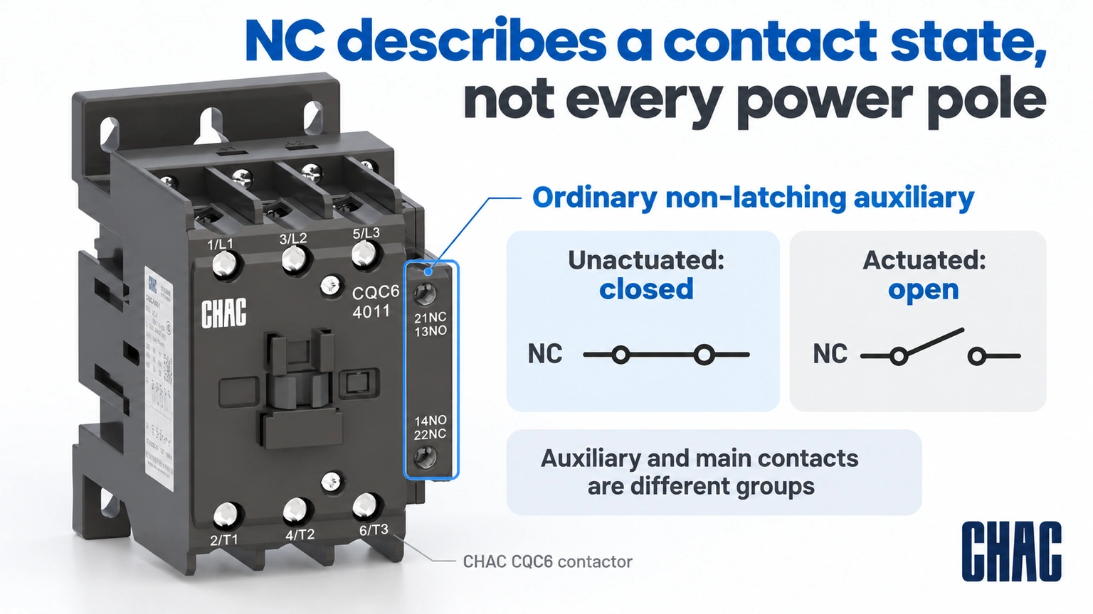
En un contactor ordinario sin retención, el estado normal se refiere a la condición no accionada y desenergizada que se muestra en la documentación del dispositivo. Un contacto normalmente abierto está abierto en ese estado; un contacto normalmente cerrado está cerrado. Cuando el mecanismo se activa, sus estados cambian según el diseño específico.
No extienda esta descripción simplificada a todos los dispositivos de conmutación con bloqueo, de retención mecánica o especializados. El estado mecánico almacenado o un mecanismo de operación diferente pueden modificar la forma en que debe interpretarse el esquema. Utilice el diagrama y la descripción de funcionamiento del fabricante en lugar de asumir que la pérdida de alimentación de la bobina siempre devuelve cada dispositivo a la misma condición.
| Contact description | Ordinary unactuated state | What remains to be checked |
|---|---|---|
| Normally open auxiliary | Abierto | Control rating and intended circuit |
| Normally closed auxiliary | Cerrado | Control rating and intended circuit |
| Main power contact | As shown in the exact diagram | Power duty, voltage and current |
| Latching or specialized device | Defined by its mechanism and documentation | Reset behavior and stored state |
Does one NC auxiliary contact make the power circuit normally closed?
No. Main contacts switch the specified load; auxiliary contacts serve control, indication or interlocking functions within their ratings. A three-pole normally open power contactor can include a normally closed auxiliary. Calling the entire product NC without naming the contact group loses this distinction.
La empresa Schneider Electric FAQ FA112430, modified May 12, 2026, identifies 13–14 as normally open and 21–22 as normally closed auxiliary terminals on the stated TeSys D contactors. This is a traceable product-family example, not permission to infer the terminal arrangement of an unrelated device. Verify the marking and diagram on the selected model.
Why do auxiliary-contact ratings differ from main-contact ratings?
The contact groups perform different duties. A motor contactor may have an AC-3 power rating, while its auxiliary contacts carry separate control-circuit ratings. The relevant current also depends on operational voltage and whether the control load is AC or DC. A thermal-current figure is not an automatic switching rating for an inductive control load.
Para normally closed contacts, this matters when switching a coil, an indicator or an input circuit. Very small electronic-input loads also need the contact’s minimum-load suitability checked. Choosing the contact solely because its printed current exceeds the steady-state load can miss both switching duty and low-level reliability requirements.
How are NC contacts used in interlocking and feedback?
An NC auxiliary can be part of an electrical interlock that prevents one contactor from being commanded while another is actuated. It can also provide a status signal interpreted by a controller. The actual circuit and failure analysis determine what that signal means; an ordinary auxiliary state is not proof that every main pole is open.
Where the design requires mechanical interlocking, mirror contacts, mechanically linked contacts or a safety-rated function, obtain the exact supporting documentation. A normal NC designation does not establish those properties. Similarly, a feedback signal should not be labeled “safe” merely because it changes state when coil power is removed.
| Proposed function | Relevant check | What NC alone does not prove |
|---|---|---|
| Electrical interlock | Actual sequence and compatible contact arrangement | Mechanical prevention of simultaneous closure |
| Controller feedback | Signal rating and interpretation | All power poles are positively open |
| Control-coil switching | AC/DC duty and contact rating | Motor-load switching capacity |
| Safety function | Required certified components and system design | A guaranteed safe state after any failure |
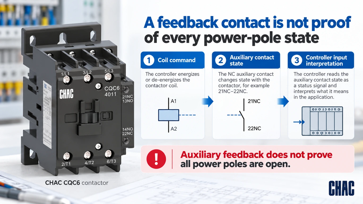
Why should the coil command, auxiliary state and controller input be checked separately?
They describe three different things: what the controller requests, what the contact mechanism does and what the input circuit reports. For a healthy ordinary non-latching NC auxiliary, the expected unactuated contact is closed and the actuated contact is open, as defined by its diagram. The PLC’s displayed zero or one also depends on its input wiring and logic; NC does not automatically mean a displayed zero.
Put those expected states beside the control drawing before the approved functional check. If the command changes but the reported state does not, investigate the actual coil supply, contact configuration, wiring and input interpretation rather than immediately declaring the main poles welded. The auxiliary’s behavior alone cannot establish the condition of every power contact. This separation is particularly useful after replacing a block or changing a controller program without changing the contactor body.
How should a buyer specify the contact configuration?
State the main power-pole arrangement separately from the auxiliary NO/NC count. Then specify operational voltage, utilization category, current, coil supply and the exact accessories. Schneider’s utilization-category guide, DOCA0189EN-05, shows why a contactor’s load duty is part of its selection. Its coordination guidance also makes clear that short-circuit behavior belongs to a documented combination, not to the NC label.
CHAC CQC6 auxiliary contact options include published F4 combinations such as F4-11 with 1NO + 1NC, F4-20 with 2NO and F4-02 with 2NC. These accessory descriptions do not convert the main poles into NC power contacts. Confirm the accessory’s compatibility and its own control ratings before ordering.
For related industrial switching requirements, review the CQC1 AC contactor family against its own model data. Do not infer an NC power variant from the availability of an auxiliary block in another series. The normally open versus normally closed contactor guide provides a related explanation of the operating-state distinction.
What should be rechecked when a suppression module or auxiliary block changes?
Review the expected transition as well as the final state. Coil suppression can affect how quickly stored energy decays after the control signal is removed. Durakool’s Nota técnica sobre la supresión de bobinas explains the release-time trade-off. Its relay examples do not supply a release-time specification for a CHAC contactor.
Use the exact contactor, accessory and control-output instructions to define the permitted behavior. Under an approved commissioning procedure, check the command sequence, contact feedback and any required interlock response. Do not invent a universal delay or increase a software timeout simply to hide unexplained feedback. Keep the accepted component references and control-program revision with the result. A final NC continuity check cannot establish that a timed interlock or safety-related sequence has been validated.
What should be checked before an NC contact is replaced?
Record the original diagram, accessory code and circuit function before removing the device. With the system properly isolated and stored energy addressed, qualified personnel can compare the contact behavior with the specified states and inspect for damage. A continuity check alone does not establish the contact’s permitted switching duty or overall service condition.
The replacement auxiliary contact block must preserve the intended logic as well as the mechanical fit. Check coil suppression and control timing where they affect the sequence. Investigate unexpected behavior rather than rewiring around an interlock or treating an NC contact as a universal substitute for a relay.
What do buyers ask about NC contactors?
What is a NC contactor?
It is an ambiguous shorthand that may mean a contactor with an NC auxiliary contact or a device with NC power contacts. Specify which contact group is meant and verify the actual diagram.
What is the difference between a NC contactor and a NO contactor?
NC and NO describe the stated contact’s normal unactuated condition. The main and auxiliary contacts may have different arrangements, so the complete device cannot always be described by one label.
What is a NO NC contactor switch?
The expression usually refers to a switching device or contact set with normally open and normally closed functions. Confirm the exact product, contact diagram and ratings rather than relying on the phrase.
What is the difference between NC and NO contacts?
For an ordinary non-latching device, an NC contact is closed at rest and an NO contact is open at rest. Actuation changes their states according to the device design.
What does nc contactor do in a control circuit?
An NC auxiliary may be used for interlocking, indication or control within its rating. Its presence does not prove a safety function or that the main power poles are normally closed.
How is nc contactor different from a relay?
NC describes a contact state that can appear in either product. Select a relay or contactor by its actual load duty, ratings, coil, configuration and required approvals.
Referencias
- Schneider Electric FA112430: TeSys D NO/NC auxiliary-terminal identification; modified May 12, 2026
- Schneider Electric DOCA0189EN-05: contactor utilization categories; accessed October 19, 2026
- Schneider Electric FA105974: short-circuit coordination; modified April 20, 2026
- Durakool: A Layman’s Guide to Coil Suppression; accessed October 19, 2026. Relay examples explain the mechanism, not CHAC contactor timing.
Conclusión
The useful distinction is between the state of a particular contact and the function of the complete switching device. Define whether NC refers to an auxiliary or a power contact, then verify the diagram, control or power duty, coil supply and compatible accessories. An NC contact can support an interlock or feedback circuit without establishing a certified safety function or proving that every main pole is open. Preserve the intended logic when replacing parts, and do not infer contact ratings from another group on the same device. CHAC publishes CQC6 auxiliary configurations and model-specific contactor information for this review. Using those records alongside the actual circuit drawing gives buyers a precise configuration to confirm instead of an ambiguous request for an NC contactor.