
Calculadora de tamaño de cable — Cobre/PVC
Dimensionar cables de cobre/PVC en mm² utilizando la capacidad de corriente corregida y la caída de tensión resistiva. Abarca tres conductores cargados en el aire según los métodos A1, A2, B1, B2 y C.
Localice el conductor de cobre/PVC de menor sección nominal que cumpla con las verificaciones de capacidad de carga y de caída de tensión por resistencia, para un circuito trifásico equilibrado.
Resultado
Referencia del conductor de cobre/PVC
6.00mm²Solo comprobaciones de la tabla y de caída de resistencia6 mm² es el conductor más pequeño que cumple con los límites de capacidad de corriente y caída de tensión resistiva ingresados.
Iz = Itable × ktemperature × kother; Ib ≤ In ≤ Iz; ΔV% = 100 × √3 × I × ρ70 × L / (S × V)Figura seleccionada G20, hileras de cobre/PVC que cubren tres conductores cargados a 30°C de aire de referencia, método A1/A2/B1/B2/C. La caída utiliza cobre resistivo a 70°C y excluye la reactancia. Verifique por separado la corriente de funcionamiento convencional del dispositivo de protección, la capacidad de soportar cortocircuitos, los terminales y la carga de neutro/armónicos.
¿Por qué este resultado?
Corregido Iz ≥ 32.00 A; caída de tensión ≤ 3%. Método C, ambiente 30°C, corrección total 1.000. Cobre/PVC, tres conductores cargados; resistencia a 70°C.
Referencia seleccionada y opciones adyacentes enumeradas. Los valores se redondean para su visualización; las comprobaciones utilizan valores sin redondear.
| Tamaño del cable | Capacidad corregida | Disminución de la tensión | Motivo |
|---|---|---|---|
| 4 mm² | 32.00 A · Cumple el requisito | 3.63% · Por encima del límite | Caída de tensión por encima del límite |
| 6 mm²Referencia seleccionada | 41.00 A · Cumple el requisito | 2.42% · Dentro del límite | Primer partido registrado para estos controles |
| 10 mm² | 57.00 A · Cumple el requisito | 1.45% · Dentro del límite | Se cumplieron los requisitos; opción incluida más tarde |
Ver todas las opciones verificadas de 16
| Tamaño del cable | Capacidad corregida | Disminución de la tensión | Motivo |
|---|---|---|---|
| 1.5 mm² | 17.50 A · Requisito siguiente | 9.67% · Por encima del límite | Capacidad corregida por debajo de In; Caída de tensión por encima del límite |
| 2.5 mm² | 24.00 A · Requisito siguiente | 5.80% · Por encima del límite | Capacidad corregida por debajo de In; Caída de tensión por encima del límite |
| 4 mm² | 32.00 A · Cumple el requisito | 3.63% · Por encima del límite | Caída de tensión por encima del límite |
| 6 mm²Referencia seleccionada | 41.00 A · Cumple el requisito | 2.42% · Dentro del límite | Primer partido registrado para estos controles |
| 10 mm² | 57.00 A · Cumple el requisito | 1.45% · Dentro del límite | Se cumplieron los requisitos; opción incluida más tarde |
| 16 mm² | 76.00 A · Cumple el requisito | 0.91% · Dentro del límite | Se cumplieron los requisitos; opción incluida más tarde |
| 25 mm² | 96.00 A · Cumple el requisito | 0.58% · Dentro del límite | Se cumplieron los requisitos; opción incluida más tarde |
| 35 mm² | 119.00 A · Cumple el requisito | 0.41% · Dentro del límite | Se cumplieron los requisitos; opción incluida más tarde |
| 50 mm² | 144.00 A · Cumple el requisito | 0.29% · Dentro del límite | Se cumplieron los requisitos; opción incluida más tarde |
| 70 mm² | 184.00 A · Cumple el requisito | 0.21% · Dentro del límite | Se cumplieron los requisitos; opción incluida más tarde |
| 95 mm² | 223.00 A · Cumple el requisito | 0.15% · Dentro del límite | Se cumplieron los requisitos; opción incluida más tarde |
| 120 mm² | 259.00 A · Cumple el requisito | 0.12% · Dentro del límite | Se cumplieron los requisitos; opción incluida más tarde |
| 150 mm² | 299.00 A · Cumple el requisito | 0.10% · Dentro del límite | Se cumplieron los requisitos; opción incluida más tarde |
| 185 mm² | 341.00 A · Cumple el requisito | 0.08% · Dentro del límite | Se cumplieron los requisitos; opción incluida más tarde |
| 240 mm² | 403.00 A · Cumple el requisito | 0.06% · Dentro del límite | Se cumplieron los requisitos; opción incluida más tarde |
| 300 mm² | 464.00 A · Cumple el requisito | 0.05% · Dentro del límite | Se cumplieron los requisitos; opción incluida más tarde |
Aún por confirmar
- Verifique por separado la capacidad de soportar cortocircuitos, la corriente de operación del dispositivo de protección, los terminales y la carga en el neutro y las armónicas.
- Esta estimación de la resistencia excluye la reactancia del cable; la tabla de cargas no abarca otras configuraciones de conductores ni métodos de instalación.
Fuente de datos: Guía de instalación eléctrica — Figura G20 referencia cobre/PVC (abre en una nueva pestaña)
Fórmula y método
Dimensionar cables de cobre/PVC en mm² utilizando la capacidad de corriente corregida y la caída de tensión resistiva. Abarca tres conductores cargados en el aire según los métodos A1, A2, B1, B2 y C.
Cómo utilizar esta calculadora
- Confirme que esta tabla es aplicable: cobre, PVC, tres conductores cargados y uno de los métodos de instalación en aire enumerados.
- Introduzca la corriente de carga, la corriente del dispositivo de protección, la longitud de la ruta, la temperatura ambiente y un factor de corrección adicional justificado.
- Revise el área más pequeña enumerada que cumpla tanto con las verificaciones de corriente como de caída de tensión, luego verifique la capacidad de soportar fallas y todas las condiciones de instalación restantes.
Limitaciones de cálculo
No se extrapola a CC, dos conductores cargados, aluminio, XLPE, cable enterrado ni circuitos paralelos. La tabla de 1.5–300 mm² con carga es un subconjunto de referencia. La reactancia de CA, los armónicos, el dispositivo I2 ≤ 1.45 Iz y el cumplimiento total del código requieren verificaciones separadas.
Cálculo del dimensionamiento de cables: capacidad de carga y caída de tensión
La referencia cargada es la Figura G20 de la Guía de Instalación Eléctrica: conductores de cobre, aislamiento de PVC, tres conductores cargados y un límite del conductor de 70°C. Esta versión incluye los métodos de instalación en aire A1, A2, B1, B2 y C. Comprueba tanto la capacidad corregida como un límite de caída de tensión resistiva ingresado.
Notas de entrada
| Entrada | Qué comprobar |
|---|---|
| Clasificación actual y de los dispositivos de protección | La verificación de la entrada requiere que Ib ≤ In. A continuación, la búsqueda exige que la corriente admisible corregida Iz del cable seleccionado sea al menos igual a In. |
| Instalación y corrección | Elija el método indicado en la lista. El factor de temperatura del aire se aplica internamente; el producto de corrección adicional debe excluir ese mismo factor de temperatura. |
| Temperatura del cable y del conductor | La estimación de la caída de tensión utiliza la resistividad del cobre corregida desde 20°C hasta 70°C. Excluye la reactancia del cable y no modela armónicos ni cargas de fases desiguales. |
Ejemplo práctico · valores iniciales de la forma
32 Un circuito, cobre/PVC fijado directamente
Tres conductores cargados · método C · 30°C aire · otro factor 1.00 · 400 V · un sentido 50 m · límite de caída 3%
4 mm² tiene una capacidad base de 32 A pero supera el límite de caída de resistencia del 3% ingresado.
6 mm² has 41 A base/corrected capacity and approximately 2.42% resistive drop.
6.00 mm²
6 mm² is the first loaded row meeting both entered bounds. The cable still needs fault-withstand, terminal, neutral/harmonic and protective-device operating-current checks.
Cálculo del dimensionamiento de cables: capacidad de carga y caída de tensión
Cable ampacity is the current a conductor can carry under stated installation and temperature conditions. Start with circuit design current Ib and protective-device rating In. Select a conductor whose corrected current capacity Iz is at least In, with Ib ≤ In.
Then check the route length against the chosen voltage-drop limit. The smallest cable that carries the current may still lose too much voltage on a long run. In the default example, 4 mm² meets 32 A base capacity in method C but fails the entered drop limit; 6 mm² is the first listed size meeting both checks.
A wire size calculator must use the right installation table
This version returns metric copper conductor areas for PVC insulation and three loaded conductors. It uses the stated air-installation methods A1, A2, B1, B2 and C, with a 70°C conductor limit. Select the actual installation method before comparing the table’s current values.
Corrected capacity equals the base table value multiplied by the air-temperature factor and your additional correction product. Grouping or other applicable factors can reduce capacity further. Do not include the air-temperature factor again in the extra field; it is already applied by the calculator.
Cable size and circuit breaker rating must be checked together
Increasing a breaker rating without checking the cable can remove the intended overload protection. Recheck corrected ampacity whenever device rating, route conditions or grouping changes. Also verify protective-device operating-current requirements and cable short-circuit withstand.
The voltage-drop result here is a resistive estimate using copper resistance at 70°C. Cable reactance, harmonic currents and neutral loading require additional assessment. The table does not cover AWG, aluminium, XLPE, buried cables, DC circuits or parallel conductors; those need their own verified sizing data.
Keep the table conditions attached to the result
- Do not apply these three-loaded-conductor PVC rows to DC, two-loaded-conductor circuits, XLPE, aluminium, buried cable or parallel conductors. Those require the appropriate separate tables and corrections.
- Ib ≤ In ≤ Iz is one part of conductor protection. Verify the applicable conventional operating-current condition, short-circuit withstand, disconnection conditions and voltage drop using the complete installation data.
Preguntas frecuentes
Why does this version only support copper/PVC and three loaded conductors?
Those are the verified table conditions loaded into the calculator. Other constructions require different source data and must not be inferred from these values.
Why can a cable pass ampacity but fail the tool?
A long route can exceed the chosen voltage-drop limit even when corrected current capacity is sufficient. Both checks must be met.
Should I include ambient temperature in the extra correction product?
No. The selected temperature factor is already applied. Use the extra field for justified additional factors such as grouping, without counting the same effect twice.
Does this verify the neutral conductor and short-circuit withstand?
No. These require separate checks, particularly where harmonics load the neutral or the protective device limits fault energy.
Does this wire size calculator return AWG sizes?
No. It selects from the loaded metric copper/PVC table in mm². Converting area to an approximate AWG designation does not transfer the table’s ampacity to a different cable construction or installation standard.
Can I increase the circuit breaker size when voltage drop is too high?
A larger breaker does not reduce cable resistance or voltage drop. Review conductor area, length and installation conditions, then check the protective device against the selected cable’s corrected current capacity.
¿Necesita ayuda para elegir un producto CHAC?
Envíe el voltaje del sistema, la corriente de carga y las condiciones de instalación con su consulta.
Copper/PVC cable current-carrying capacity
Base ampacity values from Electrical Installation Guide, Figure G20. This is an external installation reference, not a CHAC cable product rating.
Reference data. Calculate to highlight the matching row.
Scroll horizontally on small screens to read all columns.
| Conductor area (mm²) | A1 (A) | A2 (A) | B1 (A) | B2 (A) | C (A) |
|---|---|---|---|---|---|
| 1.5Current reference | 13.5 | 13 | 15.5 | 15 | 17.5 |
| 2.5Current reference | 18 | 17.5 | 21 | 20 | 24 |
| 4Current reference | 24 | 23 | 28 | 27 | 32 |
| 6Current reference | 31 | 29 | 36 | 34 | 41 |
| 10Current reference | 42 | 39 | 50 | 46 | 57 |
| 16Current reference | 56 | 52 | 68 | 62 | 76 |
| 25Current reference | 73 | 68 | 89 | 80 | 96 |
| 35Current reference | 89 | 83 | 110 | 99 | 119 |
| 50Current reference | 108 | 99 | 134 | 118 | 144 |
| 70Current reference | 136 | 125 | 171 | 149 | 184 |
| 95Current reference | 164 | 150 | 207 | 179 | 223 |
| 120Current reference | 188 | 172 | 239 | 206 | 259 |
| 150Current reference | 216 | 196 | 262 | 225 | 299 |
| 185Current reference | 245 | 223 | 296 | 255 | 341 |
| 240Current reference | 286 | 261 | 346 | 297 | 403 |
| 300Current reference | 328 | 298 | 394 | 339 | 464 |
- A1
- Insulated conductors in conduit in a thermally insulated wall.
- A2
- Multicore cable in conduit in a thermally insulated wall.
- B1
- Insulated conductors in conduit on a wall.
- B2
- Multicore cable in conduit on a wall.
- C
- Cable sujeto directamente o sobre una bandeja sin perforaciones, dentro de las condiciones del método de origen.
Leyendo esta referencia
- Conductores de cobre, aislamiento de PVC, tres conductores cargados, límite del conductor de 70°C y aire ambiente de 30°C. Solo se reproducen los métodos A1, A2, B1, B2 y C.
- Los valores numéricos de esta tabla de referencia permanecen como valores base. La calculadora aplica la temperatura y otros factores de corrección ingresados por separado.
- No aplique estos valores al aluminio, al XLPE, a los circuitos de corriente continua, a dos conductores cargados, a cables enterrados ni a conductores paralelos. Verifique las condiciones completas de la instalación en la fuente.
Fuente: Electrical Installation Guide — Figure G20 and installation methods (abre en una nueva pestaña)
Source checked: . This is the retrieval date, not a standard edition or product revision date.
Ejemplo de aplicación · Datos ilustrativos
Checking a warm equipment feeder for ampacity and drop
For a 40 A load and 40 A protective-device reference, consider an 80 m, 400 V three-phase copper/PVC route using method B2, 40°C ambient and an entered grouping factor of 0.80. The calculator returns 16 mm²: its 62 A base capacity becomes 43.15 A after correction, and the resistive voltage drop is 1.81%, below the example’s 3% target. The cable values are installation-reference data, not CHAC cable ratings. When reviewing PXB6-63 or CQM6 protection, also check the actual route, fault withstand and trip behavior; passing voltage drop alone does not establish cable suitability.
Datos del producto: Disyuntor miniatura PXB6-63 · Fabricante OEM de disyuntores moldeados (MCCB) estándar CQM6
Productos relacionados de CHAC
Compare the protective-device ratings with the cable’s corrected current-carrying capacity.
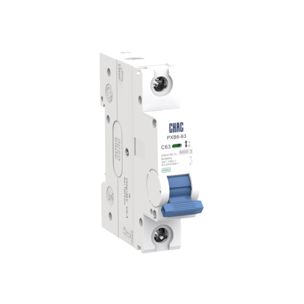
PXB6-63
Disyuntor miniatura
Verifique la corriente nominal, el número de polos y la curva de disparo.
Ver el producto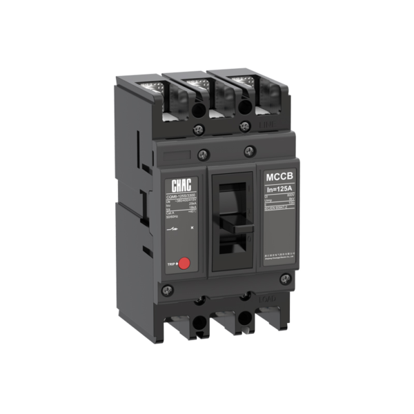
CQM6
Disjuntor de carcasa moldeada
Revisen el bastidor, la unidad de disparo y la capacidad de ruptura.
Ver el producto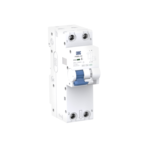
PXB6L-63
Residual current circuit breaker with overcurrent protection
Check residual-current type, sensitivity and overcurrent ratings.
Ver el producto