
Kalkulator średnicy przewodu — miedź/PVC
Rozmiar kabli miedzianych/PVC w mm² z uwzględnieniem skorygowanej przenoszenia prądu i spadku napięcia rezystancyjnego. Obejmuje trzy obciążone przewody metodami A1, A2, B1, B2 oraz C.
Znajdź najmniejszy wymieniony przewód miedziany z izolacją PVC, który spełnia wprowadzone wymagania dotyczące dopuszczalnego prądu oraz spadku napięcia rezystancyjnego w przypadku symetrycznego obwodu trójfazowego.
Wynik
Referencja przewodnika miedzianego/PVC
6.00mm²Tylko sprawdzenie tablicy i spadku napięcia na rezystorze6 mm² jest najmniejszym wymienionym przewodem, który spełnia wprowadzone limity prądowej wytrzymałości i spadku napięcia rezystancyjnego.
Iz = Itable × ktemperature × kother; Ib ≤ In ≤ Iz; ΔV% = 100 × √3 × I × ρ70 × L / (S × V)Wybrany rysunek G20 miedź/PVC przedstawia trzy obciążone przewody przy temperaturze powietrza referencyjnego 30°C, metoda A1/A2/B1/B2/C. Spadek napięcia uwzględnia rezystancję miedzi przy temperaturze 70°C i nie obejmuje reaktancji. Sprawdź oddzielnie prąd znamionowy urządzenia zabezpieczającego, wytrzymałość na zwarciowe obciążenie prądowe, zaciski oraz obciążenie neutralnym/harmoniczami.
Dlaczego ten wynik?
Skorygowana Iz ≥ 32.00 A; spadek napięcia ≤ 3%. Metoda C, otoczenie 30°C, całkowita korekcja 1.000. Miedź/PVC, trzy obciążone przewody; rezystancja przy 70°C.
Wybrane opcje referencyjne i sąsiednie, wpisane w listę. Wartości są zaokrąglone do wyświetlania; weryfikacje wykorzystują wartości niezaokrąglone.
| Rozmiar kabla | Skorygowana pojemność | Spadek napięcia | Powód |
|---|---|---|---|
| 4 mm² | 32.00 A · Spełnia wymagania | 3.63% · Powyżej limitu | Spadek napięcia przekracza limit |
| 6 mm²Wybrany odnośnik | 41.00 A · Spełnia wymagania | 2.42% · W granicach normy | Pierwszy zapisany mecz dla tych sprawdzeń |
| 10 mm² | 57.00 A · Spełnia wymagania | 1.45% · W granicach normy | Czeki zrealizowane; opcja dodana później |
Wyświetl wszystkie zaznaczone opcje 16
| Rozmiar kabla | Skorygowana pojemność | Spadek napięcia | Powód |
|---|---|---|---|
| 1.5 mm² | 17.50 A · Poniższy wymóg | 9.67% · Powyżej limitu | Corrected capacity below In; Voltage drop above limit |
| 2.5 mm² | 24.00 A · Below requirement | 5.80% · Above limit | Corrected capacity below In; Voltage drop above limit |
| 4 mm² | 32.00 A · Spełnia wymagania | 3.63% · Powyżej limitu | Spadek napięcia przekracza limit |
| 6 mm²Wybrany odnośnik | 41.00 A · Spełnia wymagania | 2.42% · W granicach normy | Pierwszy zapisany mecz dla tych sprawdzeń |
| 10 mm² | 57.00 A · Spełnia wymagania | 1.45% · W granicach normy | Czeki zrealizowane; opcja dodana później |
| 16 mm² | 76.00 A · Meets requirement | 0.91% · Within limit | Czeki zrealizowane; opcja dodana później |
| 25 mm² | 96.00 A · Meets requirement | 0.58% · Within limit | Czeki zrealizowane; opcja dodana później |
| 35 mm² | 119.00 A · Meets requirement | 0.41% · Within limit | Czeki zrealizowane; opcja dodana później |
| 50 mm² | 144.00 A · Meets requirement | 0.29% · Within limit | Czeki zrealizowane; opcja dodana później |
| 70 mm² | 184.00 A · Meets requirement | 0.21% · Within limit | Czeki zrealizowane; opcja dodana później |
| 95 mm² | 223.00 A · Meets requirement | 0.15% · Within limit | Czeki zrealizowane; opcja dodana później |
| 120 mm² | 259.00 A · Meets requirement | 0.12% · Within limit | Czeki zrealizowane; opcja dodana później |
| 150 mm² | 299.00 A · Meets requirement | 0.10% · Within limit | Czeki zrealizowane; opcja dodana później |
| 185 mm² | 341.00 A · Meets requirement | 0.08% · Within limit | Czeki zrealizowane; opcja dodana później |
| 240 mm² | 403.00 A · Meets requirement | 0.06% · Within limit | Czeki zrealizowane; opcja dodana później |
| 300 mm² | 464.00 A · Meets requirement | 0.05% · Within limit | Czeki zrealizowane; opcja dodana później |
Jeszcze do potwierdzenia
- Verify short-circuit withstand, protective-device operating current, terminals and neutral/harmonic loading separately.
- This resistive estimate excludes cable reactance; the loaded table does not cover other conductor constructions or installation methods.
Źródło danych: Electrical Installation Guide — Figure G20 copper/PVC reference (otwiera się w nowej karcie)
Formuła i metoda
Rozmiar kabli miedzianych/PVC w mm² z uwzględnieniem skorygowanej przenoszenia prądu i spadku napięcia rezystancyjnego. Obejmuje trzy obciążone przewody metodami A1, A2, B1, B2 oraz C.
Jak używać tego kalkulatora
- Confirm this table applies: copper, PVC, three loaded conductors and one of the listed air installation methods.
- Enter load current, protective-device current, route length, ambient temperature and a justified additional correction product.
- Review the smallest listed area meeting both current and resistive-drop checks, then verify fault withstand and all remaining installation conditions.
Granice obliczeniowe
Does not extrapolate to DC, two loaded conductors, aluminium, XLPE, buried cable or parallel circuits. The loaded 1.5–300 mm² table is a reference subset. AC reactance, harmonics, device I2 ≤ 1.45 Iz and full code compliance require separate checks.
Cable sizing calculation: ampacity and voltage drop
The loaded reference is Figure G20 of the Electrical Installation Guide: copper conductors, PVC insulation, three loaded conductors and a 70°C conductor limit. This version includes air-installation methods A1, A2, B1, B2 and C. It checks both corrected capacity and an entered resistive voltage-drop limit.
Notatki wprowadzane
| Wprowadzenie | Czego należy się zorientować |
|---|---|
| Current and protective-device rating | The input check requires Ib ≤ In. The search then requires the selected cable’s corrected Iz to be at least In. |
| Installation and correction | Choose the actual listed method. The air-temperature factor is applied internally; the additional correction product must exclude that same temperature factor. |
| Drop and conductor temperature | The voltage-drop estimate uses copper resistivity corrected from 20°C to 70°C. It excludes cable reactance and does not model harmonics or unequal phase loads. |
Przykładowe rozwiązanie · wartości początkowe
32 A circuit, copper/PVC clipped direct
Three loaded conductors · method C · 30°C air · other factor 1.00 · 400 V · one-way 50 m · drop limit 3%
4 mm² has 32 A base capacity but exceeds the entered 3% resistive-drop limit.
6 mm² has 41 A base/corrected capacity and approximately 2.42% resistive drop.
6.00 mm²
6 mm² is the first loaded row meeting both entered bounds. The cable still needs fault-withstand, terminal, neutral/harmonic and protective-device operating-current checks.
Cable sizing calculation: ampacity and voltage drop
Cable ampacity is the current a conductor can carry under stated installation and temperature conditions. Start with circuit design current Ib and protective-device rating In. Select a conductor whose corrected current capacity Iz is at least In, with Ib ≤ In.
Then check the route length against the chosen voltage-drop limit. The smallest cable that carries the current may still lose too much voltage on a long run. In the default example, 4 mm² meets 32 A base capacity in method C but fails the entered drop limit; 6 mm² is the first listed size meeting both checks.
A wire size calculator must use the right installation table
This version returns metric copper conductor areas for PVC insulation and three loaded conductors. It uses the stated air-installation methods A1, A2, B1, B2 and C, with a 70°C conductor limit. Select the actual installation method before comparing the table’s current values.
Corrected capacity equals the base table value multiplied by the air-temperature factor and your additional correction product. Grouping or other applicable factors can reduce capacity further. Do not include the air-temperature factor again in the extra field; it is already applied by the calculator.
Cable size and circuit breaker rating must be checked together
Increasing a breaker rating without checking the cable can remove the intended overload protection. Recheck corrected ampacity whenever device rating, route conditions or grouping changes. Also verify protective-device operating-current requirements and cable short-circuit withstand.
The voltage-drop result here is a resistive estimate using copper resistance at 70°C. Cable reactance, harmonic currents and neutral loading require additional assessment. The table does not cover AWG, aluminium, XLPE, buried cables, DC circuits or parallel conductors; those need their own verified sizing data.
Keep the table conditions attached to the result
- Do not apply these three-loaded-conductor PVC rows to DC, two-loaded-conductor circuits, XLPE, aluminium, buried cable or parallel conductors. Those require the appropriate separate tables and corrections.
- Ib ≤ In ≤ Iz is one part of conductor protection. Verify the applicable conventional operating-current condition, short-circuit withstand, disconnection conditions and voltage drop using the complete installation data.
Często zadawane pytania
Why does this version only support copper/PVC and three loaded conductors?
Those are the verified table conditions loaded into the calculator. Other constructions require different source data and must not be inferred from these values.
Why can a cable pass ampacity but fail the tool?
A long route can exceed the chosen voltage-drop limit even when corrected current capacity is sufficient. Both checks must be met.
Should I include ambient temperature in the extra correction product?
No. The selected temperature factor is already applied. Use the extra field for justified additional factors such as grouping, without counting the same effect twice.
Does this verify the neutral conductor and short-circuit withstand?
No. These require separate checks, particularly where harmonics load the neutral or the protective device limits fault energy.
Does this wire size calculator return AWG sizes?
No. It selects from the loaded metric copper/PVC table in mm². Converting area to an approximate AWG designation does not transfer the table’s ampacity to a different cable construction or installation standard.
Can I increase the circuit breaker size when voltage drop is too high?
A larger breaker does not reduce cable resistance or voltage drop. Review conductor area, length and installation conditions, then check the protective device against the selected cable’s corrected current capacity.
Potrzebujesz pomocy przy wyborze produktu CHAC?
W swoim zapytaniu należy podać napięcie zasilania, prąd obciążenia oraz warunki montażu.
Copper/PVC cable current-carrying capacity
Base ampacity values from Electrical Installation Guide, Figure G20. This is an external installation reference, not a CHAC cable product rating.
Reference data. Calculate to highlight the matching row.
Scroll horizontally on small screens to read all columns.
| Conductor area (mm²) | A1 (A) | A2 (A) | B1 (A) | B2 (A) | C (A) |
|---|---|---|---|---|---|
| 1.5Current reference | 13.5 | 13 | 15.5 | 15 | 17.5 |
| 2.5Current reference | 18 | 17.5 | 21 | 20 | 24 |
| 4Current reference | 24 | 23 | 28 | 27 | 32 |
| 6Current reference | 31 | 29 | 36 | 34 | 41 |
| 10Current reference | 42 | 39 | 50 | 46 | 57 |
| 16Current reference | 56 | 52 | 68 | 62 | 76 |
| 25Current reference | 73 | 68 | 89 | 80 | 96 |
| 35Current reference | 89 | 83 | 110 | 99 | 119 |
| 50Current reference | 108 | 99 | 134 | 118 | 144 |
| 70Current reference | 136 | 125 | 171 | 149 | 184 |
| 95Current reference | 164 | 150 | 207 | 179 | 223 |
| 120Current reference | 188 | 172 | 239 | 206 | 259 |
| 150Current reference | 216 | 196 | 262 | 225 | 299 |
| 185Current reference | 245 | 223 | 296 | 255 | 341 |
| 240Current reference | 286 | 261 | 346 | 297 | 403 |
| 300Current reference | 328 | 298 | 394 | 339 | 464 |
- A1
- Insulated conductors in conduit in a thermally insulated wall.
- A2
- Multicore cable in conduit in a thermally insulated wall.
- B1
- Insulated conductors in conduit on a wall.
- B2
- Multicore cable in conduit on a wall.
- C
- Cable clipped direct or on an unperforated tray, within the source method conditions.
Reading this reference
- Copper conductors, PVC insulation, three loaded conductors, 70°C conductor limit and 30°C ambient air. Only methods A1, A2, B1, B2 and C are reproduced.
- The numbers in this reference table remain the base values. The calculator applies temperature and other entered correction factors separately.
- Do not apply these values to aluminium, XLPE, DC circuits, two loaded conductors, buried cables or parallel conductors. Verify the complete installation conditions in the source.
Source: Electrical Installation Guide — Figure G20 and installation methods (otwiera się w nowej karcie)
Source checked: . This is the retrieval date, not a standard edition or product revision date.
Przykład zastosowania · Wykresowe dane wejściowe
Checking a warm equipment feeder for ampacity and drop
For a 40 A load and 40 A protective-device reference, consider an 80 m, 400 V three-phase copper/PVC route using method B2, 40°C ambient and an entered grouping factor of 0.80. The calculator returns 16 mm²: its 62 A base capacity becomes 43.15 A after correction, and the resistive voltage drop is 1.81%, below the example’s 3% target. The cable values are installation-reference data, not CHAC cable ratings. When reviewing PXB6-63 or CQM6 protection, also check the actual route, fault withstand and trip behavior; passing voltage drop alone does not establish cable suitability.
Dane produktu: PXB6-63 Zmniejszona moc rozruchowa · CQM6 Standardowy złącze obrotowe w obudowie (MCCB) Producent OEM
Powiązane produkty CHAC
Compare the protective-device ratings with the cable’s corrected current-carrying capacity.
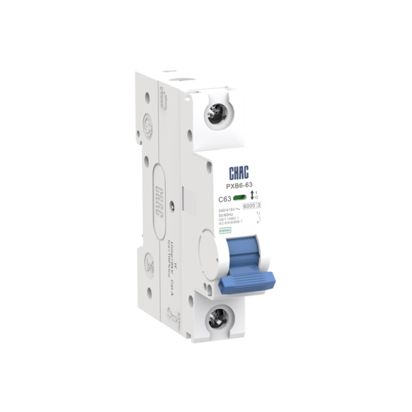
PXB6-63
Miniaturowy wyłącznik automatyczny
Sprawdź prąd znamionowy, liczba biegunów i krzywą uruchamiania.
Zobacz produkt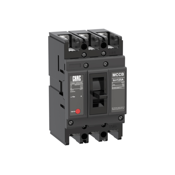
CQM6
Przełącznik obwodowy w obudowie formowanej
Przeglądaj ramę, jednostkę przemieszczania i jej wytrzymałość na zerwanie.
Zobacz produkt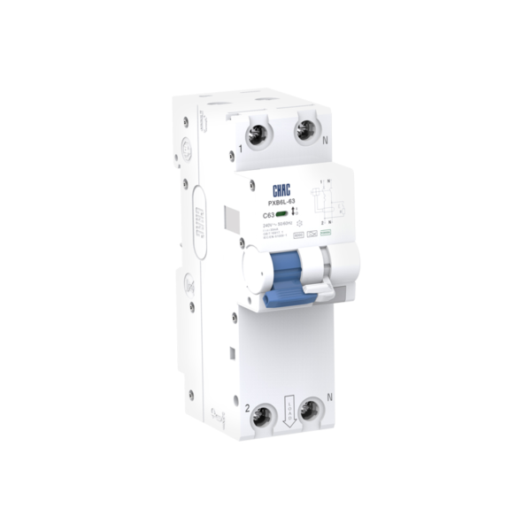
PXB6L-63
Residual current circuit breaker with overcurrent protection
Check residual-current type, sensitivity and overcurrent ratings.
Zobacz produkt