A commercial-building ground test can produce a low reading without answering the question that matters at handover: does the installation meet its approved protection and grounding design? Electrode resistance, protective-conductor continuity and fault-loop impedance describe different parts of that decision. Confusing them can lead to unnecessary excavation or leave a defective bonding connection unaddressed. The acceptance process should establish what was measured, how the electrode was connected during the test and which code or project requirement controls the result.
The short answer is that no single ground-resistance limit applies to every commercial building. NEC 250.53(A)(2) connects 25 ohms to a specific provision for a single rod, pipe or plate electrode; it is not a universal safety threshold. A specification calling for 5 ohms also needs its own design or contractual basis rather than being presented as a general building-code requirement. Define the electrode, supply arrangement, test method, connected state, seasonal conditions, governing code and acceptance authority before deciding whether a result passes.
That distinction matters because buyers often ask for the maximum resistance recommended for commercial building electrical installation as if a single value settled the issue. Electrode resistance describes how an electrode system couples to earth under stated conditions. It does not prove that a breaker will clear a fault, that exposed metal is bonded, or that touch voltage stays within a safe design limit.
A stronger commissioning package connects design intent, installed geometry, soil conditions, test evidence, and a repeatable baseline. This approach helps the owner correct the hazard that actually controls risk instead of spending money to chase an isolated reading.
What does a ground-resistance reading actually measure?
Grounding-electrode resistance is the opposition between an electrode system and the surrounding earth, expressed in ohms. The value includes the electrode-to-soil interface and the resistance of the soil volume carrying test current. Electrode depth and spacing, soil layers, moisture, temperature, corrosion, nearby buried metal, and unintended parallel conductors can all influence the result.
Soil resistivity is related but different. It is a property of the soil volume, normally expressed in ohm-metres and investigated with a four-pin Wenner test at several probe spacings. Resistivity data helps an engineer choose electrode depth, grid geometry, spacing, and material. It cannot replace an installed-system test after excavation, backfill, foundations, drainage, and buried services have changed the site.
The following checks answer different questions and should not be collapsed into one grounding result.
| Measurement or check | What it evaluates | Primary decision | What it cannot prove by itself |
|---|---|---|---|
| Grounding-electrode resistance | Electrode system to earth | Whether earth coupling meets the approved design and test basis | That the metallic fault-return path is continuous or low impedance |
| Protective-conductor continuity | Equipment grounding or protective conductors | Whether a continuous conductive path exists | How effectively the electrode transfers current into soil |
| Fault-loop impedance | Source-to-fault-and-return loop | Whether the protective device can disconnect under required conditions | Electrode performance as a standalone value |
| Equipotential bonding verification | Connections between exposed and extraneous conductive parts | Whether required bonds are present and continuous | That a remote soil test point has low resistance or all touch voltages are acceptable |
| Insulation resistance | Insulation between conductors and earth or other conductors | Whether insulation is damaged or contaminated | Continuity of bonds or electrode condition |
System grounding also needs its own definition. It establishes how a current-carrying conductor or source is referenced to earth; equipment grounding provides a fault-current path; equipotential bonding connects accessible conductive parts as required by the design. An excellent electrode reading cannot compensate for a missing bonding jumper or undersized equipment grounding conductor. The acceptance plan should therefore coordinate the earth test with grounding and protective-device testing appropriate to the supply arrangement.
When does the 25-ohm rule apply?
NEC 250.53(A)(2) is frequently quoted beyond its scope. In commonly adopted editions of NFPA 70 National Electrical Code, a single rod, pipe, or plate electrode must be supplemented by an additional permitted electrode unless the single electrode is demonstrated to have a resistance to earth of 25 ohms or less. Check the actual adopted edition and clause, not just the standard’s catalogue page. Local amendments, construction documents, and the authority having jurisdiction (AHJ) control each project.
The rule does not establish 25 ohms as the maximum for every grounding-electrode system, nor does a result below 25 ohms prove personnel safety. Concrete-encased electrodes, ground rings, structural steel, engineered grids, and complete grounding-electrode systems are not evaluated by turning the single-electrode provision into a general pass/fail rule.
Substation grounding, for example, is evaluated around tolerable touch and step voltages using fault current, clearing time, surface layer, soil model, and grid geometry under IEEE Std 80 Guide for Safety in AC Substation Grounding. That scope should not be converted into a blanket commercial-building resistance limit. Sensitive commercial operations may also impose owner or utility criteria that go beyond the minimum installation code.
The project specification should state the design function and acceptance path. If it calls for a resistance target, it should also identify the electrode system, method, isolation or connected state, test season, and party authorized to accept deviations. Without those details, two competent technicians can produce different values because they measured different configurations.
How does the supply arrangement change the verification plan?
For IEC-context projects, first establish whether the installation uses TT, TN or IT earthing. Schneider Electric’s Definition of standardised earthing schemes, edited 5 August 2026, describes TT as a supply source with an earthed point and installation conductive parts connected to a separate earth electrode. In TN-S, protective and neutral conductors are separate; in TN-C, one PEN conductor combines those functions. These are circuit arrangements, not resistance grades.
This distinction changes what the survey must identify before testing: the source reference, protective-conductor route, neutral arrangement and installation electrode connections. A building labelled TT and one labelled TN-S should not receive an identical acceptance checklist merely because both contain earth electrodes. The cited definitions do not establish a universal electrode target or the required disconnection time; those must come from the applicable national adoption and protection design.
The same guide warns against using TN-C downstream of TN-S in a TN-C-S arrangement because interruption of the upstream neutral would also interrupt the downstream protective conductor. Treat an unclear PEN or neutral/protective connection as a design-verification issue, not something to disconnect experimentally to obtain a cleaner resistance value. IEC scheme terminology also does not replace the adopted US requirements on a US project.
How does the test method change the reading?
What does a fall-of-potential test establish?
The three-point fall-of-potential test injects current between the electrode under test and a remote current probe. A potential probe measures voltage at several locations between them, allowing the tester to plot resistance against probe position. A stable region in the curve is stronger evidence than a single convenient point because it helps assess whether the probe arrangement has separated the relevant resistance areas.
Simple single-position shortcuts should not be treated as universal procedures. Large grids, multiple electrodes, layered soil, limited test distance, and overlapping resistance areas can shift or eliminate the stable portion of the curve. Use the applicable procedure in IEEE Std 81 Guide for Measuring Earth Resistivity Ground Impedance and Earth Surface Potentials of a Grounding System, together with the instrument instructions and approved site test plan. Confirm the specified edition before testing; a catalogue entry alone is not the complete procedure.
What must be checked before an electrode is isolated?
Isolating an electrode may interrupt a protective connection or expose hazardous voltage. Long probe leads also need controlled routes that avoid traffic and buried-service conflicts. A disconnecting device is only one part of safe grounding-test isolation; the work plan must identify the connections being opened, affected protection and the conditions for restoring service.
For US workplaces within its scope, OSHA’s 1910.333 Selection and use of work practices requires safe deenergizing procedures to be determined beforehand, disconnection from all electric energy sources, and applicable lockout/tagging. A qualified person must verify the deenergized condition, including possible induced voltage or unrelated backfeed. Push buttons and interlocks are not acceptable as the sole means of deenergizing.
The test plan should therefore account for alternate supplies and backfeed before deciding that an open main switch makes disconnection safe. If the intended isolation cannot be safely achieved, the engineer and qualified testing team must select another approved method or arrange the necessary outage. A desire to measure an individual electrode does not justify removing a protective connection from an operating installation.
When are clamp-on and selective methods appropriate?
A clamp-on ground tester induces a signal around a conductor and measures the resistance of the complete loop. The method therefore needs a parallel return path through other bonded electrodes or conductive connections. It is useful for checks and trending in a suitable multi-grounded system, but the usual loop method cannot measure an isolated single electrode that has no return loop.
The displayed value depends on the electrode branch encircled, the other return paths and any metallic connections that alter the loop. It is not automatically the standalone resistance of the entire grounding system. Before accepting the number, draw the measurement loop and identify what the clamp actually encircles; a lower value after a bonding change may describe a different circuit rather than an improved electrode.
A selective method combines injected test current with a clamp around the conductor under assessment, reducing the need for full disconnection in suitable configurations. It still requires a valid injected-current circuit, accessible conductors and compliance with the tester’s procedure; interference or circulating current can affect results. Fall-of-potential, selective, and clamp-on values answer related but not interchangeable questions. Document a change of method instead of hiding it in the trend record.
How do weather and soil conditions affect results?
Soil moisture and temperature can move the reading even when the electrode has not changed. Rain or a high water table often lowers resistance; drought, drainage work, frozen soil, or dry backfill can raise it. Chemical treatment is not an automatic remedy: its suitability, corrosion implications and environmental acceptability require project-specific review.
Commission near the season or soil condition that presents the design concern, or define an approved seasonal allowance. Record recent rainfall, soil surface condition, temperature, connected configuration, and any construction changes. A result taken after heavy rain should not be compared uncritically with one collected in dry or frozen conditions.
What should be checked when a comparable reading changes?
A defensible commercial building ground resistance program holds the method and test point as consistent as practicable. A single reading contains the electrode condition, test setup, soil state and instrument uncertainty; it can identify a problem without establishing its cause.
| Observed change | First checks | Do not assume |
|---|---|---|
| Sudden lower value | Clamp loop, new parallel bond, utility connection and probe placement | That the electrode suddenly became better. |
| Sudden higher value | Loose or corroded connection, lost parallel path, dry soil, excavation or damaged conductor | That adding chemicals is the correct remedy. |
| Different result after changing method | Fall-of-potential curve, clamp return path, isolation state and instrument setup | That two methods produce interchangeable numbers. |
| Movement after construction | Drainage, landscaping, buried services, test-well condition and as-built drawings | That the old baseline still represents the installed geometry. |
Install accessible test links or wells where the design permits, give each point a unique identifier, and show it on the as-built drawing. A useful grounding test record includes the instrument model and calibration status, lead route, probe distances, raw values, calculated result, connected state, weather, and tester. Retain the fall-of-potential curve rather than only the selected number; for clamp-on tests, retain the conductor location and a sketch or photograph of the return loop.
Trend direction under comparable conditions, not merely the difference from a round-number target. A sustained rise may indicate corrosion, a damaged conductor, loose connection, altered drainage, excavation, or a lost parallel path. A sudden drop can also deserve investigation because a new buried service or unintended bond may have changed the test circuit. Confirm the setup before repairing the electrode system.
Maintainability should be a design input. Accessible bonds, test points, durable labels and complete records allow later investigations without repeatedly excavating finished surfaces or guessing which connection was tested.
How should a commercial building’s acceptance target be set?
Start with the function and consequence of failure. An office building, data center, lightning-exposed facility, industrial plant, and substation do not share one controlling risk. The engineer should reconcile local code, utility rules, protective-device studies, lightning and telecommunications interfaces, soil data, owner requirements, and maintenance access.
| Application | Primary risk | Basis for the target | Acceptance evidence |
|---|---|---|---|
| Office or retail building | Fault clearing and bonding defects | Adopted code, electrode type, supply arrangement, and engineer or AHJ criteria | Identified electrodes plus earth tests, continuity checks, and loop or disconnection verification as applicable |
| Data center or communications facility | Availability, surge paths, and multiple bonded systems | Electrical safety coordinated with owner, IT, telecom, and surge-protection requirements | Bonding topology, seasonal baseline, approved test points, and change records |
| Lightning-exposed commercial site | Impulse-current distribution and dangerous potential differences | Coordinated electrical and lightning-protection design | Down-conductor interfaces, equipotential bonds, inspections, and defined earth-test method |
| Industrial facility | Fault duty, process downtime, and corrosive conditions | Protection study, environment, materials, and maintenance plan | Material and joint condition, fault-duty inputs, corrosion controls, and repeatable field records |
| Substation or site grid | Touch and step voltage during a ground fault | Engineered analysis using fault current, clearing time, soil model, surface layer, and grid geometry | IEEE 80 design basis with IEEE 81 field data, drawings, calculations, and commissioning results |
Life-cycle cost includes electrodes, trenching, exothermic or mechanical connections, corrosion control, test wells, surface restoration, outage access, and periodic retesting. An unnecessarily aggressive resistance target can add civil work without reducing the controlling hazard. Conversely, an installation that omits access and records shifts expense into future investigations.
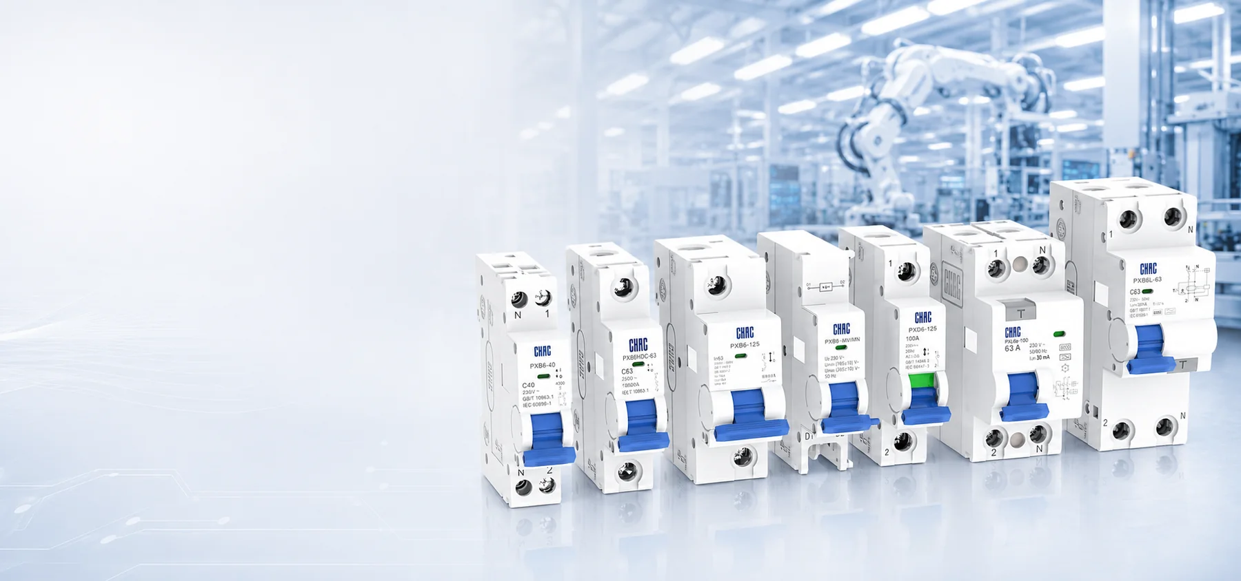
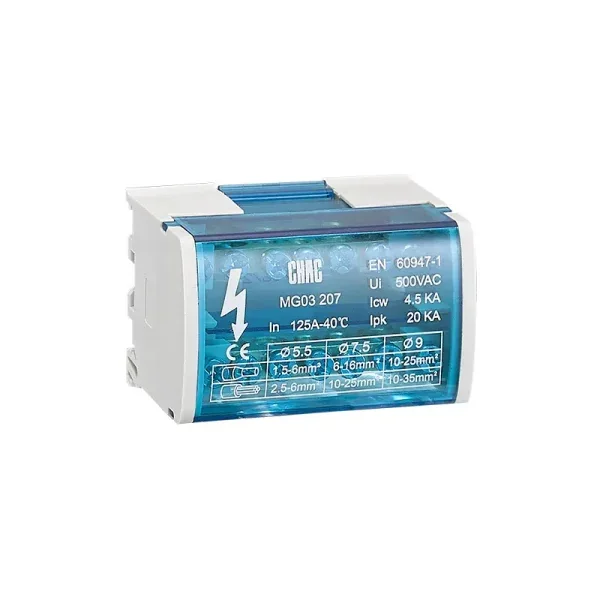
Procurement documents should separate product requirements from site acceptance. The enclosure and board package may include commercial electrical distribution equipment such as the CQMG20C Series distribution box, but equipment selection still depends on voltage, fault level, protective coordination, enclosure rating, conductors, and local compliance. No distribution product replaces an engineered grounding design or field test.
Which standards and records support acceptance?
NFPA 70 governs electrical installation where adopted in the United States, subject to local amendments and the applicable edition. IEEE 81 is a measurement guide for earth resistivity, ground impedance, and earth-surface potentials; it is not a product certification. IEEE 80 focuses on safety in AC substation grounding and should not be reduced to a generic resistance target.
For IEC projects, IEC 60364-6 Low-voltage Electrical Installations Part 6 Verification addresses initial and periodic verification of low-voltage installations. Verification extends beyond electrode resistance to inspection and the tests applicable to the installation, including protective-conductor continuity, insulation resistance and automatic-disconnection conditions. Confirm the adopted edition and national requirements when preparing the checklist.
The final record should identify the governing edition, drawings, electrode geometry, connected state, method, instrument and calibration status, raw readings, environmental conditions, assumptions, acceptance criterion, deviations, and approving party. A meter screenshot or supplier brochure cannot replace the required engineering or AHJ disposition.
What else do facilities teams ask about commercial building grounding?
Is ground resistance above 25 ohms acceptable?
It can be acceptable when the governing code pathway, electrode type, system design, and engineer or AHJ criteria permit it. For a single NEC rod, pipe, or plate electrode, a value above 25 ohms commonly triggers the supplemental-electrode provision rather than proving that the entire building is unsafe. Confirm the adopted clause and any stricter project target.
What is the maximum allowable grounding resistance for a commercial building?
There is no universal maximum for every commercial installation. The approved value must come from the adopted code, electrode arrangement, system function, utility or owner requirements, risk study, and project specification. Neither 25 ohms nor 5 ohms should be imposed without that context.
How is grounding resistance tested in a commercial building?
Common methods include three-point fall-of-potential, selective, and clamp-on testing. The correct choice depends on electrode geometry, available probe distance, safe isolation, and the measurement circuit. Record the connected state so a later result can be meaningfully compared.
Can a clamp meter test one isolated ground rod?
Not with the usual clamp-on loop method if the rod has no parallel return path. The tester needs a complete loop, so an isolated electrode typically requires fall-of-potential or another method approved for the site configuration.
How often should a commercial grounding system be tested?
Set the interval through local requirements, facility criticality, corrosion exposure, soil variability, the maintenance plan, and previous trends. Consider retesting after significant excavation, lightning or fault events, utility changes, or unexplained movement in comparable readings; the need and scope should be determined for the affected installation.
Is a lower reading always safer?
Not by itself. Confirm the method, bonding state, fault-clearing path, touch/step-voltage design where applicable, and project acceptance basis. A changed clamp loop or connected configuration can lower the displayed value without improving the electrode under assessment.
What belongs in a grounding test record?
Include the electrode identifier, drawing reference, method, probe distances or clamp loop, instrument and calibration status, raw readings, weather and soil condition, connected state, selected result, deviations, and approval. If a method or connection changes, start a clearly identified new baseline rather than treating the reading as directly comparable.
Does opening the main disconnect make electrode disconnection safe?
Not automatically. The plan must consider all energy sources, induced voltage, backfeed and the protective function of the conductor to be opened. Within OSHA 1910.333’s US workplace scope, qualified-person verification and applicable lockout/tagging are required before exposed parts are treated as deenergized.
Which references should the acceptance team consult?
- NFPA 70 National Electrical Code, Article 250 in the edition adopted by the jurisdiction; consult the actual section for the electrode arrangement.
- IEEE Std 81 Guide for Measuring Earth Resistivity Ground Impedance and Earth Surface Potentials of a Grounding System, in the project-specified edition.
- IEEE Std 80 Guide for Safety in AC Substation Grounding, for its substation design scope.
- IEC 60364-6 Low-voltage Electrical Installations Part 6 Verification, with the applicable national adoption.
- Schneider Electric, Definition of standardised earthing schemes, edited 5 August 2026; guidance on IEC-context circuit arrangements, not universal resistance targets.
- US OSHA, 1910.333 Selection and use of work practices; US occupational electrical-work requirements, not a global installation code.
The most useful resistance value is the one tied to a known electrode, valid method, credible conditions, and accountable acceptance decision. First establish the supply arrangement and governing criteria; then coordinate electrode testing with continuity and protective-device verification; finally retain enough detail to repeat the test. A convenient low number is not a substitute for that sequence, and obtaining an isolated-electrode result must never override the safety plan. When a project moves from grounding design to board selection, review CHAC’s electrical panel planning guide et équipement de distribution électrique. Confirm the destination-market requirements and specific equipment documentation separately from the site’s grounding acceptance.