A panel buyer orders a connector marked 1/2 inch for an enclosure opening measured at roughly 22 mm. The labels initially appear inconsistent, so the order is delayed while someone searches for a smaller opening. This illustrative mix-up comes from comparing a conduit trade designation with a physical hole diameter.
Ringkasan: Electrical knockout dimensions are not the same as conduit trade sizes. A common 1/2-inch trade-size entry is approximately 7/8 inch, or 22.2 mm, across. Use the fitting manufacturer’s required opening and permitted panel thickness as the final selection criteria; a nominal chart is a starting point, not a fabrication tolerance.
Why conduit trade size differs from the actual knockout diameter
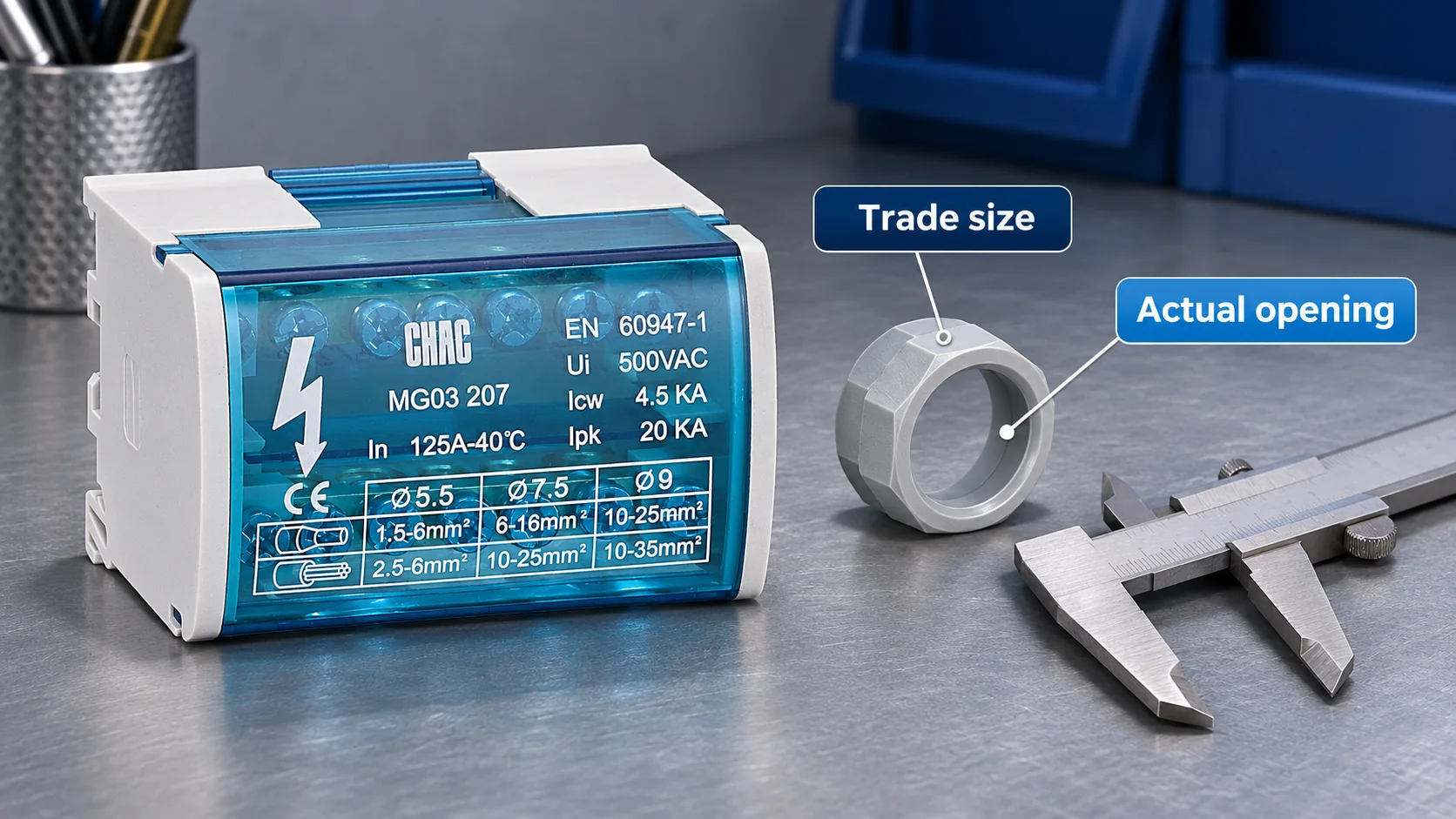
A conduit trade size is a standardized naming convention. It does not directly state the conduit’s outside diameter, the connector thread’s outside diameter or the required hole in the enclosure wall. Those dimensions serve different purposes and must be compared using their own specifications.
Knockout punches can also use different naming conventions. A conduit-size punch is labeled for the intended trade-size fitting, while a dimensional punch is labeled by the hole size it produces. A tool marked 3/4 inch under one convention therefore should not be assumed to make the same hole as one marked 3/4 inch under the other.
| Common conduit trade designation | Nominal opening reference | Approximate metric equivalent |
|---|---|---|
| 1/2 inch | 7/8 inch | 22.2 mm |
| 3/4 inch | 1-1/8 inches | 28.6 mm |
| 1 inch | 1-3/8 inches | 34.9 mm |
| 1-1/4 inches | 1-3/4 inches | 44.5 mm |
| 1-1/2 inches | 2 inches | 50.8 mm |
| 2 inches | 2-1/2 inches | 63.5 mm |
These are common nominal reference sizes for familiar conduit-entry applications. Actual punch cutting diameters, connector instructions and enclosure specifications may differ slightly. Do not use the rounded metric column as an instruction to drill a precision hole or as proof that a metric cable gland will fit.
For example, an M20 gland and a 1/2-inch conduit connector belong to different dimensional systems. A similar-looking mounting end does not establish interchangeability. Check the specified clearance hole, thread form, sealing surface and locknut rather than comparing names or approximate diameters alone.
How to check whether a connector fits an existing knockout
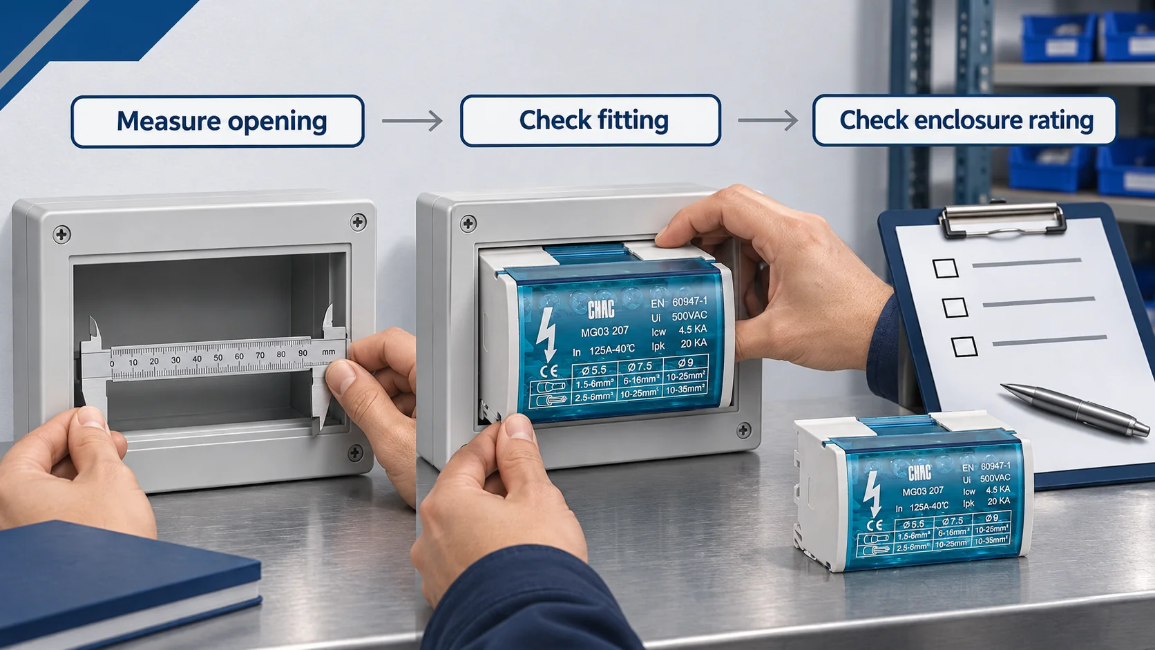
Measure the clear opening in more than one direction after confirming the equipment is safe to work on. An irregular or damaged edge can produce misleading readings. Record the measured range, wall thickness and any remaining concentric rings, then compare those observations with the connector’s installation instructions.
The connector must pass through the opening while allowing its shoulder, sealing washer and locknut to seat correctly where applicable. Adequate thread engagement matters. A fitting that can be pushed through a hole is not necessarily suitable for the panel thickness or able to maintain the required enclosure protection.
Also check internal clearance. The body of a connector, its locknut and the required cable bend can interfere with terminals, barriers or neighboring fittings. A hole that is correctly sized but poorly located can still force an enclosure redesign. Include these clearances in the entry schedule before releasing a drawing for manufacture.
| Periksa | Record or obtain | Alasan |
|---|---|---|
| Opening | Measured diameter, shape and edge condition | Confirm the actual hole rather than the trade label |
| Enclosure wall | Material, thickness and available flat area | Check clamping, sealing and tool suitability |
| Fitting | Required hole, mounting thread and panel-thickness range | Establish dimensional compatibility |
| Inside clearance | Locknut, body and conductor-routing space | Avoid interference with electrical components |
| Lingkungan | Required ingress protection and location conditions | Select a fitting and sealing arrangement for the use |
| Bonding | Applicable grounding and bonding requirements | Do not infer electrical continuity from mechanical fit |
Choose a knockout punch by its finished hole size and material capacity
Choose the finished opening first, then choose the punch. Confirm the tool’s actual hole diameter, material capability and maximum sheet thickness. A punch suitable for one metal or thickness is not automatically suitable for another, even when its nominal size is correct.
Use the punch, die and draw stud as the manufacturer specifies. Mixing parts from unrelated sets can change alignment or loading. The pilot hole and available working space also matter; a nominally suitable tool may not physically fit beside a folded enclosure edge or an existing component.
Where the design calls for three 1/2-inch trade-size entries, state the required finished openings and center locations on the manufacturing drawing. Do not ask a fabricator to interpret an informal note such as three half-inch holes. That note can reasonably be read as three holes with an actual diameter of 12.7 mm.
For metric conversion, multiply inches by exactly 25.4. Thus 7/8 inch equals 0.875 × 25.4 = 22.225 mm. Rounding to 22.2 mm is useful for identification, but tolerances and the selected cutting tool still control production. The unit conversion itself does not add manufacturing clearance.
Check concentric knockout integrity and close unused openings correctly
Concentric knockouts provide more than one removable ring. Remove only the ring needed for the selected fitting, using the enclosure manufacturer’s instructions. Damage to an adjacent ring can leave an oversized or irregular opening and may affect mechanical retention or bonding.
Grounding and bonding requirements depend on the installation and connection arrangement. Some applications require additional provisions where concentric or eccentric knockouts are involved. An electrical contractor should check the adopted code and listed assembly instructions rather than assuming every locknut arrangement is equivalent.
Close unused openings with purpose-made closures suited to the hole and environment. An indoor snap-in plug is not automatically appropriate for a wet-location enclosure. Tape, improvised plates and loose hardware do not establish that the original enclosure protection has been maintained.
US workplace rules, including 29 CFR 1910.303 for covered installations, address unused openings and mechanical execution. Product standards and installation rules have separate roles: a connector standard describes its scope, while the project’s adopted electrical rules determine how the installed arrangement must be used.
Specify enclosure openings and fittings before ordering the box
A complete request identifies the box model, wall material and thickness, entry locations, fitting part numbers, environmental requirements and unused-opening closures. Specify whether openings are factory-provided, field-made or supplied as removable knockouts. This prevents a quotation for a blank enclosure from being compared with one that includes machining.
CHAC CQMG03 distribution junction box range provides a relevant enclosure starting point. Confirm the drawing and entry details for the exact ordered variant; the general dimensions in this guide do not establish the knockout sizes of every CHAC box.
Check cable and conductor size separately from enclosure entry size. The cable sizing tool can support an initial electrical calculation, but cable outside diameter and gland fit still require the cable and fitting data sheets. A conductor’s cross-sectional area is not the diameter of the complete cable.
For repeat orders, retain the approved entry drawing and revision with the purchase specification. A small undocumented change in wall thickness or fitting family can cause assembly problems across an otherwise identical batch. That record is often more useful than storing a photograph of a finished box without dimensions.
Common questions about electrical knockout sizes
What is the actual diameter of a 1/2-inch knockout?
A common nominal opening for a 1/2-inch conduit trade-size fitting is 7/8 inch, approximately 22.2 mm. Check the selected fitting and punch data for the actual required diameter and tolerance. It is not a 12.7 mm hole.
What size hole is needed for a 3/4-inch electrical knockout?
The common nominal reference is 1-1/8 inches, approximately 28.6 mm. Actual tooling dimensions may vary slightly. Use the connector manufacturer’s required opening for the final specification.
What knockout size is needed for 1-1/4-inch EMT?
A common nominal entry reference is 1-3/4 inches, approximately 44.5 mm, for the corresponding connector. The connector establishes the enclosure opening; do not size the hole directly from the EMT trade designation.
Why is conduit trade size different from knockout hole diameter?
Trade size names a conduit system size rather than the diameter of every associated component. The connector’s mounting end needs its own opening. Conduit outside diameter, fitting thread and enclosure hole therefore require separate checks.
How do you convert electrical knockout dimensions from inches to millimeters?
Multiply the actual inch dimension by 25.4. Convert the hole diameter, not just the conduit trade-size label. Retain the specified tolerance instead of treating a rounded conversion as a fabrication dimension.
How do you choose a connector that fits an existing knockout?
Measure the opening and wall thickness, then check the connector’s required hole and permitted mounting range. Confirm sealing, internal clearance and bonding requirements as well. Physical insertion alone does not establish an acceptable installation.
How should an unused electrical knockout opening be closed?
Use a purpose-made closure suitable for the opening and required enclosure protection. Follow the enclosure and closure instructions. Replace damaged arrangements rather than covering the opening with improvised material.
Referensi
- Knockout punch: conduit-size and dimensional-size naming
- 29 CFR 1910.303: electrical installation and unused openings
- NFPA 70: installation-code edition information
The best-fitting entry is the one defined by the complete connector and enclosure arrangement. Send CHAC your enclosure and entry requirements with fitting details and a dimensioned drawing.