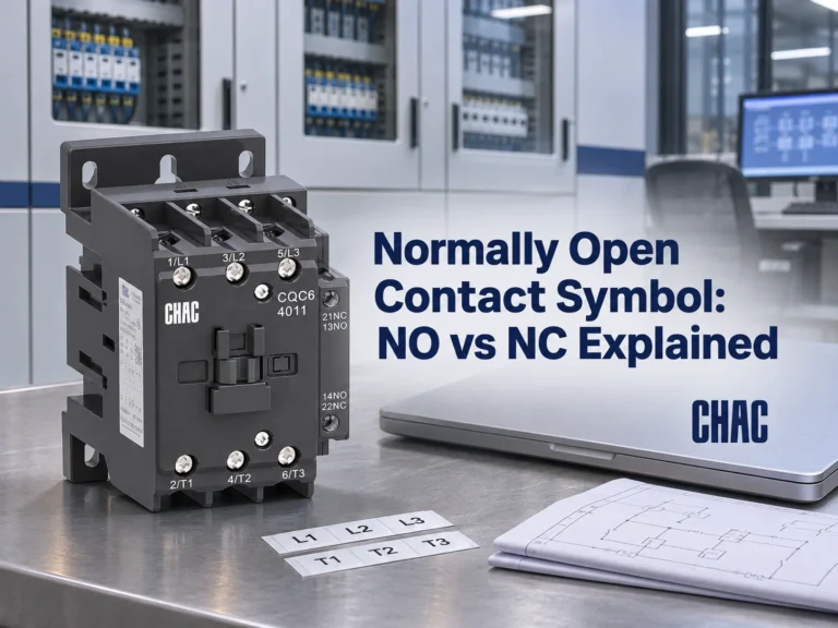
Inżynier zakupów otrzymuje schemat jednoliniowy z oznaczeniem wyłącznika odłączającego i zamawia urządzenie o odpowiedniej klasie prądowej. Podczas przeglądu projektu zespół odkrywa, że przewidziane obciążenie obejmuje również przełączanie obciążenia silnikowego, podczas gdy w ofercie wskazano jedynie funkcję izolacji. Ta poglądowa sytuacja pokazuje, dlaczego rozpoznanie symbolu to zaledwie pierwszy krok.
Podsumowanie: The symbol elektryczny dla wyłącznika zabezpieczającego oznacza funkcję przełączania lub izolacji w ramach konwencji rysunkowej. Odczytuj go razem z legendą, oznaczeniem urządzenia i harmonogramem sprzętu. Rysunki IEC 60617-style oraz północnoamerykańskie schematy drabinkowe mogą różnie przedstawiać tę samą funkcję, podczas gdy rzeczywiste urządzenie musi spełniać określone wymagania dotyczące napięcia, obciążenia przełączania i izolacji.
Jak legenda rysunku identyfikuje wyłącznik bez obciążenia
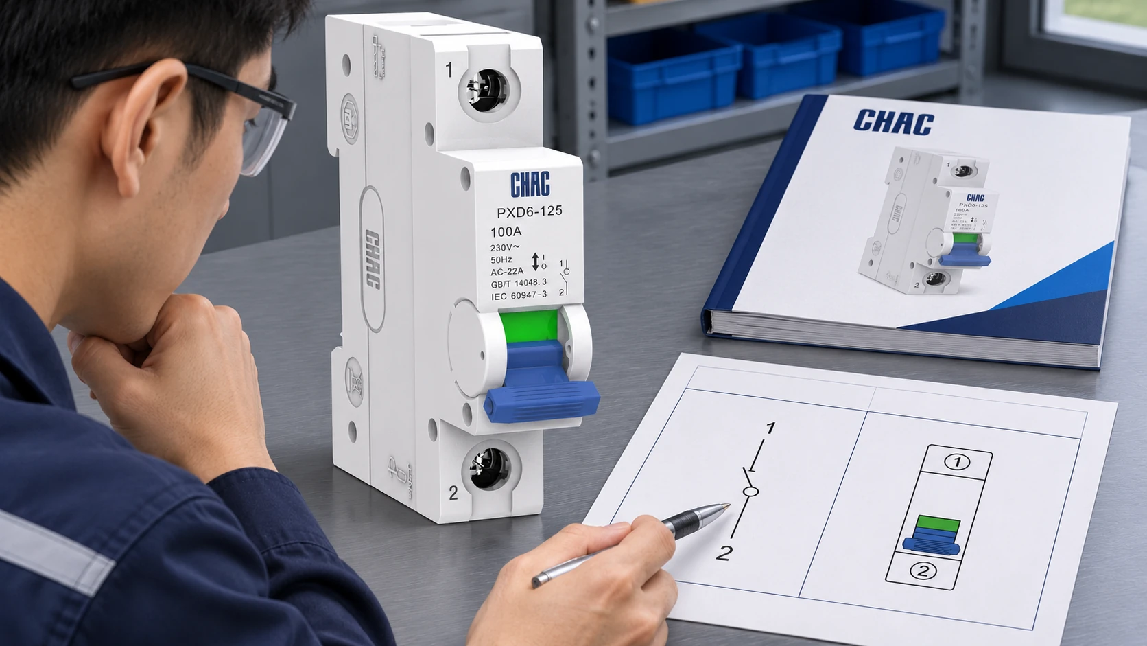
Podstawowa symbolika wyłącznika zazwyczaj obejmuje ruchomy styk i widoczny przerwę w stanie rozwartym. Ta wizualna cecha przekazuje informację o rozłączeniu. Dokładny sposób wykonania linii, dodatkowe znaki oraz oznaczenie urządzenia zależą od biblioteki rysunkowej i zasad projektowych. Nie identyfikuj urządzenia na podstawie pojedynczej linii ukośnej bez sprawdzenia legendy.
Biblioteka symboli IEC-60617 firmy Autodesk dzieli wyłączniki i rozłączniki, przekaźniki i kontakty oraz bezpieczniki na różne grupy. Te grupy są przydatne podczas przeglądania rysunku, jednak nazwa bloku CAD nie stanowi specyfikacji zakupowej. Harmonogram projektu powinien określać funkcję urządzenia oraz obowiązującą normę produktową, np. IEC 60947-3 dla odpowiednich wyłączników i rozłączników.
Rozpocznij od trzech elementów: legendy, unikalnego znacznika urządzenia i wpisu w harmonogramie. Jeśli symbol jest oznaczony jako QS1 na jednym rysunku, najpierw znajdź ten dokładnie taki sam znacznik w innym miejscu, zanim założysz, że inny podobny symbol reprezentuje to samo urządzenie. Konwencje oznaczania różnią się, więc QS1 jest przykładem, a nie obowiązkową oznaką.
Wiele schematów przedstawia kontakty przełącznikowe w stanie normalnym lub w pozycji spoczynkowej. Specjalne diagramy działania mogą zamiast tego ukazywać określony stan systemu. Przed uznaniem widocznego kontaktu otwartego za polecenie jego aktywacji należy zapoznać się z uwagami dotyczącymi pozycji roboczej, blokad mechanicznych oraz warunków awaryjnych.
Jak rozróżnić symbole wyłącznika, wyłącznika z bezpiecznikiem i wyłącznika automatycznego?
A rozdzielacz z wyłącznikiem Połącza funkcję przełączania z odpowiedniością do izolacji w zakresie swoich deklarowanych parametrów. Rozłącznik, który ma służyć przede wszystkim do izolacji, nie może być automatycznie traktowany jako zdolny do rozrywania każdego obciążenia. Wyłącznik dodatkowo pełni funkcję automatycznego zabezpieczenia, jednak jego odpowiedniość do izolacji oraz ograniczenia dotyczące pracy wciąż wymagają potwierdzenia.
| Identyfikacja rysunku | Czego szukać | Co kupujący musi potwierdzić |
|---|---|---|
| Rozłącznik niezespawany | Przedstawienie styku przełączającego bez elementu bezpiecznikowego w podanym zespole | Isolation function, load-switching duty and upstream protection |
| Złączone odłączniki | Switching element and separately identifiable fuse symbols or fuse designation | Fuse class, size, ratings, replacement access and complete assembly data |
| Przekaźnik | Protective switching designation and the project-specific breaker symbol | Trip characteristics, interrupting rating and isolation suitability |
| Contactor or control relay | Coil reference linked to operating contacts | Control function and contact duty, without assuming energy isolation |
The fuse does not disappear merely because a drawing shows it in another location. Some one-line diagrams place protective components separately for clarity. Read the enclosure boundary and bill of materials to establish whether the fuse and switch are supplied together or as separate items.
Conversely, a diagram that contains a fuse elsewhere does not prove that the disconnect itself is a fused model. This matters commercially: a quotation may exclude fuse links, a handle mechanism or an enclosure even though the design drawing shows a complete functional arrangement.
Trace the same disconnect through power and control drawings
A three-phase disconnect can be drawn as three mechanically linked poles on a detailed schematic. A single-line diagram may use one symbol with a pole designation because one line represents the three-phase circuit. Count physical poles from the schedule, not from the number of lines on the page.
Follow the power path from the source through protection, disconnecting equipment and the load. Then cross-reference the same device in the control schematic. An auxiliary contact there can report position or participate in an interlock. It is not the main power contact, and its presence does not establish the number of switched power poles.
For a useful document check, record the drawing number and revision next to each device tag. A mismatch between an old control drawing and a new power drawing is often more consequential than a minor difference in symbol shape. Resolve conflicting pole counts or functions before releasing the order.
| Document | Question it answers | Useful cross-check |
|---|---|---|
| Single-line diagram | Where is the disconnect in the distribution system? | Source, load and upstream protection |
| Detailed power schematic | Which conductors and poles are represented? | Mechanical linkage and neutral arrangement |
| Control schematic | Which control signals refer to this device? | Auxiliary contact tags and reference locations |
| Equipment schedule | What must be purchased? | Model, duty, voltage, pole count and accessories |
| Manufacturer instructions | How may the selected model be applied? | Operating limits, mounting and isolation provisions |
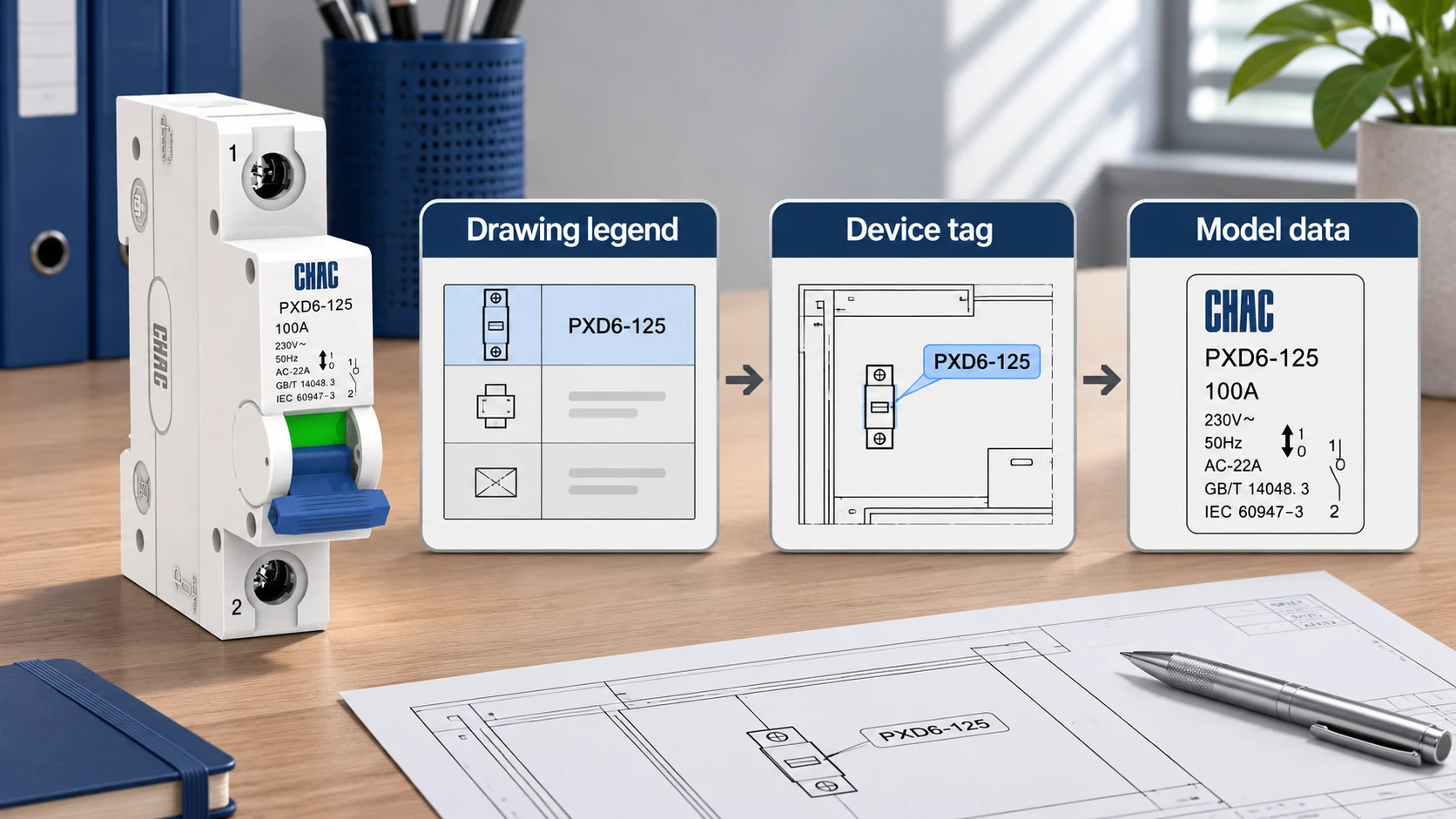
Why an open disconnect symbol does not prove safe isolation
The I and O markings commonly indicate on and off positions. They are equipment markings, not a substitute for a schematic legend or a verified isolation procedure. A handle position alone does not establish that all hazardous energy sources have been removed, particularly where there are alternate supplies or stored energy.
OSHA’s hazardous-energy control rule, 29 CFR 1910.147, explicitly distinguishes energy-isolating devices from push buttons, selector switches and other control-circuit devices. The rule is a useful reminder that opening a control contact and physically isolating energy are different actions. Its legal application depends on the workplace and activity involved.
IEC 60947-3 and IEC 60947-2 address different product families and functions. A familiar breaker symbol does not make a device interchangeable with a specified switch-disconnector. For related selection distinctions, see the zakres wyłączników różnicowoprądowych miniaturyzowanych, then return to the disconnecting duty stated in the project specification.
Use the drawing to specify the disconnect's duty and accessories
Send the supplier the relevant drawing excerpt with its legend, not an isolated screenshot of the symbol. Include system voltage and frequency, AC or DC duty, switched conductors, load type, expected operating duty, enclosure needs and required isolation provisions. Identify accessories separately so the offer can be checked line by line.
CHAC PXD6-125 DSL isolator provides a starting point for discussing an isolating-switch requirement. Its model data must be compared with the application. Neither the product photograph nor the symbol in this guide establishes suitability for every disconnecting or switching task.
Ask for exceptions to be stated in the quotation. A model that meets the current rating but needs a different operating mechanism can affect enclosure layout, installation labor and spare-parts planning. Resolving that detail before purchasing is usually easier than changing the drawing after the panel has been built.
Common questions about disconnect symbols
What is the symbol for a disconnector switch?
It commonly uses an open switching-contact representation, with additional features determined by the drawing convention. Check the project legend and device schedule to distinguish a disconnector from a switch-disconnector or circuit breaker.
How do fused and non-fused disconnect symbols differ?
A fused arrangement includes identifiable fuse elements or a fuse designation in addition to the switching function. The fuses may be shown separately, so check the assembly boundary and bill of materials before deciding what the symbol includes.
How can you distinguish a circuit breaker symbol from a disconnect symbol?
Use the legend, protective-device designation and schedule entry together. A circuit breaker has an automatic protective role, whereas a disconnect symbol alone does not establish overload or short-circuit protection.
How is a three-phase disconnect shown on a wiring diagram?
A detailed diagram can show three linked switching poles. A single-line diagram may show one symbol with a three-pole designation, so do not infer the physical pole count from the drawing lines alone.
Is an isolator symbol the same as a disconnect switch symbol?
The terms may describe closely related functions, but usage differs between markets and standards. Confirm the required isolation and load-switching duties rather than treating the names or graphic shapes as proof of equivalence.
Are disconnect symbols drawn in the open or closed position?
They are often shown open or in a stated normal reference condition. Operating-state drawings can differ, so the notes and legend take priority over a general convention.
What do the I and O markings mean on a disconnect switch?
I generally indicates on and O indicates off. Those position markings do not replace verification of isolation, especially where another source or stored energy could remain present.
Przypisy
- Autodesk: IEC-60617 symbol library categories
- 29 CFR 1910.147: hazardous-energy control
- IEC 60947-2: circuit-breaker standard scope
A readable drawing should lead to an unambiguous device requirement. Skontaktuj się z CHAC with the legend, device tag and duty requirements to discuss the appropriate isolator configuration.