Kalkulator do doboru wyłączników DC
Oblicz prąd projektowy prądu stałego i sprawdź podany wyłącznik przeciążeniowy pod kątem przekroju kabla, maksymalnego napięcia źródła, zdolności doznoszenia zwarć DC oraz potwierdzenia odpowiedniego połączenia biegunów.
Oblicz prąd projektowy prądu stałego i porównaj podany wyłącznik z nośnością kabla, maksymalnym napięciem źródła oraz przewidywanym prądem zwarciowym.
Wynik
Nominalny prąd stały referencyjny
50.00AKontrole numeryczne zakończone pomyślnie; okablowanie DC nadal nie zostało zweryfikowane.I = P × 1,000 / V; Idesign = I × factor; In ≥ Idesign and In ≤ IzOkrągła wartość klasyfikacji jest referencją ogólną, a nie wyborem modelu CHAC. Do określenia rzeczywistego napięcia i rozmieszczenia biegunów należy wykorzystać dane dotyczące przerwania prądu stałego. Nie mnożyć napięcia na jeden biegun przez liczbę biegunów bez zaopatrzenia się w zatwierdzony schemat.
Dlaczego ten wynik?
Formuła i metoda
Oblicz prąd projektowy prądu stałego i sprawdź podany wyłącznik przeciążeniowy pod kątem przekroju kabla, maksymalnego napięcia źródła, zdolności doznoszenia zwarć DC oraz potwierdzenia odpowiedniego połączenia biegunów.
Jak używać tego kalkulatora
- Wprowadź rzeczywistą moc elektryczną DC na wejściu oraz napięcie robocze. Do sprawdzenia napięcia urządzenia użyj maksymalnego napięcia zasilania.
- Wprowadź wartości znamionowe dokładnie dla danego wyłącznika oraz skorygowaną przepustowość kabla.
- Potwierdź polaryzację, sposób podłączenia biegunów oraz obciążalność w przypadku zwarć prądu stałego, korzystając z diagramu producenta i danych dotyczących przerwania obciążenia.
Granice obliczeniowe
Nie oblicza prądu zwarciowego baterii/cell fotowoltaicznych, napięcia otwartego zimnego ogniwa fotowoltaicznego, stałych czasowych, prądu rozruchowego ani dopuszczalnego prądu ograniczonego. Ogólna seria prądowa nie stanowi deklaracji dostępności produktu.
Dobór wymiarów wyłącznika DC: prąd, napięcie i zdolność przeładowcza
Wybór wyłącznika DC wymaga uwzględnienia nie tylko prądu obciążenia. Maksymalne napięcie źródła akumulatorowego lub fotowoltaicznego może przekraczać napięcie znamionowe, a deklarowana zdolność do przerwania obciążenia dotyczy określonego napięcia DC, układu biegunów oraz charakterystyki pracy obwodu.
Notatki wprowadzane
| Wprowadzenie | Czego należy się zorientować |
|---|---|
| Moc i napięcie zasilania | Wprowadź wejście prądu stałego. Kalkulator dzieli moc wejściową w watów przez napięcie robocze; nie szacuje sprawności przetwornicy ani silnika. |
| Maksymalne napięcie źródłowe | Use the maximum circuit voltage for the device voltage comparison. PV cold Voc and battery charging limits must be established separately. |
| Current, fault and wiring data | Use corrected cable capacity and actual DC device ratings. Mark the pole/polarity diagram verified only after reviewing the exact manufacturer instructions. |
Przykładowe rozwiązanie · wartości początkowe
2 kW DC load on a 48 V circuit
Factor 1.00 · maximum source 60 V · candidate 50 A / 125 V DC / 10 kA · cable Iz 63 A · fault 6 kA
I = 2,000 / 48 = 41.67 A; the next generic listed rating is 50 A.
41.67 A ≤ 50 A ≤ 63 A; 60 V ≤ 125 V; 6 kA ≤ 10 kA.
50.00 A
The example’s numeric checks are met. Polarity and series-pole wiring remain unverified at the initial settings, so the tool does not present a complete approval.
DC breaker sizing from watts and operating voltage
For a DC load specified by electrical input power, current is I = P / V. A 2,000 W load at 48 V draws approximately 41.67 A. Apply the sizing factor required by the actual design, then compare the resulting design current with the protective device and corrected cable capacity.
The default factor of 1.00 is an example, not a universal installation allowance. If the load specification gives output power, account for conversion losses before entering electrical input power. Inrush, continuous duty and temperature can also affect the final device choice.
Solar DC circuit breakers: nominal voltage is not enough
A solar DC circuit breaker must be assessed against the array’s maximum circuit voltage, not just its nominal operating voltage. Establish cold-condition string open-circuit voltage separately. PV circuit protection also needs array and module data, including the relevant current and reverse-current conditions.
Battery circuits need the same distinction between normal operating voltage and maximum source voltage, together with a prospective fault-current assessment. This tool accepts those established values; it does not calculate PV string voltage or battery short-circuit current.
Check the DC rating and the permitted pole connection together
DC interruption capability belongs to a stated voltage and test duty. An AC breaking rating cannot establish DC suitability, and two poles do not automatically double the allowable voltage. Use the manufacturer’s exact series-pole and polarity diagram.
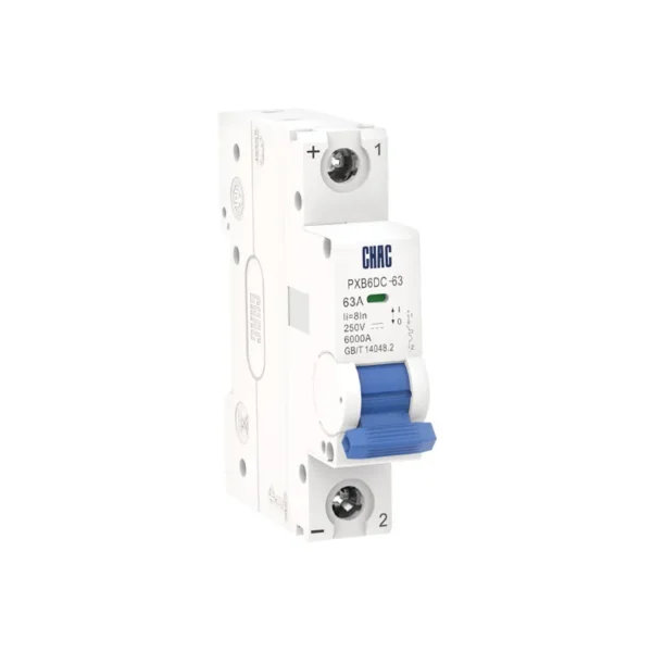
For PXB6DC-63, review the published DC voltage limits and connection requirements for the intended arrangement. The calculator’s generic ampere result is a rating reference, not a selected PXB6DC-63 model. Confirm the declared breaking capability at that voltage before accepting the numeric comparison.
Use the exact DC connection data
- Do not infer DC suitability from an AC breaking rating. Do not multiply a per-pole voltage by pole count unless the exact manufacturer diagram permits that arrangement.
- Starting current, circuit time constant, current-limiting energy, upstream/downstream coordination and maximum source voltage require the relevant circuit study and product data.
Często zadawane pytania
Why enter both operating and maximum source voltage?
Operating voltage is used for the load-current estimate. Maximum source voltage is used to check the device’s DC voltage duty.
Does the 50 A result select PXB6DC-63?
No. It is a generic rounded current reference. A product choice also needs the exact DC voltage, pole diagram, fault duty and installation data.
Can this calculate battery short-circuit current?
No. Prospective fault current is an input from a suitable study or source data. Battery impedance, state of charge and connections are not modeled here.
Does the sizing factor always need to be 1.25?
No universal multiplier is applied. Use a factor justified by the relevant circuit duty and installation rules.
Can this size a solar DC circuit breaker from panel watts alone?
No. A PV design also needs string voltage under the relevant temperature conditions, array currents, module limits and connection details. Enter verified circuit values; a watts-to-amps calculation does not establish the complete PV protection requirement.
Is a 48 V battery circuit always below 48 V?
No. Operating and charging conditions can produce a higher voltage. Use the established maximum battery-system voltage when checking the DC breaker’s voltage rating, and operating voltage for the current estimate.
Potrzebujesz pomocy przy wyborze produktu CHAC?
W swoim zapytaniu należy podać napięcie zasilania, prąd obciążenia oraz warunki montażu.
Przykład zastosowania · Wykresowe dane wejściowe
Reviewing a 48 V DC feeder against PXB6DC-63 data
A 3 kW DC load at 48 V draws 62.50 A, giving a 63 A reference with the factor set to 1.00. The CHAC PXB6DC-63 table includes 63 A, lists DC125V among its 1P voltage options, and declares 10 kA Icu and 7.5 kA Ics. For this example, a 60 V maximum system voltage and 5 kA fault level can be compared with those entered ratings. The result still leaves the exact voltage variant, pole diagram and source fault behavior to verify. A constant-power load operating below 48 V also needs a higher-current check.
Dane produktu: PXB6DC-63 Miniatura przełącznika obwodowego
Powiązane produkty CHAC
Compare DC breaker ratings with the circuit voltage, current, fault level and pole arrangement.