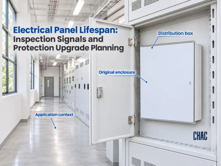
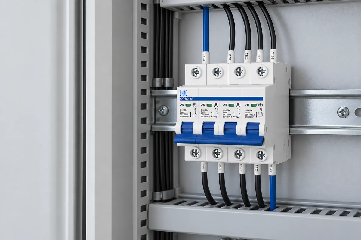
Disjuntor instalação em um quadro de distribuição Trata-se de uma tarefa de compatibilidade e verificação, e não de simplesmente selecionar o disjuntor de maior capacidade disponível. O instalador deve adequar o disjuntor à placa listada, à capacidade de condução de corrente do condutor, ao nível de curto-circuito, à configuração dos polos, aos limites dos terminais, às condições da caixa e ao processo de inspeção local. Um registro consistente das etapas de isolamento, aperto com torque, ensaios e rotulagem facilita a aprovação e a manutenção da instalação.
O que deve ser confirmado antes da instalação?
Confirm the board or panel model, its listing and available spaces, the circuit purpose, supply arrangement, conductor size, expected load, available fault current, and the required breaker pole configuration. Also confirm whether a permit, inspection, or utility coordination step is required. A breaker that fits the rail can still be unsuitable for the board or the protective function. The work scope matters too: how to install a circuit breaker within an existing board differs from how to install a circuit breaker panel, which also involves its incoming supply and distribution arrangement. A qualified installer should confirm which work is covered.
For commercial and export work, retain the approved single-line diagram, panel schedule, product datasheet, and installation instructions together. CHAC’s equipamento de distribuição elétrica category and CQMG20C distribution box page can provide product context, while the project documents control the final selection.
Como um disjuntor deve ser dimensionado em relação à quadro de distribuição e ao condutor?
| Verifique | Pergunta para responder | Registar |
|---|---|---|
| Board compatibility | Is the breaker listed or approved for this board and mounting arrangement? | Panel schedule and compatibility evidence |
| Conductor protection | Does the rating protect the installed conductor under the adopted code? | Load calculation and conductor data |
| Corrente de defeito | Does the interrupting rating meet the available fault current? | Fault study or design value |
| Terminais | Do conductor size, material, strip length, and torque match the instructions? | Installation manual and torque record |
| Ambiente | Are heat, moisture, contamination, spacing, and enclosure conditions acceptable? | Site review and enclosure information |
Do not increase the breaker rating to stop nuisance trips before finding the cause. The change can leave the conductor or board outside its permitted protection range.
Qual é a sequência de instalação segura?
- Review the approved drawing, permit requirements, and manufacturer instructions.
- Isolate the supply using the site procedure, lock out the source where required, and verify absence of voltage with an appropriate instrument. A breaker in the OFF position is not proof that the whole work area is de-energized.
- Inspect the board, rail, terminals, conductors, and protective bonding before fitting the device.
- Install the correct pole configuration and route conductors without exceeding bending, fill, or terminal limits.
- Torque each termination to the published value using a suitable calibrated tool; do not estimate by feel.
- Check labels, covers, clearances, and the mechanical operation before testing.
- Complete the tests required by the device, board, and local code, then document the results before energizing.

What will an inspector or AHJ want to see?
Inspection expectations vary by jurisdiction, but the evidence normally needs to connect the installed device to the approved design. Keep the board listing, breaker model, conductor information, circuit labels, torque value, test method, test results, and any required permit or inspection record in one handover file. If a product substitution occurred, record who approved it and which technical document supports it.
Standards do not replace the site procedure. The applicable edition of NFPA 70, an IEC-based installation code, or another local rule must be confirmed for the project. CHAC’s Gamma de MCB can be reviewed only after those conditions are known.
How should the completed board be handed over?
Provide the final single-line diagram, panel schedule, product datasheets, test results, torque record, circuit labels, and maintenance instructions. Add dated photos of the nameplate and terminations when the project procedure permits. Note any unused spaces, spare circuits, or assumptions so a future installer does not treat an incomplete record as a complete design.
FAQs
What are the requirements for circuit breaker installation?
Match the breaker to the listed board, conductor, fault level, pole arrangement, terminals, enclosure, and adopted installation code. Then isolate, torque, test, label, and document the work.
Can I add a circuit to a full breaker box?
Only after confirming available spaces, busbar and enclosure limits, load capacity, conductor routing, and any permit or inspection requirements. A crowded box is not solved by forcing in a device.
How should a breaker be matched to the panel and conductor?
Use the board compatibility information, conductor ampacity, load calculation, fault current, and terminal instructions together. A physical fit is not proof of electrical compatibility.
Who should install a new circuit breaker?
A qualified person who is authorized under the local rules should perform or supervise the work. The required qualification and inspection process depend on the jurisdiction and installation type.
How is a new breaker torque-tested after installation?
Use the manufacturer’s published torque value and an appropriate calibrated torque tool, then record the device, terminal, value, tool, date, and installer. Do not substitute a generic torque value.
Fontes para normas e verificação adicional
- NFPA 70, National Electrical Code information
- UL Solutions standards and certification guidance
- International Electrotechnical Commission standards portal
Decision principle: safe disjuntor instalação em um quadro de distribuição follows the approved board, conductor, fault, torque, testing, and inspection evidence in that order. For model documentation, use CHAC’s technical contact channel after the project inputs are complete.