A contactor can respond correctly to a start command yet leave a motor-control panel with the wrong restart behavior. A maintained command, an incorrectly assigned auxiliary contact, or a misunderstood overload reset can change what happens after a trip or supply interruption. These are control-sequence questions, not simply wire-placement questions. Panel builders need a drawing that explains both the load path and the conditions permitting coil energization, followed by acceptance checks against the installed variant. This guide separates those checks so that a successful no-load demonstration is not mistaken for proof of loaded operation.
The short answer is to review the power path, coil supply, command logic, protective trip response, and feedback separately. Two-wire maintained control and momentary-start seal-in control can behave differently when power returns; neither should be accepted without a defined restart requirement. The selected contactor and accessory instructions govern terminal assignments and ratings. Before commissioning, a qualified engineer should approve the sequence, verify safe isolation under the applicable procedures, and establish the test conditions. This is not a universal wiring diagram or a guide to live electrical work.
Contents
- What should the drawing establish first?
- Which coil and suppression details need confirmation?
- How do maintained and seal-in commands differ?
- What can auxiliary contacts and interlocks prove?
- Which sequence checks belong in commissioning?
- How should symptoms guide the next check?
- What evidence is needed before panel release?
- Часто задаваемые вопросы
What should the drawing establish first?
The main contacts of an AC contactor switch the load path. The coil belongs to a separate command path, potentially supplied from a different source. Opening that command path is therefore not proof that every power conductor is isolated.
Trace each source and return on the approved drawing. Identify the coil, stop function, permissives, protective trip contact, and auxiliary functions without borrowing terminal numbers from another model. The drawing should state what enables operation and what removes the command, including loss of the control supply. A permissive is a required operating condition; its restoration must be considered alongside the restart requirement.
Which coil and suppression details need confirmation?
Match the exact coil variant to its specified supply type, voltage, frequency where applicable, and manufacturer operating limits. Check the controller output and any interface device against the coil’s documented demand. A family name or matching enclosure does not establish these details.
A suppression accessory can influence coil release timing, so its presence, compatibility, and effect belong in the sequence review. Do not assume interchangeable suppressors or universal release times. Use the selected accessory documentation when evaluating interlock transitions or delayed feedback. For the selection background, see contactor coil voltage selection for OEM panels.
How do maintained and seal-in commands differ?
A typical two-wire command remains asserted while its controlling contact is closed. If supply or a permissive returns while that command remains present, the coil may energize again. Whether it does depends on the complete circuit and controller behavior.
In a conventional momentary-start arrangement, a normally open auxiliary contact may maintain, or seal in, the command after the start input is released. Stop and trip functions must interrupt the intended command path. Confirm NO and NC states from the device documentation and drawing convention; these labels alone do not describe the entire operating sequence.
Where deliberate restart is required, the design must prevent a restored supply, permissive, or protective reset from substituting for a new start action. Review retained controller outputs and any parallel paths that could defeat that requirement.
What can auxiliary contacts and interlocks prove?
Assign every auxiliary contact a specific job: seal-in, indication, electrical interlocking, or feedback. Confirm its contact arrangement, rating, mounting compatibility, and represented state. For mutually exclusive commands, review electrical logic and any required mechanical interlock together; suppression-related release delay can matter at transitions.
Feedback indicates only the state its mechanism is designed to represent. It is not an absence-of-voltage test, and an ordinary auxiliary contact is not automatically safety-rated feedback. Schneider Electric’s PowerPact FAQ distinguishes position indication from trip-alarm indication for those breaker accessories; that distinction illustrates why accessory meanings must be verified, not transferred to contactors (source).
Which sequence checks belong in commissioning?
Define acceptance outcomes before an authorized commissioning program begins. The table is a review framework, not an instruction to manipulate an energized panel.
| Decision or condition | Expected sequence to establish | Evidence to record |
|---|---|---|
| Start and stop | Start requires the stated permissives; stop removes the intended command | Approved logic and observed command/feedback agreement |
| Control-supply interruption | Recovery follows the maintained-command or deliberate-restart requirement | Controller retention settings and recovery result |
| Overload trip | The designated trip contact interrupts the intended coil path | Exact relay instructions and approved protective-function test |
| Overload reset | Reset restores relay availability; restart follows separately defined logic | Reset mode, command state, and resulting behavior |
| Interlock transition | Conflicting commands are prevented as designed | Accessory compatibility and transition behavior |
| Loaded operation | The assembly satisfies its intended operating conditions | Project-specific acceptance criteria and recorded results |
Ан overload relay reset is not synonymous with a motor restart. Schneider Electric states that LRD bimetal relay reset time depends on trip severity, hot or cold condition, and ambient conditions rather than a fixed interval (source). Automatic reset does not prove automatic restart; the remaining command logic determines that risk. A no-load check cannot establish loaded performance.
How should symptoms guide the next check?
| Symptom | Review priority | Boundary |
|---|---|---|
| Fails to pick up | Coil variant, command source, permissives, and interface capability | Do not bypass protective logic to obtain operation |
| Chatter or abnormal noise | Supply suitability and model-specific mechanical causes | Normal hum is not necessarily chatter |
| Unexpected restart | Maintained command, retained output, reset mode, and parallel paths | Reconcile behavior with the approved restart requirement |
| Feedback mismatch | Accessory function, contact assignment, and transition timing | Do not interpret indication as electrical isolation |
For Type S NEMA contactors, Schneider Electric identifies inadequate voltage, an incorrect coil, a broken shading coil, contamination, misalignment, binding, or mounting as possible noise causes (source). That model-specific guidance is not a universal diagnostic rule or an IEC coil-voltage limit.
What evidence is needed before panel release?
Release the panel against an approved control circuit revision, installed component identifiers, accessory instructions, and commissioning records. Unresolved restart or feedback behavior requires engineering review, not an assumption based on appearance.
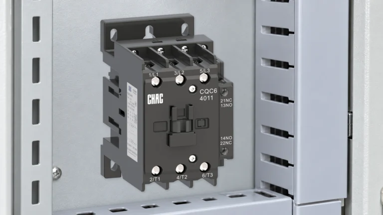
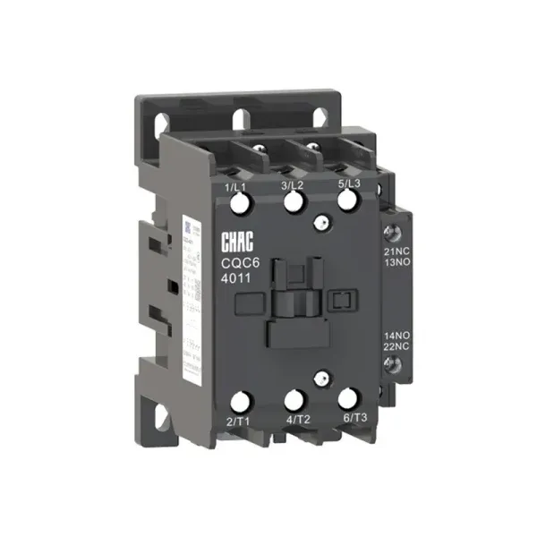
CHAC’s CQC6 industrial AC contactor page provides a starting point for remote-switching and motor-control product discussions. For protective-device coordination, request the exact variant documentation through the CQR2 thermal overload relay product route. Neither page replaces project-specific compatibility checks.
Часто задаваемые вопросы
Can one contactor diagram cover every model?
No. Coil variants, accessories, and terminal assignments require the selected model’s instructions.
Does a seal-in contact guarantee deliberate restart?
No. Parallel commands or retained controller outputs can change recovery behavior; review the complete logic.
Does automatic overload reset restart the motor?
Not necessarily. Restart depends on whether the control system still supplies an operating command.
How long should a thermal relay take to reset?
There is no universal interval. Use the exact relay instructions and consider its thermal condition.
Does auxiliary feedback prove the power contacts are safely isolated?
No. Follow the applicable isolation and verification procedure; indication is not absence-of-voltage proof.
Is a successful no-load test enough for panel acceptance?
No. It verifies only the conditions tested, not load-dependent behavior or complete application suitability.
Ссылки
- Schneider Electric FA93442: Type S NEMA contactor noise causes, modified May 12, 2026.
- Schneider Electric FAQ000133310: LRD bimetal relay reset time, modified August 11, 2026.
- Schneider Electric FA115016: PowerPact position and alarm accessory functions, modified October 21, 2022.
What is the final acceptance principle?
A panel is not ready because its contactor closes once. It is ready when the installed components and approved logic produce the required behavior across starting, stopping, interruption, trip, reset, and recovery. Confirm the exact coil and accessories first, then establish command priorities and restart conditions, and finally record the relevant acceptance results. Keep indication separate from isolation and no-load evidence separate from loaded-operation evidence. These distinctions prevent a convenient demonstration from becoming an unsupported release decision. For a CHAC component review, связаться с CHAC Electric with the schematic, exact variants, and unresolved interface questions.