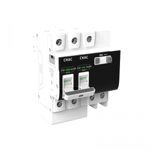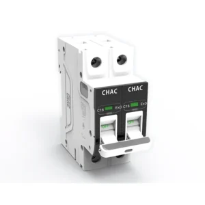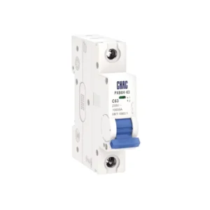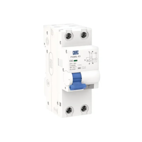
PXB6L-63 Residual Current Circuit Breaker with Overcurrent Protection – Electronic Type
The PXB6L-63 RCBO provides overload, short-circuit and residual-current protection within its published 6A–63A range. Selection should be based on the circuit voltage, conductor, load behaviour, prospective fault current and applicable installation rules—not the ampere rating alone.
Product Overview
PXB6L-63 is an RCBO for 230/400V AC distribution circuits. It combines thermal-magnetic overcurrent protection with residual-current protection in one device. The published range covers 6A–63A, 1P+N / 3P+N, B / C / D curves and 30 / 50 / 100 / 300mA sensitivity options. The saved model data describes the residual-current or construction type as Type AC / Type A; electronic construction.
The PXB6L-63 supports 3 phase RCBO projects through its 3P+N RCBO option, alongside a separate 1P+N configuration.
The saved model record lists IEC 61009-1; GB/T 16917.1 as the applicable standard reference. It also lists CCC certification; scope must be confirmed for the ordered configuration.
Key Features
Typical Applications
Typical use is in final or sub-distribution circuits where both overcurrent and residual-current protection are required. The project must still confirm the expected residual-current waveform, sensitivity, neutral arrangement, pole configuration, fault level, conductor size, enclosure conditions and local wiring rules.
Applications and Selection Guide
Use the verified model values below to create a shortlist, then validate the complete circuit. Product ratings do not replace conductor calculations, a fault-current study, coordination review or local installation requirements.
| Selection point | PXB6L-63 reference | What the project must confirm |
|---|---|---|
| Rated current | 6A–63A | Design current, conductor ampacity, installation method, ambient temperature and grouping |
| Voltage and frequency | 230/400V AC; 50/60Hz | Supply system and equipment rating |
| Pole configuration | 1P+N / 3P+N | Conductors to be switched/protected, including neutral treatment |
| Trip curve | B / C / D | Load inrush and required disconnection performance |
| Residual-current selection | 30 / 50 / 100 / 300mA; Type AC / Type A; electronic construction | Expected waveform, sensitivity, purpose and local rules |
| Breaking capacity | 6kA Ics | Prospective short-circuit current and protection coordination |
Protection Scope
An RCBO combines overcurrent and residual-current protection; it is not simply an MCB with a different label.
MCB vs RCBO
Compare Protection Functions →
Residual-Current Selection
Published options: 30 / 50 / 100 / 300mA. Confirm sensitivity and waveform type for the actual circuit and market.
Sensitivity & Type
Review Selection Support →
Breaking Capacity and Curve
6kA Ics; B / C / D curves. Both fault level and load inrush must be checked.
Fault Level & Inrush
Compare Breaking Capacity →
Pole and Wiring Arrangement
Published pole options: 1P+N / 3P+N. Use the exact model diagram; do not assume neutral routing.
Poles & Neutral
Confirm Wiring Data →
Ordering Guide
- Specify the exact model: PXB6L-63.
- State the required current rating within 6A–63A.
- Confirm pole arrangement: 1P+N / 3P+N.
- Confirm trip curve: B / C / D.
- Confirm residual-current sensitivity and type from the published 30 / 50 / 100 / 300mA options.
- Provide system voltage, expected fault level, destination market, quantity and document requirements.
Installation and Coordination Checks
- Use the exact model drawing and instructions; do not infer supply direction, neutral routing or terminal positions from another product.
- Verify conductor material and cross-section against the circuit calculation and published terminal data.
- Confirm fault level, upstream/downstream coordination, enclosure temperature, grouping, altitude and clearances.
- Installation, isolation, testing and maintenance must be carried out by qualified personnel under applicable rules.
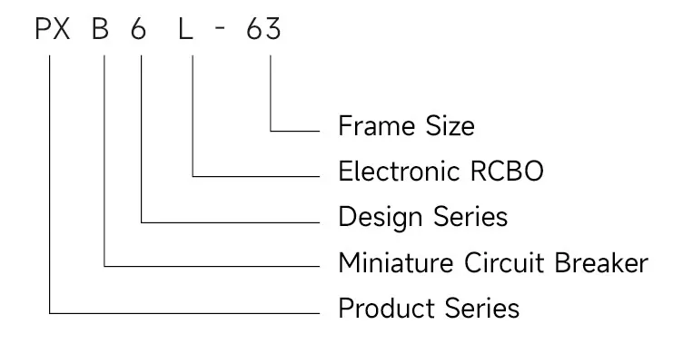
Type designation
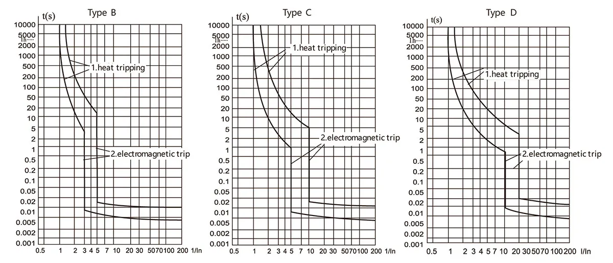
Tripping curves
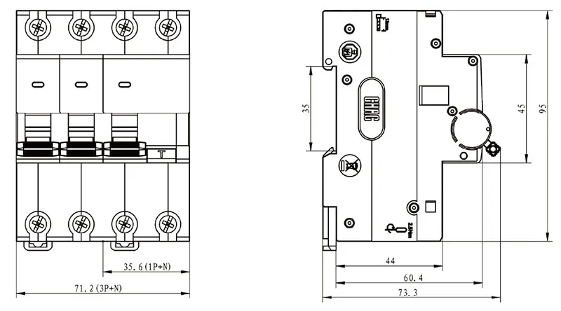
Dimensions(mm)
Technical Specifications
| Parameter | |
| Rated Voltage (V) | 230V~(1P+N)/400V~(3P+N) |
| Rated Current (A) | 6, 10, 16, 20, 25, 32, 40, 50, 63 |
| Number of Poles | 1P+N, 3P+N |
| Rated Short-Circuit Breaking Capacity Ics (A) | 6000A |
| Rated Residual Operating Current IΔn (mA) | 30, 50, 100, 300 |
| Rated Residual Non-Operating Current ΔIΔno (mA) | 0.5IΔn |
| Rated Residual Make and Break Capacity IΔm (A) | 2000A |
| Residual Current Tripping Threshold | ≤0.1s |
| Residual Current Trip Type | AC Type, A Type |
| Mechanical Life | ≥15000 |
| Electrical Life | ≥10000 |
| Tripping curves | B, C, D |
| Pollution Degree | 2 |
| Protection Class | IP 20 |
| Installation Category | Ⅲ |
| Standards | IEC61009-1, GB/T16917.1 |
| Certification | CCC |
Tripping Characteristics (Reference Temperature: 30°C)
| Item | Tripping Curve | Test Current (A) | Initial Status | Time limit for tripping or non-tripping | Expected result | Remarks |
| Delay | ≤63 | Cold | 1.13In | ≤1h | Non-tripping | |
| Delay | ≤63 | Following previous test | 1.45In | <1h | Tripping | Current smoothly rises to specified value in 5s |
| Delay | ≤32 | Cold | 2.55In | 1<t<60s | Tripping | |
| Delay | >32 | Cold | 2.55In | 1<t<120s | Tripping | |
| Instantaneous | Any value | Cold | 3, 5, 10In | ≤0.1s | Non-tripping | B, C, D |
| Instantaneous | Any value | Cold | 5, 10, 20In | <0.1s | Tripping | B, C, D |
Note: The term “cold” means that the test is carried out at a reference calibration temperature without load before the test.
Conductor requirements and cross section
| Copper cross-section(mm²) | Rated current In(A) |
| 1 | In≤6 |
| 1.5 | 6 < In≤13 |
| 2.5 | 13 < In≤20 |
| 4 | 20 < In≤25 |
| 6 | 25 < In≤32 |
| 10 | 32 < In≤50 |
| 16 | 50 < In≤63 |
Why Choose CHAC
With 30+ years of manufacturing experience, 1100+ employees, 100M+ poles
annual capacity and 90% automated production, CHAC provides stable production capacity and strict
quality control for global OEM/ODM customers. Our in-house manufacturing system supports long-term
cooperation for electrical brands, importers and distributors.

30+
YEARS EXPERIENCE
Specialized in low-voltage electrical manufacturing

1100+
EMPLOYEES
Professional team ensures stable quality and delivery

100M+
POLES ANNUAL CAPACITY
Large-scale production capacity to meet global demand

90%
AUTOMATED PRODUCTION
Advanced automation for high efficiency and consistency

Automated Assembly Line

Testing Laboratory

Injection & Stamping

Quality Inspection



Strict quality control system ensures every product meets global standards.
What Can We Customize?
For PXB6L-63 projects, CHAC can review private-label marking, packaging, approved appearance options, published 6A–63A electrical configurations and technical-document requirements. Requests outside the published range are subject to engineering evaluation, testing, minimum order quantity and project feasibility.

Logo & Branding
Private-label marking and nameplate options are subject to artwork review and sample approval.


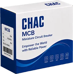
Packaging
Customization
Cartons, labels and manuals can be prepared for the approved order specification and destination market.

Electrical
Customization
Select from the published 6A–63A, 1P+N / 3P+N and B / C / D options; non-standard requests require technical evaluation.

Product
Appearance
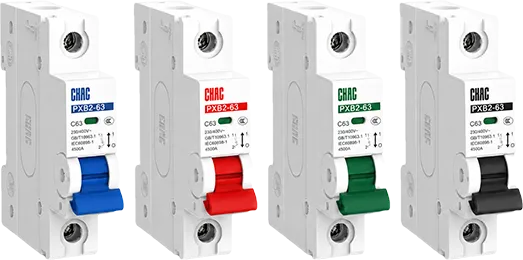
Appearance options can be reviewed subject to tooling, minimum order quantity, marking requirements and technical feasibility.

Certification
Support
Datasheets, drawings and verified certificate information are supplied for the applicable approved configuration.


Engineering
Development
Project support may include drawing review, sample evaluation, testing and production planning, subject to technical approval.

Download
PXB6 Series Miniature Circuit Breaker
Complete product overview for low-voltage electrical components and product selection reference.
Need Technical Documents?
Contact us for datasheets, certificates, drawings, selection guidance or OEM/ODM project support.
PXB6L-63 Product FAQ
What is the PXB6L-63 RCBO?
The PXB6L-63 combines overload and short-circuit protection with residual-current protection. Its verified range is 6A–63A with 1P+N / 3P+N configurations; the exact ordered option must match the circuit and local rules.
How does the PXB6L-63 RCBO work?
A thermal-magnetic mechanism responds to overload and short-circuit conditions, while the residual-current function monitors imbalance between conductors and trips when the applicable threshold is reached. It does not remove the need for correct earthing, circuit design or testing.
How is the PXB6L-63 RCBO different from an MCB or RCCB?
An MCB provides overcurrent protection but not residual-current protection. An RCCB provides residual-current protection but normally needs separate overcurrent protection. The PXB6L-63 combines both functions in one product, within its published ratings.
Can the PXB6L-63 RCBO be used as a circuit breaker?
It can provide the overcurrent and residual-current functions stated for the model, but only when 230/400V AC, 6A–63A, 6kA Ics and the residual-current requirements all suit the circuit. It should not be treated as a universal replacement for every breaker.
What are the selection limitations of the PXB6L-63 RCBO?
The principal checks are residual-current sensitivity (30 / 50 / 100 / 300mA), residual-current or construction type (Type AC / Type A; electronic construction), trip curve (B / C / D), pole arrangement (1P+N / 3P+N) and short-circuit data (6kA Ics). Board space, neutral handling, coordination and destination-market rules also have to be verified.
How should the PXB6L-63 RCBO be wired and tested?
Use only the diagram and terminal identification supplied for the exact ordered model. Confirm supply direction, protected neutral arrangement, conductor size, torque and isolation procedure, then perform the prescribed test-button and functional checks. Qualified personnel should complete the work under local rules.
Confirm the Right PXB6L-63 Configuration
Send the current rating, poles, trip curve, system voltage, expected fault level, destination market and quantity, plus residual-current sensitivity and type. CHAC will review the request against the published model range.