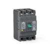
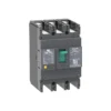
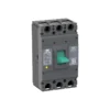
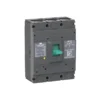
CQM7 Thermal-Magnetic MCCB Manufacturer with OEM Branding Options
Phần CQM7 Series Thermal-Magnetic Molded Case Circuit Breaker provides overload and short-circuit protection for low-voltage AC distribution systems, with a 16–800A range and AC 400/415V ratings. Panel builders and equipment manufacturers can select the frame, breaking capacity and accessories to suit their assemblies. For distributor orders or project procurement, share your required configuration and quantity with CHAC for review.
Product Overview
The CQM7 Series Thermal-Magnetic Molded Case Circuit Breaker covers a rated current range of 16A-800A. Its compact design combines overload and short-circuit protection with accessory options for low-voltage switchboards and equipment assemblies. For OEM projects and distribution orders, the CQM7 catalogue gives purchasing and engineering teams a common reference for confirming ratings, dimensions and accessories before ordering.
Applications
Typical applications include industrial power distribution, commercial buildings, infrastructure, switchboards and motor protection. Panel builders and electrical contractors should match the selected CQM7 configuration to the circuit design, enclosure space and protection requirements. Importers and distributors can use the frame and current options to define a product range for their market, with local requirements checked for each configuration.
Main Specifications
Rated Current: 16A-800A
Rated Operational Voltage: AC 400/415V
Rated Insulation Voltage: 800V
Rated Impulse Withstand Voltage: 8kV
Short-Circuit Breaking Capacity: Up to 50kA Icu at AC 400/415V, depending on frame and breaking-capacity designation
Trip Type: Thermal-Magnetic
Choose the Right CQM7 Frame for Your Project
Start with the circuit current and fault level, then compare the available CQM7 frames. The frame number identifies the frame rating; it does not mean that every breaker in that frame has the same rated current.
| CQM7 frame | Available rated currents (A) | Icu / Ics at AC 400/415 V (kA) |
|---|---|---|
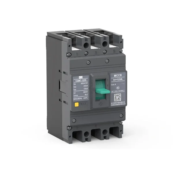
| CQM7-125 | 16, 20, 32, 40, 50, 63, 80, 100, 125 | C: 25 / 15; S: 30 / 20 |
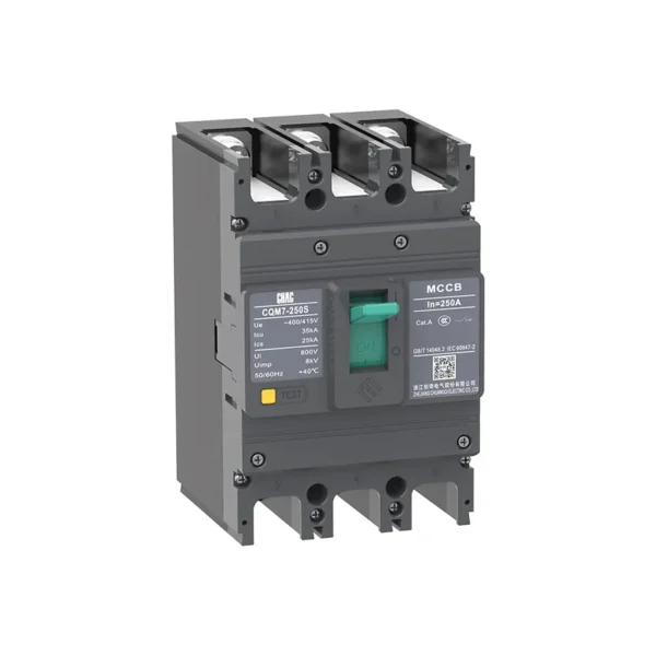
| CQM7-250 | 125, 140, 160, 180, 200, 225, 250 | C: 35 / 25; S: 40 / 30 |
| CQM7-400 | 250, 315, 350, 400 | S: 35 / 25; M: 50 / 35 |
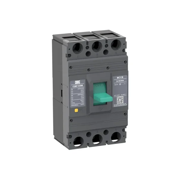
| CQM7-630 | 250, 315, 350, 400, 500, 630 | S: 35 / 25; M: 50 / 35 |
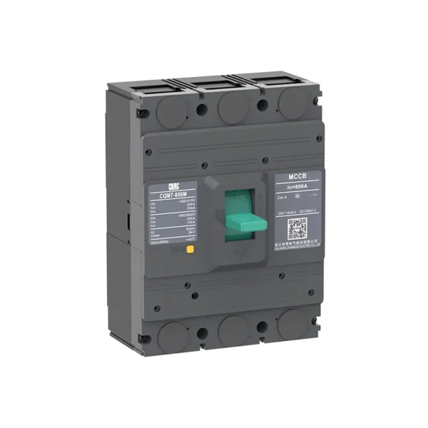
| CQM7-800 | 500, 630, 700, 800 | S: 35 / 25; M: 50 / 35 |
The ratings above are for the published 3-pole models. C, S and M identify the listed breaking-capacity options. Match the selected option to the installation fault level and required service performance. Where current ratings overlap between frames, also compare mounting dimensions, conductor connections and accessory requirements.
Selection Guide

| Product code | Extension Code | Shell frame grade | Breaking capacity | Operating method | Number of poles | ||||
| CQM7 | G | 125 | C | P | 4 | ||||
| Molded case circuit breaker | — : Thermal and magnetic protection are not adjustable G : Overload alarm without trip function |
C | S | M | H | P:Motorized operation Z:Tuning handle W:Direct operation |
125A:3P 250A:3P 400A:3P 630A:3P 800A:3P |
||
| 125 | 125 | 25/15 | 30/20 | / | / | ||||
| 250 | 250 | 35/25 | 40/30 | / | / | ||||
| 400 | 400 | / | 35/25 | 50/35 | / | ||||
| 630 | 630 | / | 35/25 | 50/35 | / | ||||
| 800 | 800 | / | 35/25 | 50/35 | / | ||||
| Trip Unit & Accessories | Rated current A | Function | 4P Option Code | Special code | |
| 300 | 125A | 2 | A | I | |
| The first digit indicates the type of detent 2:Instantaneous detent only 3:Duplicate detent Note:The last two digits are the accessory designator(see accessory table). |
125 | 16,20,32,40,50,63,80,100,125 | 1:For power distribution 2:For motor protection |
A:N-pole is unprotected and cannot be combined B:N-pole is unprotected and can be combined C:N-pole is protected and can be combined D:N-pole is protected and cannot be combined |
I: Overload alarm non trip function |
| 250 | 125,140,160,180,200,225,250 | ||||
| 400 | 250,315,350,400 | ||||
| 630 | 250,315,350,400,500,630 | ||||
| 800 | 500,630,700,800 | ||||
| Accessory Voltage | Motorized operating voltage | Cài đặt | Terminal Block Option | |||
| Q1 | D1 | Q | 2 | |||
| Undervoltage detent Q1:AC220V Q2:AC240V Q3:AC380V Q4:AC415V |
Shunt release F1:AC220V F2:AC380V F3:DC110V F4:DC24V |
Auxiliary alarm J1:AC125V J2:AC250V J3:DC125V J4:DC24V |
CD1 Electrical Operation D1:AC220V D2:AC230V D3:AC380V D4:AC400V |
CD2 Electrical Operation D5:AC230V D6:AC110V D7:DC220V D8:DC110 D9:AC110-240V D10:DC100-220V |
Q:Front of plate H:Rear of plate C:Inserted |
1:Noinstallation 2:Installation |
| Note:When motorized operation is selected,please refer to the external accessories for the two voltages applicable for motorized operation. | ||||||
Main Technical Parameters
| Model number | CQM7-125 | CQM7-250 | ||||
| Rated frame current Inm (A) | 125 | 250 | ||||
| Number of poles | 3 | 3 | ||||
| Rated current In (A) at 40℃, 50℃, 55℃ | 16, 20, 32, 40, 50, 63, 80, 100, 125 | 125, 140, 160, 180, 200, 225, 250 | ||||
| Rated operating voltage Ue (V), AC 50/60 Hz | 400/415 | 400/415 | ||||
| Rated insulation voltage Ui (V) | 800 | 800 | ||||
| Rated impulse withstand voltage Uimp (kV) | 8 | 8 | ||||
| Breaking capacity designation | C | S | C | S | ||
| Short-circuit breaking capacity Icu/Ics (kA) | AC 400/415 V | 25/15 | 30/20 | 35/25 | 40/30 | |
| Selectivity category | A | A | A | A | ||
| Number of operating cycles (cycle) | ON | 1000 | 1000 | |||
| OFF | 10000 | 10000 | ||||
| Trip mechanisms and protection types | Magnetic trip | Power distribution protection | ● | ● | ● | ● |
| Motor protection | ● | ● | ● | ● | ||
| Thermal-magnetic trip | Power distribution protection | ● | ● | ● | ● | |
| Motor protection | ● | ● | ● | ● | ||
| Accessories | Auxiliary contacts | ● | ● | ● | ● | |
| Alarm contacts | ● | ● | ● | ● | ||
| Shunt disconnect | ● | ● | ● | ● | ||
| Undervoltage detent | ● | ● | ● | ● | ||
| Manual operating mechanism | ● | ● | ● | ● | ||
| Motorized operating mechanism | ● | ● | ● | ● | ||
| Backplane wiring | ● | ● | ● | ● | ||
| Inserted | ● | ● | ● | ● | ||
| Coupling plate | ● | ● | ● | ● | ||
| Partition between phases | ● | ● | ● | ● | ||
| Derivative products | Dedicated for prepayment electric meters | ● | ● | ● | ● | |
| Overload alarm without trip | – | – | ● | ● | ||
| Overall dimensions (mm) (a-b-c-ca) | 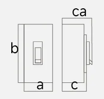 |
3 P | 77×131×65×82 | 105×165×68×95 | ||
Note:● for optional accessories; “-” for no optional accessories.
| Model number | CQM7-400 | CQM7-630 | CQM7-800 | |||||
| Rated current of frame level Inm(A) | 400 | 630 | 800 | |||||
| Number of poles | 3 | 3 | 3 | |||||
| Rated current In(A),at 40℃,50℃,55℃ | 250, 315, 350, 400 | 250, 315, 350, 400, 500, 630 | 500, 630, 700, 800 | |||||
| Rated operating voltage Ue(V),AC 50/60Hz | 400/415 | 400/415 | 400/415 | |||||
| Rated insulation voltage Ui (V) | 800 | 800 | 800 | |||||
| Rated impulse withstand voltage Uimp(KV) | 8 | 8 | 8 | |||||
| Breaking capacity designation | S | M | S | M | S | M | ||
| Short-circuit breaking capacity Icu/Ics(kA) | AC400/415V | 35/25 | 50/35 | 35/25 | 50/35 | 35/25 | 50/35 | |
| Selectivity category | A | A | A | A | A | A | ||
| Number of operating cycles (cycle) | ON | 1000 | 1000 | 500 | ||||
| OFF | 4000 | 4000 | 2500 | |||||
| Trip mechanisms and protection types |
Magnetic trip | Power distribution protection | ● | ● | ● | ● | ● | ● |
| Motor protection | ● | ● | ● | ● | ● | ● | ||
| Thermal-magnetic trip | Power distribution protection | ● | ● | ● | ● | ● | ● | |
| Motor protection | ● | ● | ● | ● | ● | ● | ||
| Accessory | Auxiliary contacts | ● | ● | ● | ● | ● | ● | |
| Alarm contacts | ● | ● | ● | ● | ● | ● | ||
| Shunt disconnect | ● | ● | ● | ● | ● | ● | ||
| Undervoltage detent | ● | ● | ● | ● | ● | ● | ||
| Manual operating mechanism | ● | ● | ● | ● | ● | ● | ||
| Motorized operating mechanism | ● | ● | ● | ● | ● | ● | ||
| Backplane wiring | ● | ● | ● | ● | ● | ● | ||
| Inserted | ● | ● | ● | ● | ● | ● | ||
| Coupling plate | ● | ● | ● | ● | ● | ● | ||
| Partition between phases | ● | ● | ● | ● | ● | ● | ||
| Derivative products | Dedicated for prepayment electric meters | ● | ● | ● | ● | ● | ● | |
| Overload alarm without trip | ● | ● | ● | ● | ● | ● | ||
| Overall dimensions (mm) (a-b-c-ca) |
|
3 P | 139×257×108×154 | 139×257×108×154 | 180×270×114×158 | |||
Note:● for optional accessories; “-” for no optional accessories.
Operating Characteristics
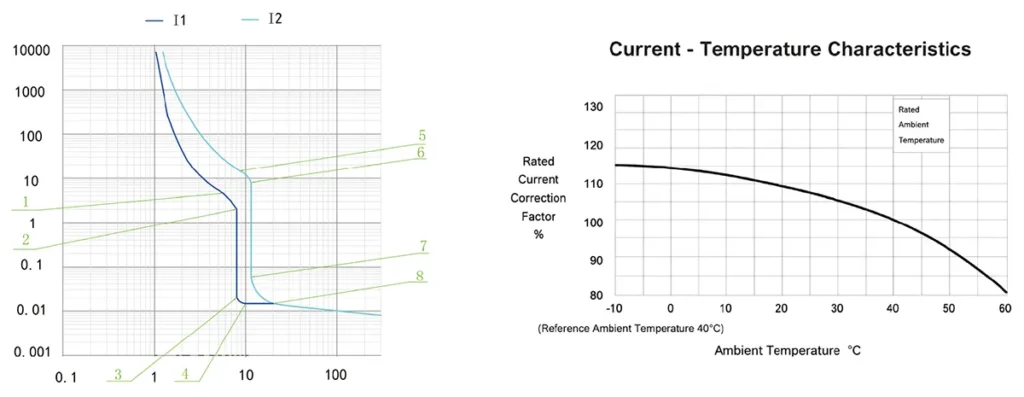
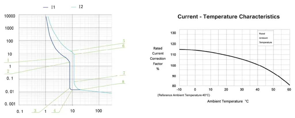
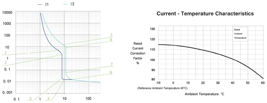
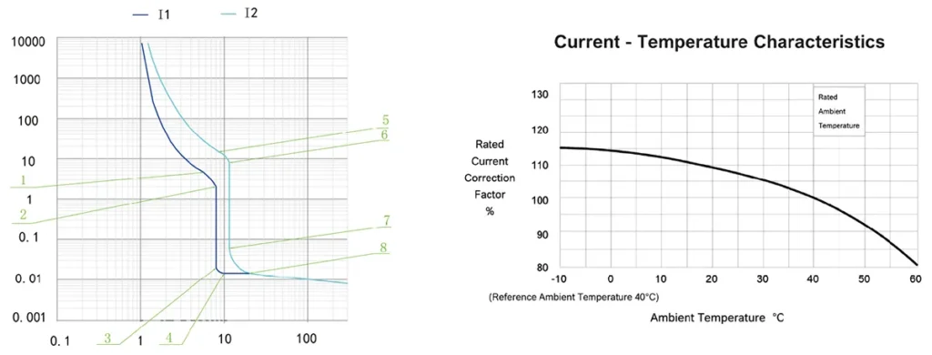
1.The inverse time operating characteristics of power distribution circuit breakers when all poles are energized simultaneously at anambientair temperature of +40℃(with no humidity compensation)are shown in the following table:
| Test current designation | Setting current multiple | Conventional time | Initial state |
| In≤63 63<In | |||
| Conventional non-tripping current | 1.05 | ≥1h ≥2h | Cool state |
| Conventional tripping current | 1.30 | <1h <2h | Hot state |
2.The inverse time action characteristics of circuit breakers for motor protection without humidity compensation when all poles are energized simultaneously at an ambient air temperature of +40℃ are shown in the following table:
| Test current designation | Setting current multiple | Conventional time | Initial state |
| In≤800 | |||
| Conventional non-tripping current | 1.0 | ≥2h | Cool state |
| Conventional tripping current | 1.2 | <2h | Hot state |
3.Action characteristics under short-circuit condition:The short-circuit current setting value of the instantaneous tripper of the circuit breaker for power distribution is 10In.
The short-circuit current setting value of the instantaneous tripper of the circuit breaker for motorprotection is 12In.
The accuracy of the short-circuit current setting value of the instantaneous tripper is 20% of the short-circuit current setting value.
Accessory List
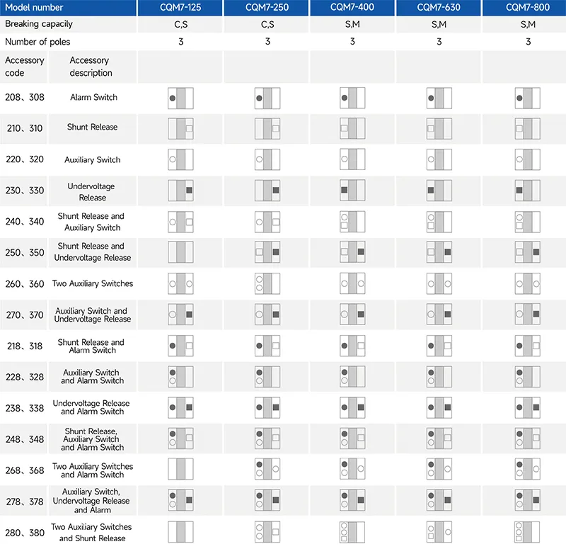
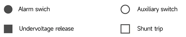
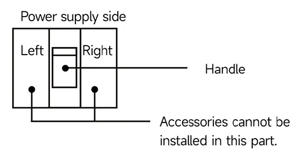
1.Our company can provide three new products for customers to choose from, namely the right-side auxiliary switch, the left-side shunt trip device, and the left-side undervoltage release device.
2.For the specifications of 220, 320, 240, 340, 270 and 370, the auxiliary switch can provide two pairs of switches. Please specify this when placing an order.
3.For the 250 and 350 specifications, the shunt trip device and undervoltage release for models 400 and above can only be installed on 3-pole circuit breakers.
CQM7-125 Operating Characteristic Curve
CQM7-250 Operating Characteristic Curve
CQM7-400 / 630 Operating Characteristic Curve
CQM7-800 Operating Characteristic Curve
Outline and Installation Dimensions(mm)
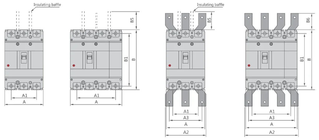
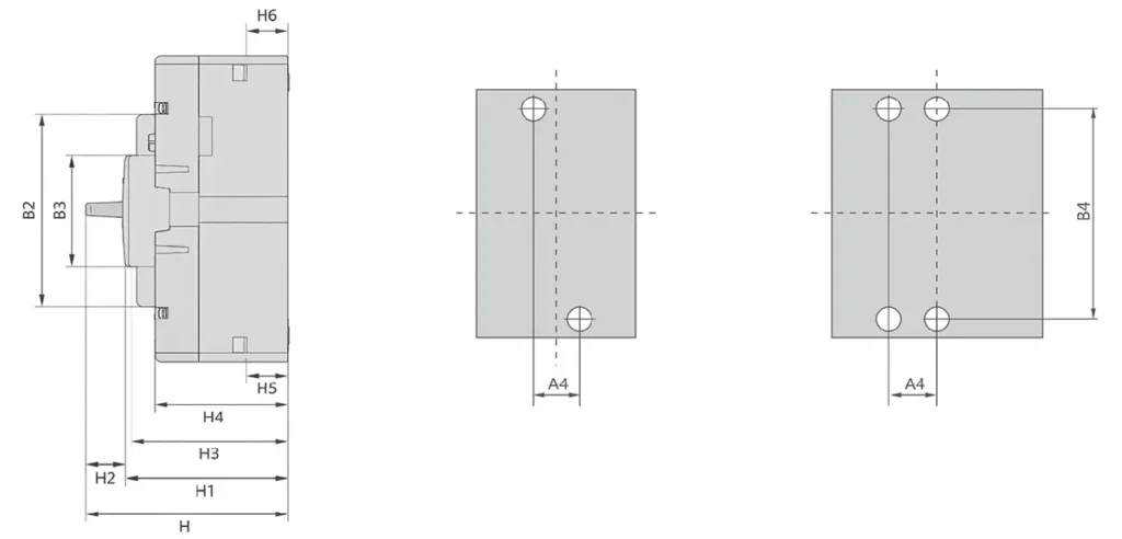
| Molded case Bộ ngắt mạch |
Overall dimension | Cài đặt dimensions |
Bolt | |||||||||||||||||||||
| A | A1 | A2 | A3 | B | B1 | B2 | B3 | B5 | B6 | H | H1 | H2 | H3 | H4 | H5 | H6 | A4 | B4 | ||||||
| 3P | 4P | 3P | 4P | 3P | 4P | 3P | 4P | |||||||||||||||||
| CQM7-125 | 77 | – | 50 | – | – | – | – | – | 131 | 116 | 90.2 | 45 | – | – | 82 | 68.3 | 3 | 65.3 | 56.5 | 25 | 25 | – | – | M6 |
| CQM7-250 | 105 | – | 70 | – | – | – | – | – | 165 | 144 | 101.2 | 60.8 | – | – | 95 | 73.1 | 6 | 68.1 | 61.4 | 22.3 | 23.1 | – | – | M8 |
| CQM7-400 | 139 | – | 88 | – | – | – | – | – | 257 | 224.5 | 150 | 97 | – | – | 154.2 | 110.5 | 4.5 | 108 | 99.5 | 35.2 | 36.5 | – | – | M10 |
| CQM7-630 | 136 | – | 88 | – | – | – | – | – | 257 | 224.5 | 150 | 97 | – | – | 154.2 | 110.5 | 4.5 | 108 | 99.5 | 35.2 | 36.5 | – | – | M10 |
| CQM7-800 | 180 | – | 116 | – | – | – | – | – | 270 | 235 | 150 | 96 | – | – | 158.2 | 116 | 5 | 114 | 103 | 43.5 | 44.8 | – | – | M12 |
Tại sao nên chọn CHAC
With 30+ years of manufacturing experience, 1100+ employees, 100M+ poles
annual capacity and 90% automated production, CHAC provides stable production capacity and strict
quality control for global OEM/ODM customers. Our in-house manufacturing system supports long-term
cooperation for electrical brands, importers and distributors.

30+
NĂM KINH NGHIỆM
Chuyên sản xuất thiết bị điện hạ thế

1100+
CÔNG NHÂN
Đội ngũ chuyên nghiệp đảm bảo chất lượng và giao hàng ổn định

100 triệu người
Sức chứa hàng năm của các cột
Năng lực sản xuất quy mô lớn để đáp ứng nhu cầu toàn cầu

90%
SẢN XUẤT TỰ ĐỘNG
Tự động hóa nâng cao cho hiệu quả cao và tính nhất quán
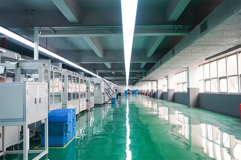
Dây chuyền lắp ráp tự động

Phòng thí nghiệm kiểm nghiệm
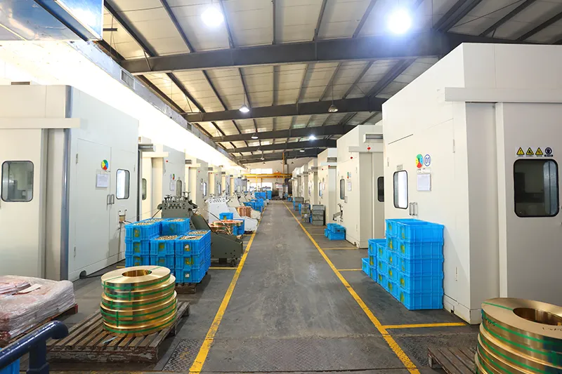
Xay và dập
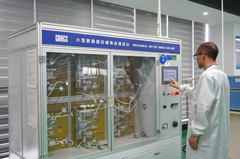
Kiểm tra chất lượng



Request the CQM7 technical and conformity documents required for your project. Company-level information and displayed marks do not establish approval of every CQM7 configuration in every market.
Chúng tôi có thể tùy chỉnh những gì?
For electrical brands, equipment manufacturers and distributors sourcing CQM7 MCCBs, start with the frame, rated current within the published 16–800 A range, protection duty and catalogue-listed accessories. CHAC can review private-label marking, packaging and technical-document requirements for the agreed configuration. Include your destination market and order quantity in the enquiry; housing, internal or electrical changes require engineering confirmation.

Enclosure
Design
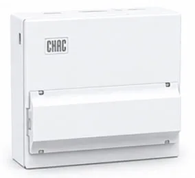
Check the CQM7 frame dimensions, mounting arrangement and clearances for your panel. Housing changes require engineering approval.

Internal
Configuration
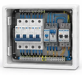
Select the required trip configuration and catalogue-listed accessory combinations for the ordered CQM7 frame.

Branding &
Logo
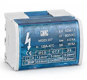
For private-label orders, review logo, nameplate and label artwork while retaining the required CQM7 identification and electrical markings.

Gói bao bì
Design
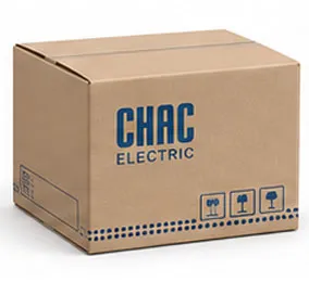
Discuss unit cartons, shipping cartons, labels and manuals for your distribution channel, with packaging requirements agreed before the order is confirmed.

Điện
Configuration
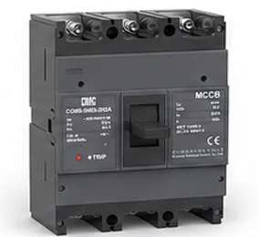
Confirm rated current, AC 400/415 V duty and breaking-capacity designation. Specify accessory control voltages separately.

Chứng nhận
Hỗ trợ
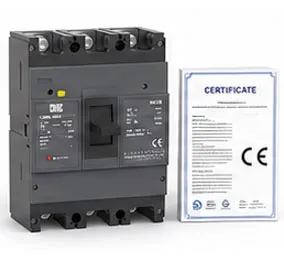
Request the technical documents needed for the exact CQM7 configuration and destination market. Verify approvals by model and scope.
What to Confirm Before Ordering CQM7 MCCBs
A clear specification helps panel builders, OEM purchasing teams and distributors compare quotations for the same product. Use these four checks to define the technical and commercial scope of your enquiry.
Define the electrical configuration
List the CQM7 frame, rated current, AC system voltage, required Icu/Ics, poles and distribution or motor-protection duty. Include the selected trip type and accessories.
Attach the relevant specification or bill of materials so the quotation identifies the intended configuration.
Break down the quantity by model
For project or distributor orders, state the quantity for each configuration. Separate any sample request from the main order and provide your requested delivery schedule.
Ask CHAC to confirm availability and lead time for the agreed configuration and quantity.
Agree the branding and packaging scope
For OEM branding, provide logo artwork, proposed nameplate details and label requirements. Specify unit and shipping cartons, manuals and any distributor packaging needs.
Review the proposed artwork and packaging specification before approving the order.
Identify the documents your market requires
State the destination market and request the applicable datasheet, dimensional drawing, installation instructions and conformity documents for the exact model.
Check document scope against the ordered configuration; company-level certificates do not establish every product approval.
Tải xuống
CQM7 Product Catalogue
CQM7 AC molded case circuit breaker catalogue with the 16–800 A selection guide, technical ratings, accessory options, operating curves and installation dimensions.
Need Technical Documents?
Contact us for datasheets, certificates, drawings, selection guidance or OEM/ODM project support.
CQM7 Product FAQ
What is the CQM7 molded case circuit breaker used for?
The CQM7 provides overload and short-circuit protection for low-voltage distribution circuits. Its published applications include industrial power distribution, commercial buildings, infrastructure, switchboards and motor protection. Choose the distribution or motor-protection version to match the circuit and its coordination requirements.
What is the rated operating voltage of the CQM7?
The CQM7 technical tables specify AC 400/415 V at 50/60 Hz. The 800 V insulation rating and 8 kV impulse withstand rating describe different characteristics; neither raises the permitted operating voltage. Use the operating-voltage and breaking-capacity ratings for the exact model being ordered.
How do I choose the CQM7 frame size and rated current?
The series covers 16–800 A across the CQM7-125, -250, -400, -630 and -800 frames. The frame rating is not the same as the fitted breaker’s rated current. Start with the design load and conductor protection requirements, then select an available current rating in the appropriate frame. Check ambient temperature, enclosure conditions and protection coordination before ordering.
What is the difference between Icu and Ics on a CQM7 MCCB?
Icu is the rated ultimate short-circuit breaking capacity; Ics is the rated service short-circuit breaking capacity. At AC 400/415 V, the CQM7 tables list Icu/Ics pairs of 25/15 or 30/20 kA for the 125 frame, 35/25 or 40/30 kA for the 250 frame, and 35/25 or 50/35 kA for the 400, 630 and 800 frames. Check the exact breaking-capacity designation against the installation’s fault level and service requirements. The maximum 50 kA Icu does not apply to every model.
Which CQM7 pole configurations are shown in the technical tables?
The published main technical tables and dimensional drawings list 3-pole models for the CQM7-125, -250, -400, -630 and -800 frames. Although the ordering guide also contains neutral-pole option codes, do not assume that every frame is available in a 4-pole version. Request the exact configuration and its applicable drawing before specifying a neutral pole.
What should be checked before installing and commissioning a CQM7?
A qualified installer should check the exact model, rated current, breaking capacity, mounting dimensions, conductor connections, terminal torque and required clearances against the installation instructions. Confirm accessory control voltages and complete the specified functional checks before energising. Use the drawing for the ordered frame rather than another CQM7 size.
How does a thermal-magnetic MCCB trip?
In a thermal-magnetic MCCB, the thermal element responds to a sustained overload, while the magnetic element responds to a high short-circuit current. The CQM7 catalogue distinguishes thermal-magnetic and magnetic-only configurations, as well as distribution and motor-protection duties. Specify the required protection type; a magnetic-only version does not provide the same overload protection as a thermal-magnetic version.
Are the CQM7 thermal and magnetic trip settings adjustable?
The standard thermal-magnetic configuration in the CQM7 ordering guide is described as having non-adjustable thermal and magnetic protection. Do not assume that all MCCBs have adjustable settings. If the project needs adjustable protection, provide the required setting ranges and coordination study so a suitable configuration or product can be evaluated.
When should I choose an MCCB instead of an MCB?
Evaluate an MCCB when the circuit requires a current range, breaking capacity, connection arrangement or control accessory that the proposed MCB does not provide. The CQM7 family extends to 800 A and offers frame-specific accessory options. Where ratings overlap, compare the exact devices and their coordination, dimensions and installation requirements rather than choosing by product category alone.
Does a CQM7 MCCB also provide earth-leakage protection?
The standard CQM7 described here provides overload and short-circuit protection. These functions do not establish residual-current or earth-leakage protection. If the project requires leakage protection, specify that function separately and confirm the suitable device or coordinated assembly. A shunt release alone does not detect leakage current.
Can the AC-rated CQM7 be used in a DC or photovoltaic circuit?
Do not apply the AC 400/415 V rating to a DC circuit. DC interruption requires a declared DC voltage, pole arrangement, current direction and breaking duty for the exact model. The CQM7 AC tables on this page do not establish those ratings. For PV or battery circuits, select a product with documented ratings for the intended DC application.
What is the difference between a shunt trip and an undervoltage release?
A shunt trip opens the breaker when it receives the specified external control signal. An undervoltage release responds when its control supply falls below its specified operating conditions and may prevent closing without adequate supply. The CQM7 catalogue lists both accessory types. Confirm the frame, accessory combination, AC or DC coil voltage and wiring diagram before ordering; the two functions are not interchangeable.
Confirm the Right CQM7 Configuration
Planning a panel-building project, distributor order or OEM supply enquiry? Send the CQM7 frame, rated current, AC system voltage, fault level, protection duty, accessories and quantity. Include the destination market and any branding or packaging requirements so CHAC can review the configuration and quotation scope.