Một kỹ thuật viên ước tính độ sụt áp trên một đường cáp 100-foot và thu được kết quả đáng an tâm. Mạch hai dây đã lắp đặt cho thấy độ sụt áp do điện trở lớn hơn khoảng gấp đôi so với dự đoán, vì phép tính chỉ tính đến dây dẫn đi mà bỏ qua dây dẫn về. Sai sót mang tính minh họa này rất phổ biến khi chiều dài tuyến và chiều dài dây dẫn bị xem là cùng một đại lượng.
Tóm tắt: Danh nghĩa điện trở của dây AWG 12 được làm từ đồng có điện trở khoảng 1.588 Ω trên mỗi 1,000 feet ở 20°C, hoặc 5.20864 Ω/km. Hãy nêu rõ vật liệu và nhiệt độ, tính toàn bộ đường dẫn dòng điện, và phân biệt điện trở của dây dẫn với điện trở của các mối nối cũng như tổng trở xoay chiều.
Điện trở của dây đồng AWG loại 12 ở 20°C là bao nhiêu?
Điện trở phụ thuộc vào điện trở suất, chiều dài và diện tích mặt cắt ngang của vật liệu dẫn điện: R = ρL/A. Giá trị điện trở theo tiêu chuẩn AWG thường được sử dụng giả định một loại vật liệu dẫn điện cụ thể và một nhiệt độ tham chiếu nhất định. Chỉ riêng ký hiệu cỡ dây không đủ để xác định điện trở khi vật liệu hoặc cấu tạo khác biệt.
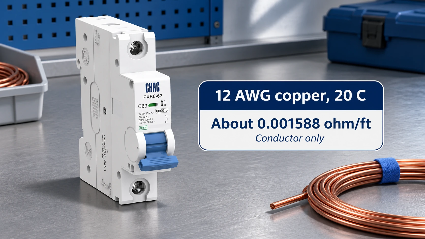
Bảng kích thước dây dẫn của PowerStream cho biết khoảng 1.588 Ω trên mỗi 1,000 feet đối với dây đồng cỡ 12 AWG. Chia cho 1,000 ta được 0.001588 Ω trên mỗi foot. Quy đổi theo cùng tài liệu tham khảo, ta có khoảng 0.00520864 Ω trên mỗi mét. Đây là các giá trị tham chiếu danh nghĩa, không phải là giá trị tối đa được đảm bảo cho mọi cáp hoàn chỉnh.
| Tham chiếu đồng AWG tại 20°C ở 12 | Điện trở xấp xỉ | Diễn giải |
|---|---|---|
| 1 chân của một dây dẫn | 0.001588 Ω | 1.588 miliôm |
| 100 feet của một dây dẫn | 0.1588 Ω | Không bao gồm dây dẫn trở về |
| 1,000 feet của một dây dẫn | 1.588 Ω | Cơ sở bảng tham chiếu chung |
| 1 mét của một dây dẫn | 0.00520864 Ω | 5.20864 miliôm |
| 1 kilômét của một dây dẫn | 5.20864 Ω | Cùng một tham chiếu được biểu diễn bằng đơn vị đo lường |
Các cột diện tích và điện trở trong bảng AWG trả lời những câu hỏi khác nhau. Diện tích giúp mô tả kích thước của dây dẫn; điện trở hỗ trợ tính toán sụt áp hoặc tổn thất điện năng. Tuy nhiên, chỉ riêng mỗi yếu tố này không đủ để xác định dòng điện cho phép trong một mạch điện đã được lắp đặt.
Đối với công tác mua sắm, khi có sẵn, hãy sử dụng giá trị điện trở tối đa của dây dẫn một chiều do nhà sản xuất cáp công bố. Giá trị danh định theo bảng kỹ thuật có thể hữu ích cho mục đích ước tính, nhưng giới hạn nghiệm thu theo hợp đồng cần nêu rõ tiêu chuẩn sản phẩm, nhiệt độ thử nghiệm, cơ sở chiều dài và cấu tạo của sản phẩm.
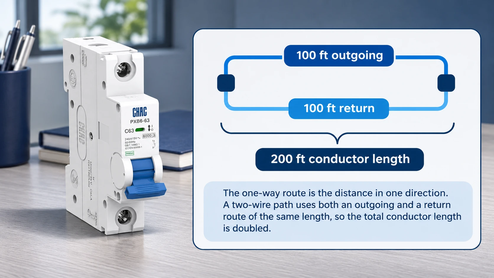
Calculate voltage drop using both outgoing and return conductor lengths
For a simple two-wire DC circuit, current travels to the load and returns through another conductor. If the route is 100 feet and both conductors have the same size and length, the resistive path is 200 feet. Its nominal resistance at 20°C is 200 × 0.001588 = 0.3176 Ω.
At a hypothetical 20 A load, Vdrop = I × R = 20 × 0.3176 = 6.352 V. Relative to 120 V, that is approximately 5.29%; relative to 240 V, it is approximately 2.65%. These percentages compare the same resistive drop with two different supply voltages; they do not approve a particular circuit design.
The example is exact for its stated resistive DC model and is a useful approximation for an AC circuit where reactance and power-factor effects are negligible. Other AC arrangements need the appropriate impedance and phase relationships. In particular, do not apply the simple two-wire multiplier indiscriminately to a balanced three-phase calculation.
| Illustrative two-wire circuit | 20°C reference | 75°C estimate |
|---|---|---|
| Chiều dài tuyến một chiều | 100 ft | 100 ft |
| Total outgoing and return length | 200 ft | 200 ft |
| Resistance per 1,000 ft | 1.588 Ω | About 1.931 Ω |
| Loop resistance | 0.3176 Ω | About 0.3862 Ω |
| Current used for the calculation | 20 A | 20 A |
| Sụt áp điện trở | 6.352 V | About 7.725 V |
The 20 A value is chosen only to demonstrate arithmetic. Permissible loading depends on conductor material, insulation, installation conditions, terminals and applicable rules. A successful voltage-drop calculation cannot replace the separate ampacity and protection checks.
How conductor temperature changes 12 AWG copper resistance
Conductor temperature matters because copper resistance rises as temperature increases. A practical linear approximation around the reference range is RT = R20[1 + α(T − 20)], using a copper coefficient of approximately 0.00393 per °C at 20°C.
At 75°C, the factor is 1 + 0.00393 × 55 = 1.21615. Multiplying 1.588 Ω per 1,000 feet by that factor gives approximately 1.931 Ω per 1,000 feet. The corresponding 200-foot loop is approximately 0.3862 Ω, producing about 7.725 V drop at the illustrative 20 A.
This is a temperature-correction example, not a prediction that the conductor will operate at 75°C. Actual operating temperature depends on load, ambient conditions, heat dissipation and installation. An insulation temperature marking is a limit under specified conditions, not an automatic estimate of running temperature.
Keep the reference conditions with the result. Comparing a manufacturer’s resistance at 20°C with an operating measurement on a warm conductor can suggest a defect where none exists. Equally, unexplained excess resistance should not be dismissed as temperature without checking the actual conditions.
How material, stranding and connections affect total circuit resistance
Aluminum has higher resistivity than copper. Using illustrative material values of 2.65 × 10⁻⁸ Ωm for aluminum and 1.724 × 10⁻⁸ Ωm for copper gives a ratio of about 1.54 for equal length and area at the stated reference conditions. Actual alloys and product specifications must be checked.
That ratio is a material comparison, not permission to substitute aluminum wire in a copper-only terminal. Conductor approval, connection method and installation rules remain separate. Do not infer compatibility from gauge size or a resistance calculation.
Stranded and solid conductors of the same nominal gauge have similar intended metallic area, but exact resistance can differ with strand geometry, lay length and manufacturing limits. For long runs or acceptance testing, use the exact product’s resistance data rather than assuming every construction matches a single table value.
Connections add resistance to the circuit. A poor termination can create a localized hot spot that is not represented by the uniform conductor model. Longer cable resistance and defective connection resistance may produce similar total voltage loss while requiring very different corrective action.
At low resistance values, measurement method matters. Test-lead and contact resistance can be significant compared with the sample. Suitable four-wire measurement can separate lead effects for an appropriate de-energized test, while temperature and sample length must still be recorded.
Check circuit conditions before using resistance to calculate voltage drop
For AC circuits, resistance is only part of impedance. Frequency, conductor arrangement and load power factor can affect the calculated drop. Use the relevant method for the circuit, and check whether a calculator expects one-way route length or total conductor length before entering the number.
Phần voltage-drop calculator can support an initial check when its assumptions match the installation. Keep the material, temperature basis, load current, voltage and length definition with the output so another reviewer can reproduce the result.
When selecting a CHAC PXB6-63 cầu dao tự động loại nhỏ, confirm conductor and terminal requirements independently of voltage drop. The resistance values in this article do not establish an approved conductor type, current setting or protective arrangement for a particular model.
A useful purchase or design record includes the exact wire construction, manufacturer’s maximum resistance, expected operating conditions and permitted voltage drop. This makes a proposed cable substitution reviewable. It also prevents a nominally equal gauge from being accepted without checking material and installation differences.
Common questions about 12 AWG resistance and voltage drop
What is the resistance of 12 AWG copper wire per foot at 20°C?
The nominal reference is approximately 0.001588 Ω per foot, or 1.588 milliohms per foot. It applies to one conductor length. Use the manufacturer’s specified value for product acceptance.
What is the resistance of 12 AWG copper wire per meter?
It is approximately 0.00520864 Ω per meter at 20°C using the stated reference. That is about 5.209 milliohms per meter. Material and temperature must remain part of the description.
What is the resistance of a 100-foot length of 12 AWG copper wire?
One 100-foot conductor is approximately 0.1588 Ω at 20°C. A 100-foot two-wire route with an equal return conductor has approximately 0.3176 Ω of conductor-loop resistance. Connections add separately.
How does temperature change the resistance of 12 AWG wire?
Copper resistance increases with temperature. Using a coefficient of 0.00393 per °C gives approximately 21.6% higher resistance at 75°C than at 20°C. The actual conductor temperature must be assessed separately.
Does stranded 12 AWG wire have the same resistance as solid wire?
The values are generally comparable for the same material and nominal size, but are not necessarily identical. Strand lay and manufacturing specifications affect the result. Use the exact product’s maximum DC resistance where accuracy matters.
How does 12 AWG aluminum wire resistance compare with copper?
Aluminum has higher resistance for the same area and length. The illustrative resistivity values used here give about 1.54 times the copper value. This comparison does not establish interchangeability or terminal approval.
How do you calculate voltage drop using the round-trip resistance of 12 AWG wire?
For the simple two-wire resistive case, multiply resistance per unit length by the outgoing plus return length, then multiply by current. A 200-foot loop at 20°C is about 0.3176 Ω, giving 6.352 V drop at 20 A. Use the appropriate AC method where reactance or phase relationships matter.
Tham khảo
- PowerStream: AWG conductor resistance reference
- Engineering ToolBox: material resistivity and temperature coefficients
- Engineering ToolBox: copper wire properties
A resistance value becomes useful when its material, temperature and length are clear. Discuss your breaker application with CHAC using the conductor specification and completed circuit calculation.