
A breaker described as electronic can still be the wrong choice if its trip functions or settings do not match the feeder. A thermal-magnetic device can also be appropriate for a straightforward circuit, provided its response and fault duty meet the design. The important comparison is not old versus new technology, but the protection characteristics the installation actually needs. This guide separates the trip approach from frame size, breaking capacity, monitoring and selectivity. It also explains why adjustable settings need a documented protection study, rather than being treated as spare flexibility that can be changed whenever a load trips.
The short answer is to choose a thermal-magnetic MCCB when its documented overload and instantaneous response meets the circuit, and evaluate an electronic MCCB when specific adjustable functions or additional information are needed. Electronic does not automatically mean metering, communications, ground-fault protection or complete selectivity. IEC 60947-2 characteristics discussed in Schneider’s Electrical Installation Guide include operating voltage, current, trip settings and breaking duty; each remains a separate selection item. Confirm the actual frame and trip-unit variant, prospective fault current and upstream/downstream combination before approving either approach.
How do the trip approaches differ?
A thermal-magnetic unit uses thermal and magnetic responses for its overcurrent functions. An electronic unit evaluates sensed current using its documented logic. Both must be reviewed against actual time-current characteristics, tolerances and installed conditions.
| Decision | Thermal-magnetic approach | Electronic approach |
|---|---|---|
| Overload response | Specified thermal characteristic | Documented long-time function |
| Short-circuit response | Magnetic characteristic, fixed or adjustable by model | Supported short-time and instantaneous functions |
| Adjustment | Use the actual available range | Confirm functions, ranges and dependencies |
| Monitoring | Check accessory options | Not inherent in the technology name |
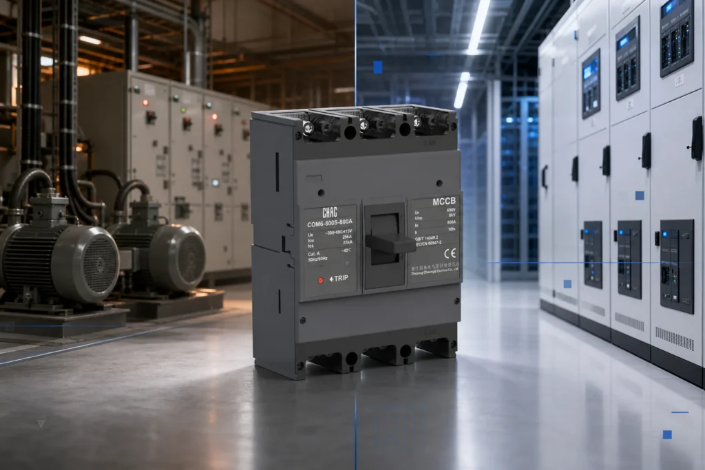
This is a function-based comparison of published guidance checked October 10, 2026. It is not a supplier ranking, test result or assertion that the two pictured families are interchangeable.
When is thermal-magnetic protection sufficient?
Consider it where the chosen curve protects the conductor and accommodates the intended load without needing unsupported adjustment. Motor and transformer inrush should be part of the assessment; normal starting current must not be mistaken for a sustained overload or fault.
Schneider’s thermal-magnetic trip explanation states that short-circuit operation has no intentional delay, while response below the instantaneous threshold allows momentary surges subject to the protective characteristic. It also notes that some instantaneous settings are adjustable. Therefore, thermal-magnetic does not universally mean every setting is fixed.
Which electronic functions does the project need?
Name the required functions rather than asking for an electronic breaker in general. Common labels L, S, I and G refer to long-time, short-time, instantaneous and ground-fault functions, where actually supported. Obtain threshold ranges, delays, tolerances and any dependencies for the ordered unit.
Check whether auxiliary power is required for displays, communications or other features separately from the protective functions. Do not assume loss of a display means loss of protection, or that protection remains available without a documented supply basis. Ground-fault protection in an MCCB is not automatically equivalent to the high-sensitivity residual-current protection required for another circuit.
Why do trip settings not establish breaking capacity?
Frame size, rated current, overload setting and fault-interruption duty are different quantities. A larger frame or a higher magnetic threshold does not make a breaker suitable for a higher prospective fault current.
Phần Electrical Installation Guide’s breaker-characteristics chapter explains Icu and Ics under IEC 60947-2. Check the declared values at the actual operating voltage and configuration. Service-continuity objectives and post-fault assessment require more than copying the largest kA number in a product-family summary.
Does an adjustable unit guarantee selectivity?
No. Protection selectivity means the relevant downstream protective device clears a fault while the other devices remain unaffected under the established conditions. A partial-selectivity limit is not a guarantee above that fault current.
Schneider’s coordination guidance distinguishes selectivity from cascading or backup protection. Cascading can involve the upstream device helping the downstream device interrupt a fault; it does not independently guarantee continuity of upstream supply. Manufacturer-tested combinations and their limits govern the claim.
| Evidence | What it must establish |
|---|---|
| Time-current curves | Relevant response ranges and tolerances |
| Selectivity tables | Exact device pair, settings, voltage and limit |
| Backup-protection tables | Tested combination and conditions |
| Source conditions | Fault levels for normal and alternative supplies |
Increasing an upstream delay needs a design review of conductor and equipment protection. Do not change settings solely to make curves look separated or to avoid an unexplained trip. High-current behavior cannot always be established from curve separation alone.
How should CQM6 and CQM6E be reviewed?
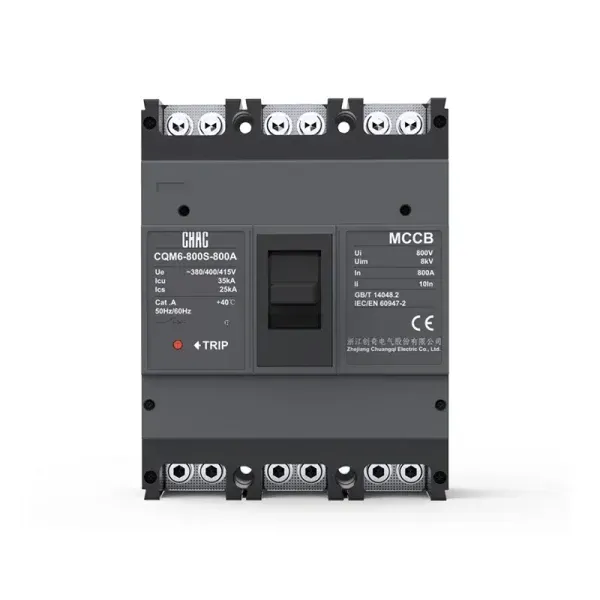
CHAC’s Bộ ngắt mạch dạng đúc record gives the CQM6 product route. The electronic adjustable MCCB page identifies CQM6E and lists adjustable protection in its published configuration. Request the exact frame/trip-unit data instead of applying the family’s largest current or breaking rating to every model.
The broader Dòng sản phẩm MCCB helps locate alternatives. Neither a family description nor an accessory photograph establishes selectivity, communication capability or approved interchangeability.
What must be recorded before the feeder is released?
Retain the approved single-line diagram, exact installed variants, study inputs, settings and coordinated-device references. Include ambient/enclosure conditions and alternative-source operation where relevant. Authorized commissioning should verify the installed settings against the approved record and use the manufacturer’s test procedures.
Record who may change the settings and when the study must be reviewed. Load additions, a changed transformer or generator operation can invalidate assumptions that were correct at initial commissioning.
Các câu hỏi thường gặp
Does electronic mean every protection function is adjustable?
No. Confirm the exact unit’s supported functions and ranges; options can vary within one family.
Can a larger ampere rating compensate for insufficient breaking capacity?
No. Carrying current and fault-interruption duty are separate selection requirements.
Does an electronic trip unit need a separate supply?
It depends on the unit and function. Obtain the documented power requirements for protection, display and communications separately.
Are cascading and selectivity the same?
No. Backup protection and continuity of unaffected circuits have different objectives and require separate verified combination data.
Can settings remain unchanged when a generator is added?
Only after reviewing the alternate-source fault and protection conditions. Do not assume the original study covers a new source.
Can a thermal-magnetic breaker be replaced by an electronic one with the same frame?
Not on frame appearance alone. Verify the approved mechanical interface, ratings, accessories, protection study and exact replacement documentation.
Tham khảo
- Schneider Electric: how a thermal-magnetic trip unit works.
- Schneider Electric Electrical Installation Guide: fundamental circuit-breaker characteristics, edited August 2026.
- Schneider Electric Electrical Installation Guide: coordination between circuit-breakers, edited August 2026.
Choose a trip approach only after establishing the feeder’s protection requirements. Verify voltage and fault duty, match the response to the load and conductors, and then confirm any adjustment needed for the coordinated installation. Monitoring and communication features should be evaluated separately, with no assumption that electronic means fully equipped. Keep selectivity, backup protection and breaking capacity distinct, and retain a settings record that can be reviewed when the system changes. CHAC’s CQM6 and CQM6E records can support a component discussion; the study and exact model data control approval. Contact CHAC with the single-line diagram and required protection functions.
Để tham khảo các lựa chọn liên quan, hãy xem Thermal Magnetic vs Electronic MCCB.
Continue with this related guide: Voltage Protector Keeps Tripping How.