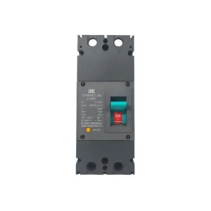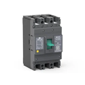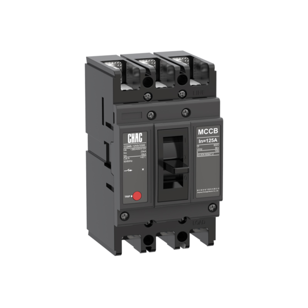
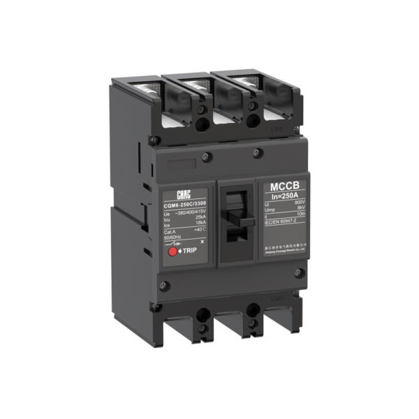
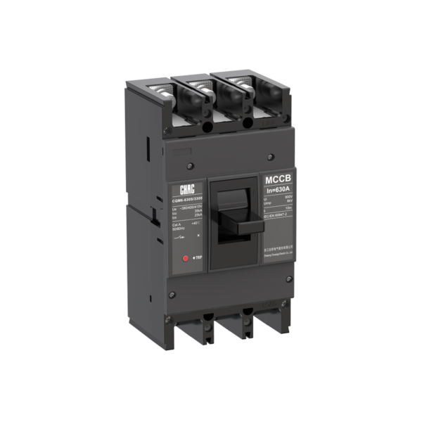
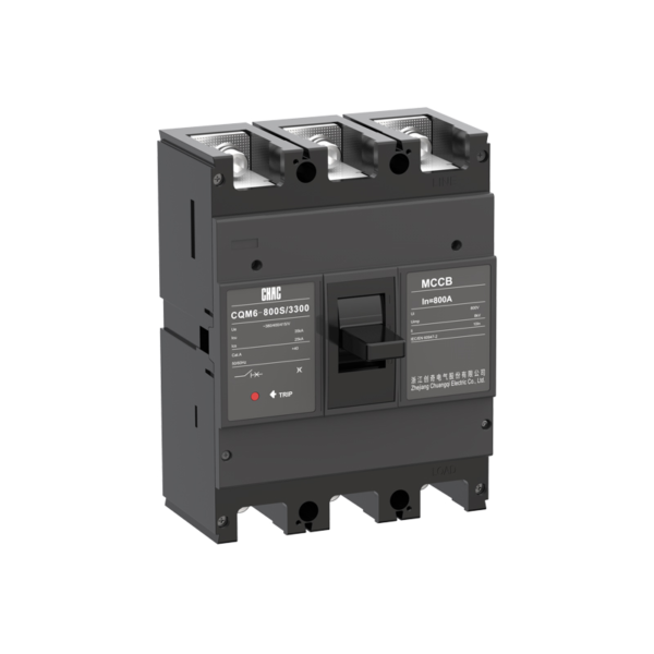
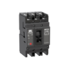
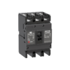
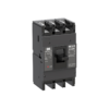
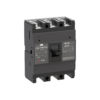
CQM6 Standard Molded Case Circuit Breaker (MCCB) Nhà sản xuất OEM
Phần CQM6 MCCB cung cấp bảo vệ quá tải và ngắn mạch trong phạm vi 16–1600A đã được công bố. Việc lập đặc tính kỹ thuật cần tuân theo điện áp hệ thống, phụ tải, sự phối hợp giữa dây dẫn, dòng sự cố dự kiến và các quy tắc áp dụng—chứ không chỉ dựa vào giá trị ampe đơn thuần.
Giới thiệu sản phẩm
CQM6 is a mccb breaker for AC distribution and protection applications. Its published range covers 16–1600A with 2P / 3P / 4P, depending on frame; CQM6-1600: 3P options. Selection depends on the complete power-system design, including fault level, coordination, conductor ampacity, enclosure conditions and local rules.
Thông số kỹ thuật sản phẩm được cung cấp có tham chiếu đến IEC/EN 60947-1, IEC/EN 60947-2, IEC/EN 60947-3 và IEC/EN 60947-4, cùng với GB/T 14048.1, .2, .3 và .4. Các tài liệu tham khảo tiêu chuẩn này, nếu chỉ riêng chúng, không đủ để xác nhận chứng nhận cho một đơn hàng cụ thể.
Tính năng chính
Các ứng dụng điển hình
Typical applications include commercial, industrial and infrastructure distribution or motor circuits. These are evaluation contexts rather than universal approvals. Confirm the exact frame, voltage, breaking duty, trip unit, accessories and installation method before specification.
Hướng dẫn đăng ký và tuyển chọn
Use the verified CQM6 values below to create a shortlist, then validate the complete circuit. An MCCB rating does not replace conductor calculations, fault-current analysis, coordination review or local installation requirements.
| Điểm lựa chọn | CQM6 reference | Những gì dự án phải xác nhận |
|---|---|---|
| Độ dòng định mức | 16–1600A | Dòng điện thiết kế, dòng điện định mức của dây dẫn, phương pháp lắp đặt, nhiệt độ và nhóm dây |
| Điện áp | AC 400/415V; CQM6-1600 cũng liệt kê các cấu hình 660/690V | Hệ thống cung cấp và định mức thiết bị |
| Người Ba Lan | 2P / 3P / 4P, tùy thuộc vào khung hình; CQM6-1600: 3P | Đường dây mang điện và xử lý dây trung tính |
| Chuyến đi / sự bảo vệ | cầu dao bảo vệ nhiệt từ | Hồ sơ phụ tải, phản ứng sự cố và phối hợp |
| Khả năng phá vỡ | Các lớp C/S/M/H/L, với Icu lên đến 100kA cho các cấu hình CQM6-1600 660/690V được liệt kê; vui lòng xác minh khung và điện áp chính xác. | Dòng điện ngắn mạch dự kiến tại điểm lắp đặt |
Fixed vs Adjustable Protection
A fixed thermal-magnetic device can suit a stable design, while an adjustable trip unit may help coordination when the project study requires field settings.
Trip Coordination
Compare MCCB Options →
MCCB vs MCB
An MCCB is normally evaluated for higher current, fault duty or accessory flexibility; an MCB may be more suitable for compact final circuits.
Current & Fault Duty
Compare MCCB and MCB →
Icu vs Ics
The saved data for CQM6 lists C/S/M/H/L classes, with Icu up to 100kA for the listed CQM6-1600 660/690V configurations; verify the exact frame and voltage. Match the declared duty to the prospective short-circuit current and continuity objective.
Short-Circuit Study
Review Technical Support →
Pole and Neutral Arrangement
Published pole options are 2P / 3P / 4P, depending on frame; CQM6-1600: 3P. Confirm which conductors must be switched, protected and isolated together.
System Arrangement
View MCCB Range →
Hướng dẫn đặt hàng
- State the exact model: CQM6.
- Provide frame and rated current within the published range: 16–1600A.
- Confirm poles: 2P / 3P / 4P, depending on frame; CQM6-1600: 3P.
- Specify the trip unit or protection function: thermal-magnetic trip.
- Provide system voltage, frequency, application, expected fault level, destination market and quantity.
- List required accessories, terminals, documents and any approved OEM/ODM marking or packaging requirements.
Kiểm tra lắp đặt và phối hợp
- Use the exact model drawing and instructions; do not infer terminal positions, supply direction or accessory compatibility from another MCCB.
- Verify conductor material and cross-section against the circuit calculation, terminal data, temperature and grouping.
- Confirm Icu/Ics or DC fault duty, upstream/downstream coordination, enclosure conditions, altitude and clearances.
- Installation, isolation, testing and maintenance must be performed by qualified personnel under applicable rules.
Selection Guide

| Product code ① | Extension Code ② | Shell frame grade ③ | Breaking capacity ④ | Operating method ⑤ | Number of poles ⑥ | |||||
|---|---|---|---|---|---|---|---|---|---|---|
| CQM6 | G | 125 | C | P | 4 | |||||
| Molded case circuit breaker | —:Thermal and magnetic protection are not adjustable G:Overload alarm without trip function |
C | S | L | M | H | P:Motorized operation Z:Turning handle W.Direct operation |
125A:2P,3P,4P 160A:3P,4P 250A:2P,3P,4P 400A:3P,4P 630A:3P,4P 800A:3P,4P 1250A:3P,4P 1600A:3P |
||
| 125 | 125 | 15/8 | 25/18 | / | / | / | ||||
| 160 | 160 | 25/18 | 35/25 | / | 50/35 | / | ||||
| 250 | 250 | 25/18 | 35/25 | / | 50/35 | / | ||||
| 400 | 400 | / | 35/25 | / | 50/35 | 70/50 | ||||
| 630 | 630 | / | 35/25 | / | 50/35 | 70/50 | ||||
| 800 | 800 | / | 35/25 | / | 50/35 | 70/50 | ||||
| 1250 | 1250 | / | / | / | 50/35 | 70/55 | ||||
| 1600 | 1600 | / | / | 70/20 | 100/35 | 100/50 | ||||
| Trip Unit &Accessories ⑦ | Rated current A ⑧ | Function ⑨ | 4P Option Code ⑩ | Special code ⑪ | |
|---|---|---|---|---|---|
| 300 | 125A | 2 | A | I | |
| The first digit indicates the type of detent 2:instantaneous detent only 3:Duplicate detent Note:The last two digits are the accessory designator(see accessory table). |
125 | 16,20,32,40,50,63,80,100,125 | 1:For power distribution 2:For motor protection |
A:N-pole is unprotected and cannot be combined B:N-pole is unprotected and can be combined C:N-pole is protected and can be combined D:N-pole is protected and cannot be combined |
I:Overload alarm non trip function |
| 160 | 16,20,32,40,50,63,80,100,125,140,160 | ||||
| 250 | 100,125,140,160,180,200,225,250 | ||||
| 400 | 250,315,350,400 | ||||
| 630 | 250,315,350,400,500,630 | ||||
| 800 | 500,630,700,800 | ||||
| 1250 | 800,1000,1250 | ||||
| 1600 | 800,1000,1250,1400,1500,1600 | ||||
| Accessory Voltage ⑫ | Motorized operating voltage ⑬ | Installation ⑭ | Terminal Block Option ⑮ | |||
|---|---|---|---|---|---|---|
| Q1 | D1 | Q | 2 | |||
| Undervoltage detent Q1:AC220V Q2:AC240V Q3:AC380V Q4:AC415V | Shunt release F1:AC220V F2:AC380V F3:DC110V F4:DC24V | Auxiliary alarm J1:AC125V J2:AC250V J3:DC125V J4:DC24V | CD1 Electrical Operation D1:AC220V D2:AC230V D3:AC380V D4:AC400V |
CD2 Electrical Operation D5:AC230V D6:AC110V D7:DC220 D8:DC110 D9:AC110–240V D10:DC100–220V | Q:Front of plate H:Rear of plate C:Inserted | 1:Noinstitution 2:Installation |
| Note:When motorized operation is selected,please refer to the external accessories for the two voltages applicable for motorized operation. | ||||||
Danh sách phụ kiện
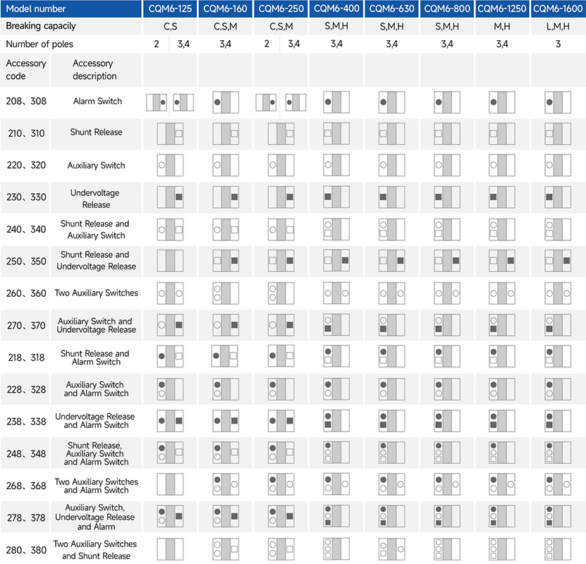
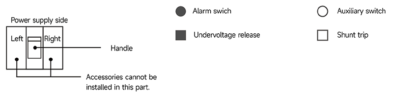
CHAC offers a right-side auxiliary switch, a left-side shunt release and a left-side undervoltage release.
For accessory codes 220, 320, 240, 340, 270 and 370, the auxiliary switch can provide two contact pairs. Specify this requirement when ordering.
For accessory codes 250 and 350, the shunt release and undervoltage release on frames 400 and above are available only for 3-pole circuit breakers.
Main Technical Parameters
| Số hiệu mô hình | CQM6-125 | CQM6-160 | |||||
|---|---|---|---|---|---|---|---|
| Rated current of frame level Inm(A) | 125 | 160 | |||||
| Số lượng cực | 2,3,4 | 3,4 | |||||
| Rated current In(A),at 40°C,50°C,55°C | 16,20,25,32,40,50,63,80,100,125 | 16,20,25,32,40,50,63,80,100,125,140,160 | |||||
| Rated operating voltage Ue(V),AC 50/60Hz | 400/415 | 400/415 | |||||
| Rated insulation voltage Ui (V) | 800 | 800 | |||||
| Rated impulse withstand voltage Uimp(KV) | 8 | 8 | |||||
| Breaking capacity designation | C | S | C | S | M | ||
| Short-circuit breaking capacity Icu/Ics(kA) | AC400/415V | 15/8 | 25/18 | 25/18 | 35/25 | 50/35 | |
| Selectivity category | A | A | A | A | A | ||
| Number of operating cycles(cycle) | ON | 6000 | 6000 | ||||
| OFF | 10000 | 10000 | |||||
| Trip mechanisms and protection types | Magnetic trip | Power distribution protection | ● | ● | ● | ● | ● |
| Motor protection | ● | ● | ● | ● | ● | ||
| Thermal-magnetic trip | Power distribution protection | ● | ● | ● | ● | ● | |
| Motor protection | ● | ● | ● | ● | ● | ||
| Phụ kiện | Các liên hệ phụ | ● | ● | ● | ● | ● | |
| Alarm contacts | ● | ● | ● | ● | ● | ||
| Shunt disconnect | ● | ● | ● | ● | ● | ||
| Undervoltage detent | ● | ● | ● | ● | ● | ||
| Manual operating mechanism | ● | ● | ● | ● | ● | ||
| Motorized operating mechanism | ● | ● | ● | ● | ● | ||
| Backplane wiring | ● | ● | ● | ● | ● | ||
| Inserted | ● | ● | ● | ● | ● | ||
| Coupling plate | ● | ● | ● | ● | ● | ||
| Partition between phases | ● | ● | ● | ● | ● | ||
| Derivative products | Dedicated for prepayment electric meters | ● | ● | ● | ● | ● | |
| Overload alarm without trip | – | – | ● | ● | ● | ||
| Overall dimensions (mm) (a–b–c–ca) | 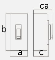 |
3 P | 75×130×68×91 | 90×155×70×95 | 90×155×85 ×109 | ||
| 4 P | 100×130×68×91 | 120×155×70×95 | 120×155×85 ×109 | ||||
Note: ● indicates an available optional accessory; – indicates that the accessory is not available.
Main Technical Parameters
| Số hiệu mô hình | CQM6-250 | CQM6-400 | CQM6-630 | ||||||||
|---|---|---|---|---|---|---|---|---|---|---|---|
| Rated current of frame level Inm(A) | 250 | 400 | 630 | ||||||||
| Số lượng cực | 2,3,4 | 3,4 | 3,4 | ||||||||
| Rated current In(A),at 40°C,50°C,55°C | 100,125,140,160,180,200,225,250 | 250,315,350,400 | 250,315,350,400,500,630 | ||||||||
| Rated operating voltage Ue(V),AC 50/60Hz | 400/415 | 400/415 | 400/415 | ||||||||
| Rated insulation voltage Ui (V) | 800 | 800 | 800 | ||||||||
| Rated impulse withstand voltage Uimp(KV) | 8 | 8 | 8 | ||||||||
| Breaking capacity designation | C | S | M | S | M | H | S | M | H | ||
| Short-circuit breaking capacity Icu/Ics(kA) | AC400/415V | 25/18 | 35/25 | 50/35 | 35/25 | 50/35 | 70/50 | 35/25 | 50/35 | 70/50 | |
| Selectivity category | A | A | A | A | A | A | A | A | A | ||
| Number of operating cycles (cycle) |
ON | 6000 | 3000 | 3000 | |||||||
| OFF | 10000 | 8000 | 8000 | ||||||||
| Trip mechanisms and protection types | Magnetic trip | Power distribution protection | ● | ● | ● | ● | ● | ● | ● | ● | ● |
| Motor protection | ● | ● | ● | ● | ● | ● | ● | ● | ● | ||
| Thermal-magnetic trip | Power distribution protection | ● | ● | ● | ● | ● | ● | ● | ● | ● | |
| Motor protection | ● | ● | ● | ● | ● | ● | ● | ● | ● | ||
| Phụ kiện | Các liên hệ phụ | ● | ● | ● | ● | ● | ● | ● | ● | ● | |
| Alarm contacts | ● | ● | ● | ● | ● | ● | ● | ● | ● | ||
| Shunt disconnect | ● | ● | ● | ● | ● | ● | ● | ● | ● | ||
| Undervoltage detent | ● | ● | ● | ● | ● | ● | ● | ● | ● | ||
| Manual operating mechanism | ● | ● | ● | ● | ● | ● | ● | ● | ● | ||
| Motorized operating mechanism | ● | ● | ● | ● | ● | ● | ● | ● | ● | ||
| Backplane wiring | ● | ● | ● | ● | ● | ● | ● | ● | ● | ||
| Inserted | ● | ● | ● | ● | ● | ● | ● | ● | ● | ||
| Coupling plate | ● | ● | ● | ● | ● | ● | ● | ● | ● | ||
| Partition between phases | ● | ● | ● | ● | ● | ● | ● | ● | ● | ||
| Derivative products | Dedicated for prepayment electric meters | ● | ● | ● | ● | ● | ● | ● | ● | ● | |
| Overload alarm without trip | ● | ● | ● | ● | ● | ● | ● | ● | ● | ||
| Overall dimensions (mm) (a-b-c-ca) | |
3 P | 105×165×70×95 | 105×165×93×118 | 140×257×107×156 | 140×257×107×156 | |||||
| 4 P | 140×165×70×95 | 140×165×93×118 | 185×257×107×156 | 185×257×107×156 | |||||||
Note: ● indicates an available optional accessory; – indicates that the accessory is not available.
Main Technical Parameters
| Số hiệu mô hình | CQM6-800 | CQM6-1250 | CQM6-1600 | |||||||
|---|---|---|---|---|---|---|---|---|---|---|
| Rated current of frame level Inm(A) | 800 | 1250 | 1600 | |||||||
| Số lượng cực | 3,4 | 3,4 | 3 | |||||||
| Rated current In(A),at 40°C,50°C,55°C | 500,630,700,800 | 800,1000,1250 | 800,1000,1250,1400,1500,1600 | |||||||
| Rated operating voltage Ue(V),AC 50/60Hz | 400/415 | 400/415 | 400/415V | 660/690V | ||||||
| Rated insulation voltage Ui (V) | 800 | 1000 | 1000 | |||||||
| Rated impulse withstand voltage Uimp(KV) | 8 | 12 | 12 | |||||||
| Breaking capacity designation | S | M | H | M | H | L | M | H | ||
| Short-circuit breaking capacity Icu/Ics(kA) | AC400/415V | 35/25 | 50/35 | 70/50 | 50/35 | 70/55 | 70/20 | 100/35 | 100/50 | |
| Selectivity category | A | A | A | A | A | A | A | A | ||
| Number of operating cycles (cycle) |
ON | 1000 | 1000 | 500 | ||||||
| OFF | 3000 | 3000 | 3000 | |||||||
| Trip mechanisms and protection types | Magnetic trip | Power distribution protection | ● | ● | ● | ● | ● | ● | ● | ● |
| Motor protection | ● | ● | ● | ● | ● | ● | ● | ● | ||
| Thermal-magnetic trip | Power distribution protection | ● | ● | ● | ● | ● | ● | ● | ● | |
| Motor protection | ● | ● | ● | ● | ● | ● | ● | ● | ||
| Phụ kiện | Các liên hệ phụ | ● | ● | ● | ● | ● | ● | ● | ● | |
| Alarm contacts | ● | ● | ● | ● | ● | ● | ● | ● | ||
| Shunt disconnect | ● | ● | ● | ● | ● | ● | ● | ● | ||
| Undervoltage detent | ● | ● | ● | ● | ● | ● | ● | ● | ||
| Manual operating mechanism | ● | ● | ● | ● | ● | ● | ● | ● | ||
| Motorized operating mechanism | ● | ● | ● | ● | ● | ● | ● | ● | ||
| Backplane wiring | ● | ● | ● | ● | ● | ● | ● | ● | ||
| Inserted | ● | ● | ● | ● | ● | ● | ● | ● | ||
| Coupling plate | ● | ● | ● | ● | ● | ● | ● | ● | ||
| Partition between phases | ● | ● | ● | ● | ● | ● | ● | ● | ||
| Derivative products | Dedicated for prepayment electric meters | ● | ● | ● | ● | ● | ● | ● | ● | |
| Overload alarm without trip | ● | ● | ● | ● | ● | ● | ● | ● | ||
| Overall dimensions (mm) (a–b–c–ca) | |
3 P | 210×275×113×162 | 210×275×113×162 | 210×268×161×240 | |||||
| 4 P | 280×275×113×162 | 280×275×113×162 | ||||||||
Note: ● indicates an available optional accessory; – indicates that the accessory is not available.
Đặc tính vận hành
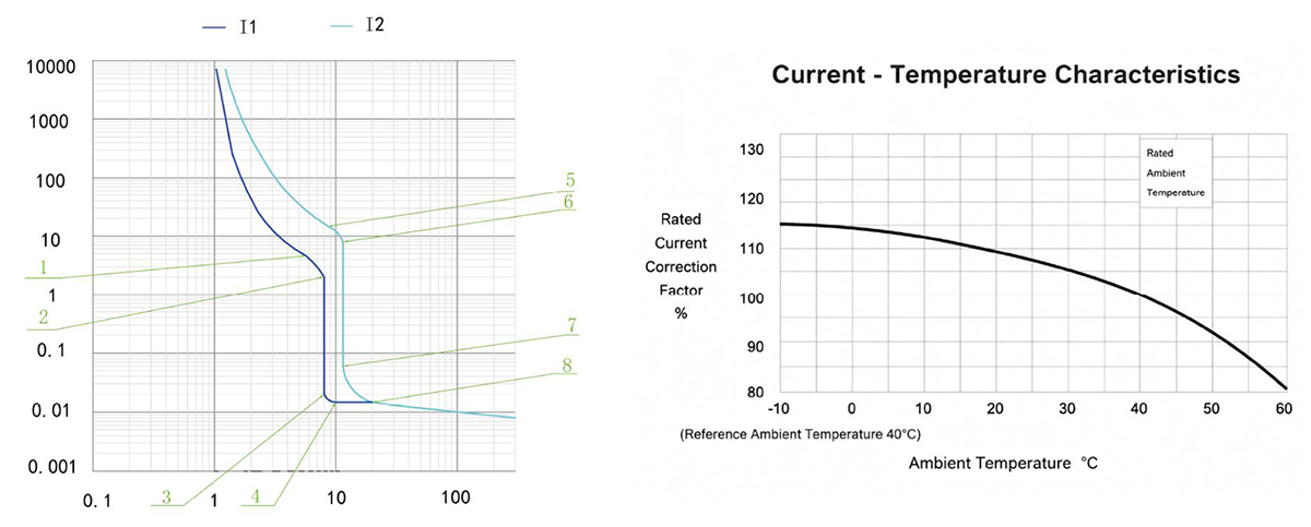
The following table gives the inverse-time operating characteristics for distribution protection with all poles energised at an ambient temperature of +40°C, without humidity compensation.
| Test current designation | Setting current multiple | Conventional time | Initial state |
|---|---|---|---|
| In≤63 63<In | |||
| Conventional non-tripping current | 1.05 | ≥1h ≥2h | Cool state |
| Conventional tripping current | 1.30 | <1h <2h | Hot state |
The following table gives the inverse-time operating characteristics for motor protection with all poles energised at an ambient temperature of +40°C, without humidity compensation.
| Test current designation | Setting current multiple | Conventional time | Initial state |
|---|---|---|---|
| In≤800 | |||
| Conventional non-tripping current | 1.0 | ≥2h | Cool state |
| Conventional tripping current | 1.2 | <2h | Hot state |
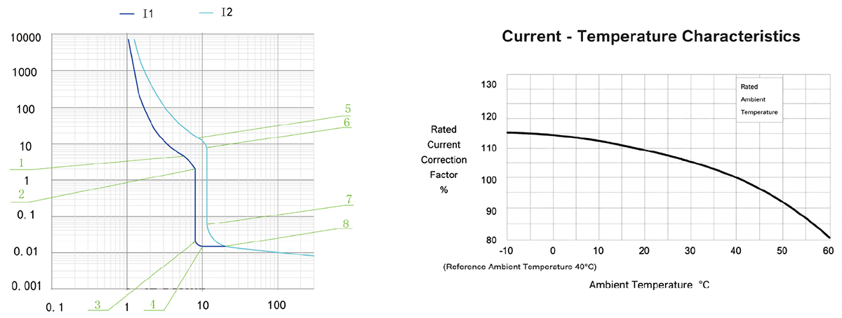
The operating-characteristics reference gives an instantaneous trip current setting of 10In for distribution protection. Confirm the applicable trip-unit setting for the ordered configuration.
The operating-characteristics reference gives an instantaneous trip current setting of 12In for motor protection.
The stated accuracy of the instantaneous trip current setting is 20% of the setting value.
CQM6-125 Operating Characteristic Curve
CQM6-160 Operating Characteristic Curve
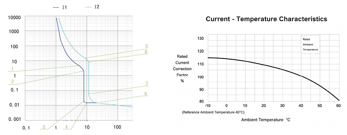
CQM6-250 Operating Characteristic Curve
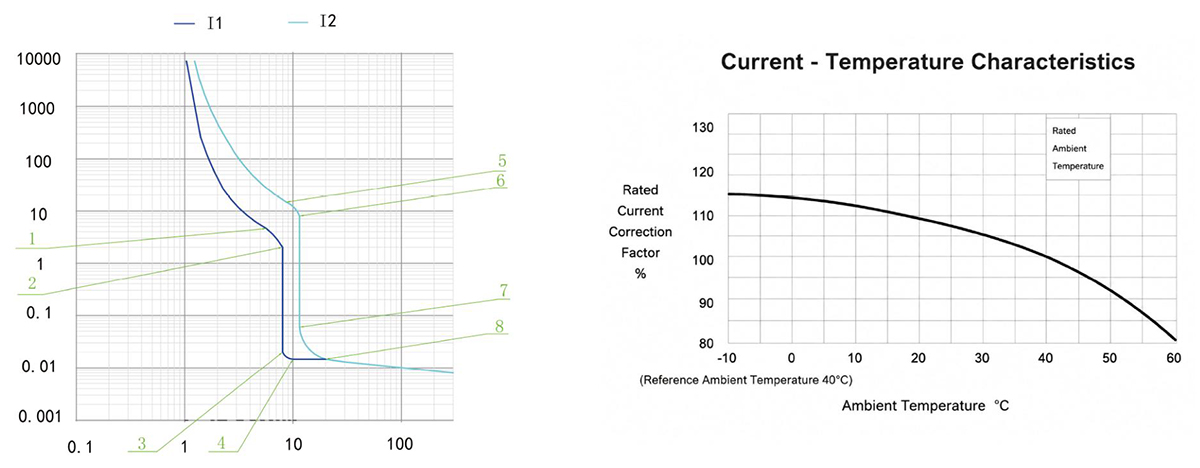
CQM6-400 / 630 Operating Characteristic Curve
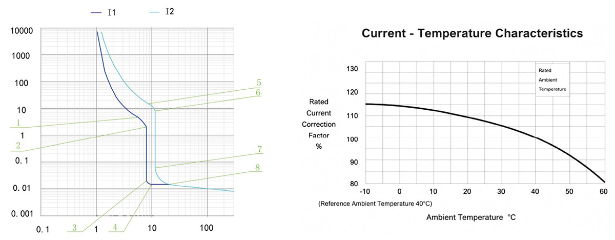
CQM6-800 Operating Characteristic Curve
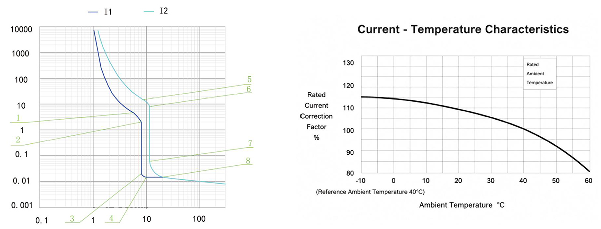
CQM6-1250 Operating Characteristic Curve
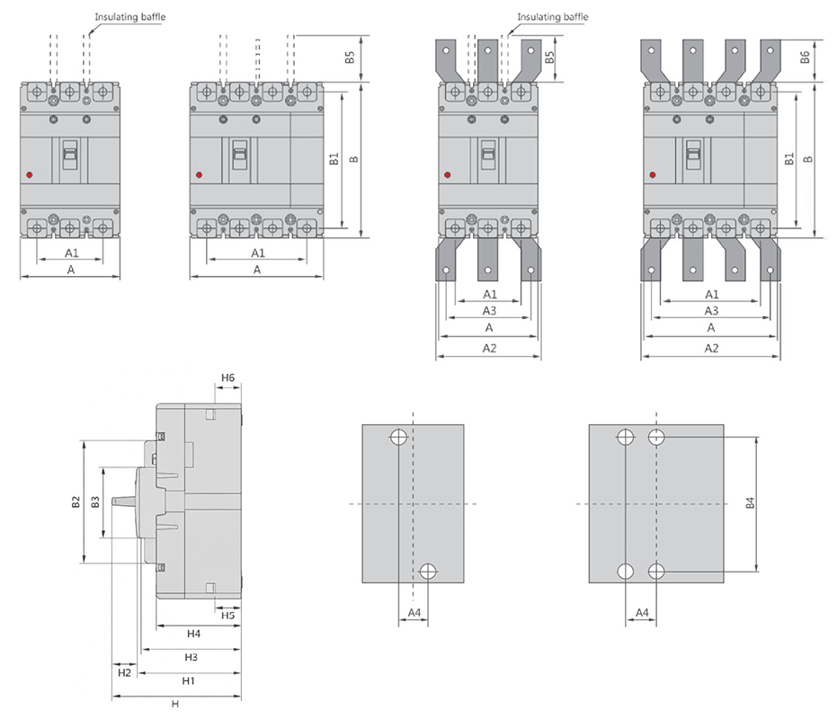
CQM6-125~1250 Outline and Installation Dimensions(mm)
CQM6-1600 Outline and Installation Dimensions(mm)
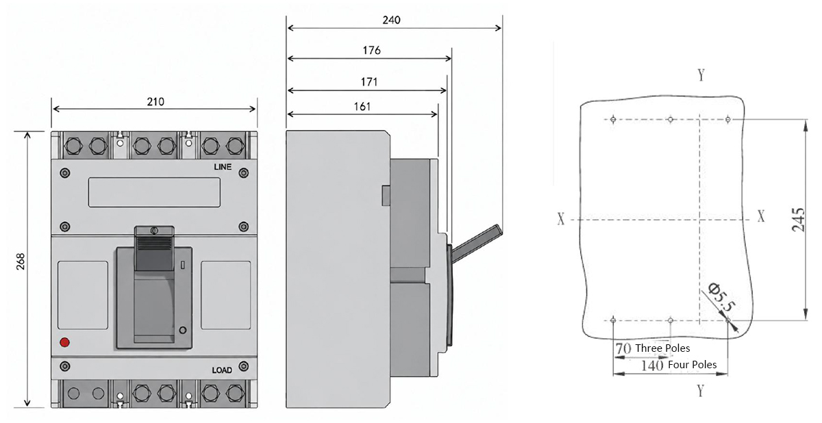
| Molded case circuit breaker | Overall dimension | Installation dimensions | Boit | |||||||||||||||||||||
|---|---|---|---|---|---|---|---|---|---|---|---|---|---|---|---|---|---|---|---|---|---|---|---|---|
| A | A1 | A2 | A3 | B | B1 | B2 | B3 | B5 | B6 | H | H1 | H2 | H3 | H4 | H5 | H6 | A4 | B4 | ||||||
| 3P | 4P | 3P | 4P | 3P | 4P | 3P | 4P | |||||||||||||||||
| CQM6-125CSM | 75 | 100 | 50 | 75 | – | – | – | – | 130 | 114 | 85 | 50 | 48 | – | 91 | 73.4 | 2.4 | 68 | 61 | 23.9 | 24 | 25 | 111 | M6 |
| CQM6-160CS | 90 | 120 | 60 | 90 | – | – | – | – | 155 | 134 | 103 | 50 | 48 | – | 95 | 75.5 | 2.1 | 70 | 62 | 24 | 24.8 | 30 | 132 | M8 |
| CQM6-160M | 90 | 120 | 60 | 90 | – | – | – | – | 155 | 134 | 103 | 50 | 48 | – | 109.5 | 90 | 2.1 | 85 | 76.5 | 23.6 | 25 | 30 | 132 | M8 |
| CQM6-250CS | 105 | 140 | 70 | 105 | – | – | – | – | 165 | 144 | 102 | 50 | 97 | – | 95 | 74.2 | 2.7 | 70 | 61.4 | 22.3 | 23.1 | 35 | 126 | M8 |
| CQM6-250M | 105 | 140 | 70 | 105 | – | – | – | – | 165 | 144 | 102 | 50 | 95 | – | 118.5 | 97.7 | 2.7 | 93.4 | 84.8 | 22.9 | 23.3 | 35 | 126 | M8 |
| CQM6-400SMH | 140 | 185 | 70 | 132 | 140 | 196 | 112 | 168 | 257 | 230 | 179 | 90 | 103 | 42 | 156 | 111.7 | 3.5 | 107.5 | 99.5 | 30.9 | 32.4 | 44 | 194 | M10 |
| CQM6-630SMH 400A | 140 | 185 | 88 | 132 | 140 | 196 | 112 | 168 | 257 | 230 | 179 | 90 | 103 | 42 | 156 | 111.7 | 3.5 | 107.5 | 99.5 | 30.9 | 32.4 | 44 | 194 | M10 |
| CQM6-630SMH 630A | 140 | 185 | 88 | 132 | 140 | 196 | 112 | 168 | 257 | 230 | 179 | 90 | 103 | 42 | 156 | 111.7 | 3.5 | 107.5 | 99.5 | 33.2 | 34 | 44 | 194 | M10 |
| CQM6-800SMH 630A | 210 | 280 | 140 | 210 | 180 | 250 | 140 | 210 | 275 | 243 | 192 | 90 | 103 | 87 | 162.5 | 118 | 2.7 | 113.4 | 105.5 | 28.3 | 30.4 | 70 | 242.5 | M12 |
| CQM6-800SMH 800A | 210 | 280 | 140 | 210 | 180 | 250 | 140 | 210 | 275 | 243 | 192 | 90 | 103 | 87 | 162.5 | 118 | 2.7 | 113.4 | 105.5 | 29 | 32.6 | 70 | 242.5 | M12 |
| CQM6-1250SMH | 210 | 280 | 140 | 210 | 180 | 250 | 140 | 210 | 275 | 243 | 192 | 90 | 103 | 87 | 162.5 | 118 | 2.7 | 113.4 | 105.5 | 31.3 | 34.4 | 70 | 242.5 | M10 |
| CQM6-1600LMH | 210 | – | 140 | – | – | – | – | – | 268 | 240 | 118 | 97 | 110 | – | 240 | 171 | 5 | 161 | 150 | 33 | 34 | 70 | 245.0 | M10 |
Tại sao nên chọn CHAC
Với hơn 30 năm kinh nghiệm sản xuất, hơn 1100 nhân viên, hơn 100M cột
công suất hàng năm và 90% sản xuất tự động, CHAC cung cấp công suất sản xuất ổn định và nghiêm ngặt
kiểm soát chất lượng cho các khách hàng OEM/ODM trên toàn cầu. Hệ thống sản xuất nội bộ của chúng tôi hỗ trợ dài hạn
hợp tác cho các thương hiệu điện, nhà nhập khẩu và nhà phân phối.

30+
NĂM KINH NGHIỆM
Chuyên sản xuất thiết bị điện hạ thế

1100+
CÔNG NHÂN
Đội ngũ chuyên nghiệp đảm bảo chất lượng và giao hàng ổn định

100 triệu người
Sức chứa hàng năm của các cột
Năng lực sản xuất quy mô lớn để đáp ứng nhu cầu toàn cầu

90%
SẢN XUẤT TỰ ĐỘNG
Tự động hóa nâng cao cho hiệu quả cao và tính nhất quán
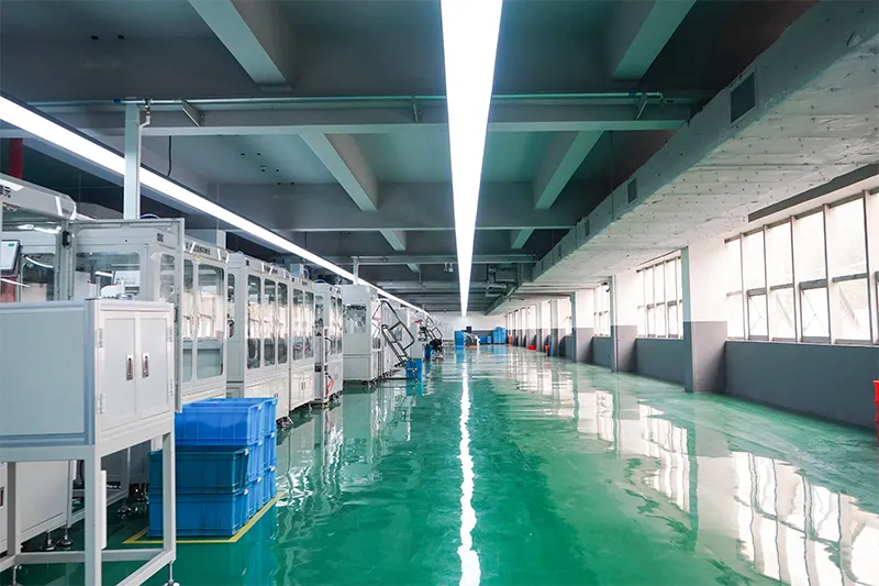
Dây chuyền lắp ráp tự động

Phòng thí nghiệm kiểm nghiệm
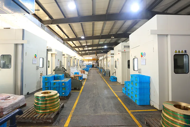
Xay và dập
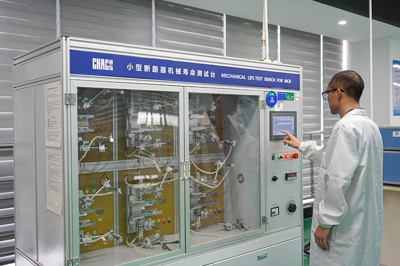
Kiểm tra chất lượng



Hệ thống kiểm soát chất lượng nghiêm ngặt đảm bảo mọi sản phẩm đều đáp ứng các tiêu chuẩn toàn cầu.
Chúng tôi có thể tùy chỉnh những gì?
For CQM6 projects, CHAC can review private-label marking, packaging, approved appearance options, published 16–1600A electrical configurations and technical-document requirements. Requests outside the published range are subject to engineering evaluation, testing, minimum order quantity and project feasibility.

Phần đính kèm
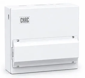
Thiết kế
Kích thước, cấu trúc và chi tiết lắp đặt của thiết bị được tùy chỉnh.

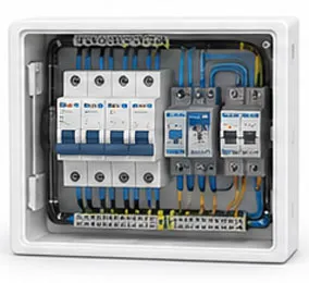
Về nội bộ
Cấu hình
Tùy chọn bố trí nội bộ và sắp xếp các thành phần linh hoạt.

Xây dựng thương hiệu &
Logo
Logo nhãn hiệu riêng, bảng tên và nhận diện thương hiệu.
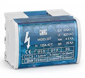

Gói bao bì
Thiết kế
Dịch vụ sản xuất thùng carton, nhãn mác, hướng dẫn sử dụng và các giải pháp đóng gói tùy chỉnh.

Điện
Cấu hình
Thiết lập điện được điều chỉnh theo yêu cầu ứng dụng.
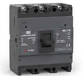

Chứng nhận
Hỗ trợ
Hỗ trợ các tiêu chuẩn và yêu cầu tuân thủ của thị trường mục tiêu.
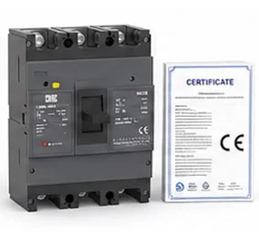
Tải xuống
Bộ ngắt mạch dạng hộp CQM6
Tổng quan đầy đủ về các linh kiện điện hạ thế và tài liệu tham khảo để lựa chọn sản phẩm.
Cần tài liệu kỹ thuật?
Hãy liên hệ với chúng tôi để nhận bảng thông số kỹ thuật, chứng chỉ, bản vẽ, hướng dẫn lựa chọn hoặc hỗ trợ các dự án OEM/ODM.
CQM6 Product FAQ
What is the CQM6 MCCB used for?
The CQM6 is specified for overload and short-circuit protection in AC systems at the voltage listed for the ordered frame within the published 16–1600A range. Suitability depends on the fault study, conductor coordination, enclosure and local rules.
How does the CQM6 molded case circuit breaker work?
The protection mechanism responds to the fault conditions stated for this model: overload and short-circuit protection. Trip behaviour, settings and interruption duty must be checked against the ordered frame and product instructions.
How do I choose the CQM6 rated current and poles?
Start with the design current and conductor calculation, then choose a published current within 16–1600A and poles from 2P / 3P / 4P, depending on frame; CQM6-1600: 3P. Neutral treatment, fault level, ambient conditions and coordination also need review.
What breaking capacity should I check on the CQM6?
Use the declared C/S/M/H/L classes, with Icu up to 100kA for the listed CQM6-1600 660/690V configurations; verify the exact frame and voltage for the exact frame, voltage and configuration. The prospective short-circuit current at the installation point must be within the applicable duty; a larger ampere value alone is not a selection rule.
Can the CQM6 replace an MCB or an earth-leakage device?
An MCCB is not automatically a like-for-like replacement. The CQM6 provides overload and short-circuit protection; residual-current protection, DC interruption, adjustable settings and other functions must be confirmed separately from the project requirement.
How should the CQM6 be installed and tested?
Use only the exact model drawing, terminal identification and accessory instructions. A qualified person should verify isolation, conductor size, torque, clearances, settings, fault duty and functional tests before energising the circuit.
Confirm the Right CQM6 Configuration
Send the frame, rated current, poles, protection function, system voltage, expected fault level, destination market and quantity. CHAC will review the request against the published model range.