A solar breaker can fit the DIN rail and carry the expected current while still being unsuitable for the circuit. The overlooked constraint may be the string’s cold open-circuit voltage, a required pole connection or another source feeding a fault. Array power alone will not reveal those limits. The selection also changes with location: a PV string, combiner output, battery branch and inverter AC output do not share the same assumptions. This guide separates those boundaries and shows what to collect before choosing a device, including an illustrative voltage calculation and the checks that should be repeated when a system is expanded.
The short answer is: a solar circuit breaker must match the circuit’s maximum voltage, design current, prospective fault current, polarity, permitted pole connection and isolation plan. Array wattage or an AC current label cannot establish compatibility. Record the system diagram and exact product instructions, then have the responsible designer verify the circuit under the applicable installation rules. The device’s location matters: PV strings, storage circuits and inverter AC outputs require separate checks.
PV protection is a system decision. A string, combiner, inverter DC input, battery branch and AC output can have different sources, fault paths and switching duties. A product that is appropriate at one boundary is not automatically appropriate at the next, even when the front label appears similar.
What does a solar breaker protect?
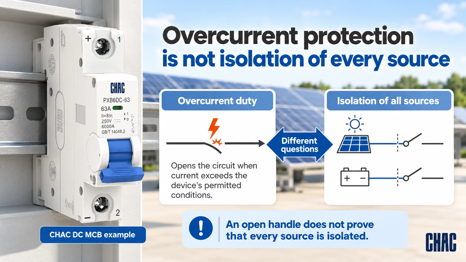
A solar breaker is an overcurrent device intended for a defined DC or AC circuit. On the PV side, it may open a string or feeder when the documented current exceeds the device’s permitted conditions; it may also provide switching or isolation only when the exact product is designed and marked for that function. It does not automatically provide surge protection, residual-current protection, arc-fault detection or safe isolation of every source.
PV modules can remain energised in daylight, and a battery or inverter can feed a different part of the same installation. The open handle of one device therefore does not prove that all terminals are dead. Show each source and isolation point on the project one-line, and use the local safe-isolation procedure.
How do you check PV and DC breaker compatibility?
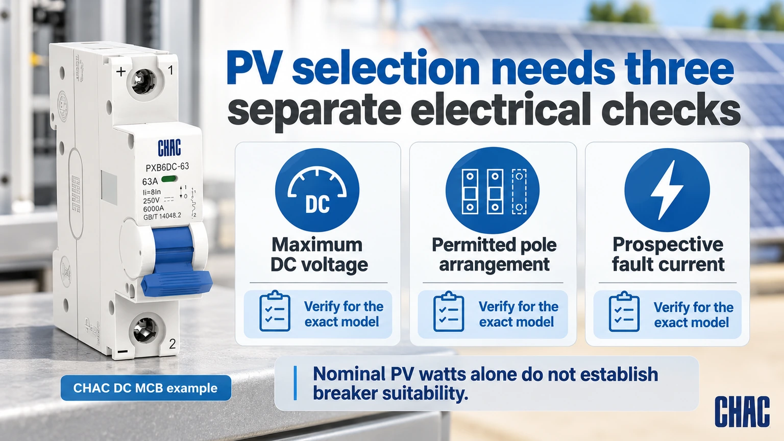
Start with the highest voltage that can appear across the device, not the module’s nominal operating voltage. For a series string, collect the module open-circuit voltage, temperature coefficient, series count and lowest design temperature specified by the project method. Then compare that result with the exact breaker’s published DC voltage for the permitted pole and terminal arrangement. If any input is missing, the defensible status is “selection pending,” not a guessed rating.
Current is a separate check. Record the source short-circuit or design current, parallel strings, conductor allowable current, ambient and installation conditions, and any battery or converter contribution. A solar panel breaker selected from watts divided by nominal voltage may be useful as an early estimate, but it does not establish interrupting duty, reverse-current exposure or conductor protection.
| Check | Evidence to collect | Boundary it supports |
|---|---|---|
| Maximum DC voltage | String layout, module open-circuit voltage, temperature data and design temperature | Device voltage rating and permitted pole connection |
| Continuous design current | Module or source data, parallel paths and applicable design method | Breaker rating or setting and conductor coordination |
| Prospective fault current | Fault study showing PV, battery, converter and backfeed contributions | Required interrupting capability and coordination |
| Polarity and poles | Grounding arrangement, conductors to open and exact manufacturer diagram | Terminal orientation and series-pole use, if permitted |
| Installation conditions | Enclosure, ambient, altitude, conductor limits, torque and access | Derating, fit, serviceability and inspection |
AC and DC interruption are not interchangeable assumptions. An AC nameplate is not a published DC rating, and a statement that a breaker is non-polarised does not prove that every fault direction is covered. For product screening, the MCB product category is only a starting point; request the exact model data sheet, wiring diagram and installation instructions.
How can cold weather change the string voltage calculation?
The following example illustrates the arithmetic only. Assume 12 identical modules, each with a 45 V open-circuit voltage at 25°C, a voltage temperature coefficient of −0.30%/°C and a project design minimum temperature of −10°C. These are assumed inputs, not CHAC product specifications or measured project data.
The reference string voltage is 12 × 45 = 540 V. The temperature change is −35°C, so the simplified linear correction is (−0.003) × (−35) = +0.105, or a 10.5% increase. The resulting illustrative cold open-circuit voltage is 540 × 1.105 = 596.7 V. This shows why a nominal operating voltage can be a poor basis for screening a breaker.
The result does not approve a 600 V device. The actual module manufacturer’s method, tolerances, adopted installation rules and design temperature still control, along with the breaker’s exact DC pole connection and rating. Check whether the coefficient is stated in percent per degree or volts per degree; using one as the other gives the wrong result. Keep the source datasheet and calculation with the string schedule so a module substitution can be reviewed.
Where are the wiring boundaries in a PV system?
Draw the protection boundary before choosing the device. The PV array and combiner may be exposed to string backfeed; the inverter DC terminals have their own switching and connection requirements; a battery branch can deliver fault current in a different direction; and the AC output follows another code and equipment scope. Do not merge those assumptions into one generic “solar breaker” specification.
| Boundary | Question for the designer | Typical procurement evidence |
|---|---|---|
| PV string or sub-array | What is the cold maximum voltage, source current and possible reverse current from parallel strings? | Array one-line, module data, string count and DC connection diagram |
| Combiner or DC feeder | Which strings and conductors contribute to a fault at this point? | Fault-current calculation, conductor schedule and coordination review |
| Inverter DC input | What switching, polarity and terminal conditions does the inverter manufacturer require? | Inverter manual, breaker instructions and isolation sequence |
| Battery or storage branch | Can the battery or converter feed the fault, and is the device approved for that duty? | Storage design, fault contribution and exact DC interrupting evidence |
| AC output and distribution | Which AC protective functions and local rules apply after conversion? | AC one-line, adopted code requirements and equipment ratings |
Keep DC conductors short, supported and separated as required by the installation design; observe the manufacturer’s terminal, torque, bending and enclosure limits. A wiring diagram from a similar model is not evidence for a substitute. If a device is polarity-sensitive, mark the required direction at the panel and verify it during commissioning.
Which protection option fits a new installation?
The honest answer depends on the circuit role. A string breaker, DC isolator, fuse, surge protective device and AC feeder breaker solve different problems. A new installation should map those functions separately, then select products that are documented for the same voltage, current, fault and connection conditions.
| Option | Use it to answer | Do not infer |
|---|---|---|
| DC circuit breaker | Can the device interrupt the specified overload or fault within its declared DC conditions? | That it provides surge, earth-fault or arc-fault protection |
| DC isolator/disconnector | Can qualified personnel isolate the defined circuit for service? | That it provides overcurrent interruption |
| PV fuse or string protection | Does the source and array design require a current-limiting protective element? | That a fuse can replace every required switching function |
| SPD or other supplementary protection | Is transient or fault protection required by the design and adopted rules? | That a breaker limits transient voltage |
For a model-family review, CHAC’s PXB6DC-63 DC miniature circuit breaker và PXB6HDC-63 DC miniature circuit breaker pages can be included in a document request. Final suitability still depends on the exact variant, project data and destination-market requirements; this article does not assign a rating or certify an installation.
What does the 33% rule mean, and which code applies?
“The 33% rule” is not a universal solar-breaker sizing rule. The phrase is used informally in some design discussions for a calculation or code allowance, but its meaning depends on the adopted NEC edition, the exact section, the equipment arrangement and the authority having jurisdiction. Confirm the cited section and arithmetic with the responsible designer; never use the phrase to bypass a voltage, conductor or interrupting-duty check.
For US projects, NFPA’s NEC resource identifies the installation-code framework; the locally adopted edition and amendments govern. IEC 60947-2:2024 is a low-voltage circuit-breaker product standard with a defined public scope. Its catalogue record is not evidence that a particular breaker is certified, that its pole connection suits this PV circuit or that an installed system complies.
Unsupported compliance claims can produce rejected submittals, inspection delays, substitutions, returns and field rework. Keep the adopted code reference, one-line diagram, data sheets, installation instructions, declarations or listings, and commissioning record together for the exact catalog number.
Which system changes require the PV protection review to be repeated?
Adding another parallel string changes more than the energy estimate. It can change combined current and reverse-current exposure at a faulted string. Adding storage introduces another possible source of fault current; changing an inverter can alter connection, isolation or converter-related requirements. Review those boundaries before keeping the previous breaker specification.
Maintain a short change record: what changed, which circuit boundaries are affected, which calculation or instruction must be checked and who approved the revision. Update the one-line diagram and string schedule together. A replacement described as “the same watts” may have a different open-circuit voltage or short-circuit current, so total array power is not a substitute for comparing module data.
If the inverter reports a DC fault while the breaker remains closed, first identify what the inverter’s fault code actually means. If the breaker has operated, preserve its indication and the operating conditions. Neither observation alone justifies a higher breaker rating. Qualified personnel should investigate using the exact device instructions and system diagram, including every source that may remain energized.
What mistakes should buyers avoid?
- Choosing by panel watts or an AC ampere label without checking maximum DC voltage and fault current.
- Copying a series-pole or polarity arrangement from another model’s diagram.
- Treating normal bidirectional current as proof of bidirectional fault interruption.
- Assuming a breaker also supplies isolation, surge, earth-fault or arc-fault functions.
- Accepting a substitute without repeating the same one-line, conductor, enclosure and code review.
Compare suppliers by documentation control as well as unit cost: exact part-number traceability, revision control, connection diagrams, terminal limits, environmental data and replacement support reduce total project risk. Ask the supplier to identify what is verified and what remains the installer’s responsibility.
Các câu hỏi thường gặp
Which breaker is best for solar?
The best breaker is the one whose published DC voltage, current, interrupting capability, polarity, pole arrangement and installation instructions match the documented circuit. There is no universal best model; PV string, inverter, battery and AC boundaries may require different products.
What is the 33% rule in solar panels?
It is an informal phrase, not a universal rating rule. Confirm the exact NEC section, edition, bus or conductor arrangement and local authority interpretation before applying any calculation; it does not replace PV voltage, current and fault checks.
Why is plug-in solar illegal?
Plug-in generation may be prohibited or restricted in a jurisdiction because backfeed, branch-circuit loading, disconnecting, grounding, labeling or rapid-shutdown requirements have not been demonstrated. Legality varies by market and installation, so obtain approval under the adopted code rather than relying on a generic kit claim.
Is there a breaker specifically for solar panels?
Yes, DC-rated breakers and other protective devices are used in PV systems, but the correct choice depends on the string or feeder voltage, design current, fault contribution, polarity and wiring arrangement. A product described as “for solar” is not enough evidence without its exact instructions.
What is a PV breaker for solar?
A PV breaker is an overcurrent protective device selected for a defined photovoltaic circuit. Its manufacturer must declare the relevant DC ratings and connection conditions. Match those instructions to the actual string or feeder, including maximum voltage, design current, fault contribution and any permitted isolation function.
What is solar breaker used for?
It is used to interrupt or isolate a documented PV-related circuit when the device is designed and marked for that function. It does not automatically protect the inverter, battery, AC system, surge environment or every conductor in the installation.
Tham khảo
- NFPA 70 (NEC) — official installation-code resource; adopted edition and local rules control
- IEC 60947-2:2024 — official low-voltage circuit-breaker publication and scope
- US Department of Energy: Solar Photovoltaic Technology Basics — system context
Conclusion
The dependable rule is simple: define the PV boundary, calculate from the real source data, and approve the exact wiring and device evidence together. If a rating, pole connection or fault direction is not documented, it is not yet a safe assumption. For model matching, wiring documentation or project-specific solar protection guidance, contact Điện CHAC with the one-line diagram, system data and destination market.