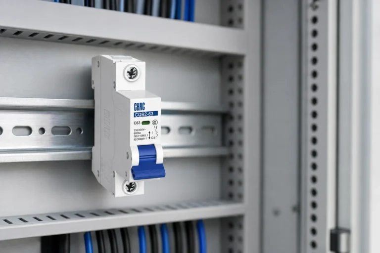
Consider a typical commissioning scenario: when facilities engineer Maya in Dallas replaced a tripping device with a visually similar 50 A unit, she closed the panel and the equipment shut down again within seconds. The replacement was not faulty. She had matched the handle rating but missed the circuit voltage, required pole count, and common-trip function. The correct decision began with the wiring diagram and the complete ratings of the 50 amp breaker, not with “50 A” alone.
ملخص: In a typical US 120/240 V split-phase system, a single-pole 50 A breaker usually serves a 120 V line-to-neutral circuit, while a double-pole 50 A breaker usually serves a 240 V line-to-line circuit and disconnects both ungrounded conductors together. That means roughly 6,000 VA versus 12,000 VA at the same current before continuous-load and equipment-specific limits are applied. Do not add two 50 A poles and call the breaker 100 A. Confirm the supply, load diagram, neutral requirement, trip mechanism, conductor and terminal ratings, panel compatibility, and available fault current before selecting a device.
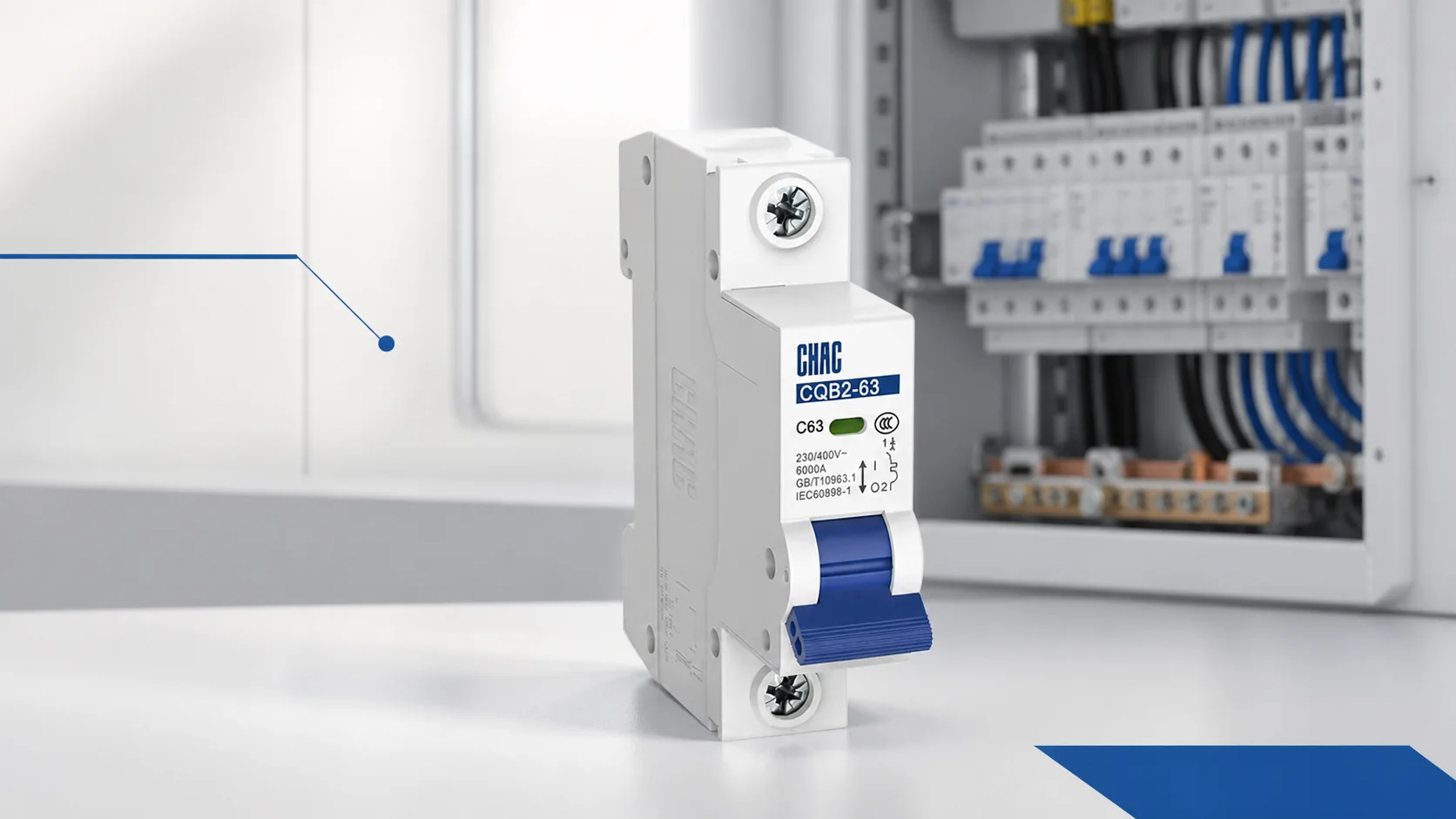
A single-pole breaker monitors and opens one protected pole. On a common North American split-phase service, it normally connects one ungrounded conductor to a line-to-neutral load. A double-pole breaker monitors two poles and operates them as one device; it is the usual arrangement for a line-to-line load connected across both legs. These descriptions concern protection and disconnection. They are not universal voltage labels, because other countries and distribution systems use different conductor-to-earth and conductor-to-conductor voltages.
How pole count changes voltage and available circuit power
The first design question is not “Which breaker looks right?” but “Which current-carrying conductors must be protected and opened together?” In a nominal 120/240 V split-phase system, a 50 A single-pole circuit at 120 V has a theoretical apparent-power ceiling of 6,000 VA. A 50 A double-pole circuit at 240 V has a theoretical ceiling of 12,000 VA because the same 50 A flows through both ungrounded conductors at twice the voltage. The double-pole device does not provide 100 A; pole ratings are not added.
Those figures describe voltage multiplied by current, not permission to load the circuit continuously to the handle rating. Actual usable power depends on the load, power factor, efficiency, duty cycle, equipment instructions, and the governing installation rules. The same distinction matters in smaller branch circuits, as this explanation of watts available on a 15 amp circuit shows.
| نقطة قرار | Single-pole 50 A breaker | Double-pole 50 A breaker |
|---|---|---|
| Conductors protected | One ungrounded conductor | Two ungrounded conductors operated together |
| Typical US split-phase voltage | 120 V line to neutral | 240 V line to line |
| Theoretical apparent power | 6,000 VA at 120 V and 50 A | 12,000 VA at 240 V and 50 A |
| Current interpretation | 50 A through the protected pole | 50 A through each pole rather than 100 A to the load |
| Usual panel space | One compatible position | Two adjacent compatible positions on opposite legs |
| Primary selection risk | Assuming every 50 A load is 120 V | Ignoring common trip or the actual neutral requirement |
This is why a single pole breaker vs double pole breaker comparison must remain tied to a particular supply. A line-to-line single-phase load in a three-phase installation may also use two poles, while a three-phase load normally needs protection and disconnection for all phase conductors. Informal labels such as 220 V or 230 V are not enough. Use the one-line diagram, nominal system voltage, frequency, earthing arrangement, and equipment connection drawing.
Why common trip and neutral requirements are separate decisions
A two-pole breaker with an internal common-trip mechanism automatically opens both poles when either pole trips. NEC 240.15(B) generally requires a circuit breaker to open all ungrounded conductors of the circuit both manually and automatically, subject to the section’s specific permissions. This prevents one side of a 240 V circuit from remaining energized after the other side experiences a fault.
A listed handle tie provides simultaneous manual operation in applications where the code and equipment instructions permit it. It does not automatically turn two independent trip mechanisms into a common-trip device. Designers should establish whether the circuit needs simultaneous manual disconnection, automatic common trip, or both. A tandem breaker is also a different concept: it places two independent poles in a compact panel format and does not substitute for a two-pole breaker spanning the required bus positions. This distinction should be documented whenever an electrical panel upgrade changes circuit count or available spaces.
The neutral question comes from the load diagram rather than the breaker’s ampere rating. A pure 240 V load connected line to line normally does not need a neutral. Equipment that combines 240 V heating or motor loads with 120 V controls, lighting, or receptacles may need two ungrounded conductors plus a neutral. The neutral carries the imbalance between line-to-neutral loads; it does not pass through an ordinary two-pole overcurrent mechanism. Manufacturer instructions and local rules determine its size, termination, and whether a disconnect must switch it in a special application.
How load type affects continuous current and conductor sizing
Start with the equipment nameplate and installation instructions. Record the rated input current, supply voltage, duty classification, phase, frequency, and any marked maximum overcurrent protection. Under the NEC method used for many branch circuits, conductors and overcurrent protection for a continuous load are sized at not less than 125 percent of that load, subject to the applicable article, assembly ratings, and exceptions. A 40 A continuous load can therefore lead to a 50 A circuit. It does not follow that every appliance on a 50 A breaker may draw 50 A for three hours or more.
There is no universal conductor size for every 50 A installation. No. 6 AWG copper is common in some US applications, but conductor material, insulation rating, ambient temperature, bundling, installation method, and load calculation all matter. NEC 110.14(C) also limits ampacity according to equipment termination temperature provisions. A conductor that appears adequate in an ampacity table can still be unsuitable when the connected terminal is rated for a lower temperature. Voltage drop may call for a larger conductor on a long run even when minimum ampacity is satisfied.
EV charging, welding, and RV service show why amperage alone cannot select the circuit:
| تطبيق | What changes the decision | What to verify before choosing |
|---|---|---|
| EV supply equipment | Charging is treated as a continuous load under NEC Article 625 | Maximum continuous setting, hardwired or receptacle connection, equipment instructions, and required protection |
| Welder | Duty cycle and input-current characteristics may invoke category-specific sizing provisions | Nameplate data, permitted overcurrent protection, conductor calculation, and expected operating cycle |
| RV supply | A 50 A receptacle commonly provides 120/240 V with a neutral rather than a generic 240 V-only outlet | Receptacle configuration, feeder conductors, neutral and grounding arrangement, and applicable RV rules |
| Range or cooking equipment | Demand calculations and mixed 120/240 V internal loads may apply | Manufacturer circuit rating, neutral requirement, branch-circuit rules, and local amendments |
| Motor or transformer-related load | Starting current can be much higher than steady operating current | Inrush profile, trip curve, conductor protection, coordination, and equipment-specific code article |
Increasing the breaker rating to stop a nuisance trip is not a sound diagnostic method. Measure operating current, review startup behavior, inspect terminations, and compare the observed event with the time-current curve. Any change must remain within the conductor ampacity and the equipment’s permitted protective-device range.
Which ratings prove the breaker is suitable for the installation?
After voltage, poles, and load have been resolved, check the breaker’s voltage rating and interrupting rating. The interrupting rating must be at least the available fault current at the installation point under the applicable system conditions. A 50 A handle rating describes normal overcurrent protection; it says nothing about whether the device can safely interrupt a 5 kA, 10 kA, or higher prospective short circuit. A transformer or service upgrade can increase available fault current even when the connected load has not changed.
In North America, UL 489 covers molded-case circuit breakers, molded-case switches, and circuit-breaker enclosures within its scope. The exact catalog number must also be listed or classified for the panel where required. A breaker that clips onto the bus is not necessarily compatible: contact geometry, rejection features, heat-rise performance, enclosure evaluation, and manufacturer instructions all form part of the evidence.
For IEC markets, IEC 60898-1 addresses circuit breakers for household and similar installations within its defined limits, while IEC 60947-2 addresses circuit breakers used within low-voltage switchgear and controlgear. These are product-standard scopes and test frameworks; merely printing a standard number is not proof of conformity. Procurement teams should obtain documentation for the exact model and confirm that it applies to the destination market, installation category, utilization, and declared ratings.
When comparing a double pole 50 amp breaker, verify the complete product record: rated operational voltage, frequency, pole arrangement, trip curve or trip unit, breaking capacity, terminal conductor range, terminal temperature information, mounting system, panel or enclosure compatibility, ambient derating, and required approvals. This evidence prevents a visually plausible replacement from becoming a compliance or downtime problem.
A practical selection process reduces lifecycle risk
A low purchase price can disappear after engineering rework, rejected inspection, overheated connections, nuisance trips, production downtime, or an emergency replacement. A useful lifecycle comparison includes the breaker, any panel or enclosure changes, conductor work, labor, testing, documentation, spares, and the operational cost of an interruption. The correct pole configuration often costs less over the life of the installation because it avoids redesign and uncertain field substitutions.
Use a short evidence chain for each selection:
- Trace every ungrounded conductor and any neutral on the supply and equipment diagrams.
- Calculate the load under the article or regulation that applies to that equipment category.
- Confirm conductor ampacity using the material, insulation, ambient conditions, bundling, and terminal temperature limits.
- Compare available fault current with the documented interrupting rating.
- Verify the exact part number against the panel label, manufacturer instructions, mounting arrangement, and destination-market documentation.
CHAC Electric can support this review with low-voltage distribution product information and model-specific documentation. Treat a product-family page as a starting point; the final choice still has to match the project diagram, load data, installation code, and approval requirements.
أسئلة متكررة
Is a 50 amp breaker always double pole?
No. Single-pole and double-pole 50 A devices both exist. In a typical US split-phase panel, a 120 V line-to-neutral circuit may use one pole and a 240 V line-to-line circuit normally uses a two-pole common-trip breaker, but the actual supply and equipment diagram control the choice.
How many watts can a 50 amp single-pole breaker supply?
At 120 V, 50 A corresponds to 6,000 VA before continuous-load limits and load characteristics are considered. Real usable power can be lower because the design must account for duty, power factor, efficiency, equipment instructions, and applicable code requirements.
Does a double-pole 50 amp breaker provide 100 amps?
No. It carries up to its rated current through each pole as part of one circuit; the pole ratings are not added. At 240 V and 50 A, the theoretical apparent power is 12,000 VA.
Does every 240 V circuit need a neutral?
No. A pure line-to-line 240 V load normally uses two ungrounded conductors without a neutral, while 120/240 V equipment may need a neutral for internal 120 V loads. The nameplate and wiring diagram should settle the question before conductors or a receptacle are specified.
Can the same 50 amp circuit serve an EV charger or welder?
Not by assumption. EV charging is generally treated as continuous under NEC Article 625, while welders may use duty-cycle provisions and have distinct input-current behavior. Verify each equipment nameplate, instructions, conductor calculation, connection method, and category-specific rules.
References for selecting a 50 amp breaker
- NFPA 70 National Electrical Code, including Sections 110.14(C) and 240.15(B) plus Articles 210, 310, and 625 as applicable.
- UL 489 Standard for Molded-Case Circuit Breakers and Circuit-Breaker Enclosures.
- IEC 60898-1 Circuit-breakers for overcurrent protection for household and similar installations.
- IEC 60947-2 Low-voltage switchgear and controlgear circuit-breakers.
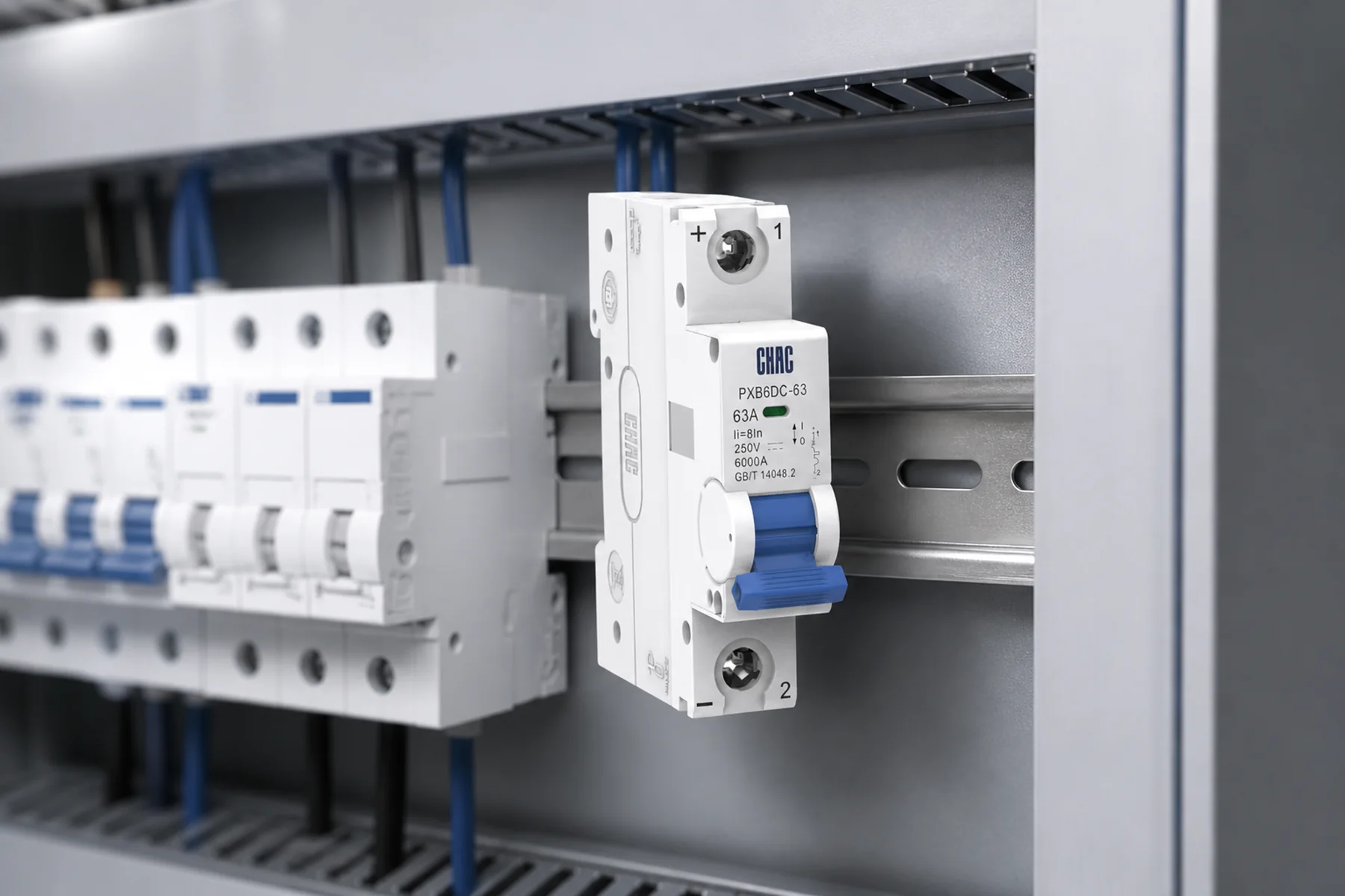
The durable rule is simple: match the breaker to the circuit topology, load behavior, and verified installation evidence rather than to one ampere marking. Review the CHAC CQB2-63 miniature circuit breaker and contact the team with your voltage, poles, load profile, fault-current level, panel arrangement, and compliance needs for model-specific selection support.