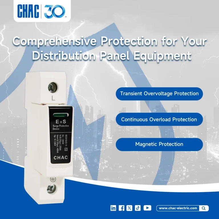
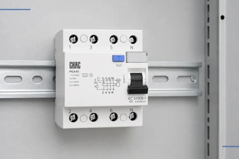
A disconnect selected by its ampere rating alone may solve the wrong problem. Maintenance isolation, switching a running load, and clearing an electrical fault are separate duties; a device that performs one does not automatically perform the others. The distinction becomes especially important when equipment has an inverter, battery, UPS, or separate control supply: opening one switch may leave another source connected to the work area. This guide explains how to specify the required function, check the relevant ratings, and define an isolation boundary that maintenance personnel can verify before work begins.
The short answer is that a disconnect switch separates a circuit or equipment from a source within its declared duty. It does not automatically provide overload or short-circuit protection, and an off-load disconnector must not be assumed to interrupt a running load. For covered US workplace electrical work, OSHA 29 CFR 1910.333 requires disconnection from all electric energy sources and qualified-person verification of the deenergized condition. Start with the equipment’s sources and operating duty, then verify voltage, current, poles, fault-duty evidence, lockout provisions, enclosure, and the installation rules that apply.
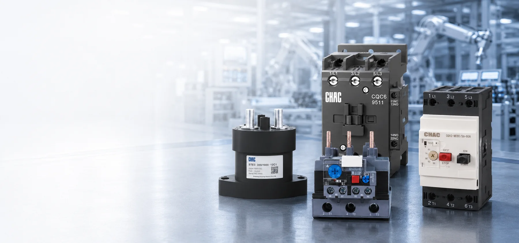
A disconnect switch is a manually or mechanically operated device that separates a circuit or equipment from its source. Regional names include safety switch, isolator, disconnector, switch-disconnector, and local disconnect. Those labels are not performance ratings. Markings and documentation must show whether the product isolates only, interrupts normal load, switches a motor, or combines disconnection with fuses.
Its practical purpose is to give maintenance teams an identifiable boundary between the source and the work area. An OFF handle is only an indication; safe work still requires an approved shutdown, isolation of every relevant energy source, control of stored energy, lockout/tagout, and verification.
What Function Does a Disconnect Switch Perform?
The essential function is disconnection. A circuit breaker instead opens automatically under specified overload or short-circuit conditions; a disconnect may have no trip mechanism. A suitable breaker can sometimes serve as the disconnecting means, but not every disconnect protects a circuit and not every breaker is an effective local isolation point.
A fused disconnect switch adds fuses that may protect the circuit or equipment and support a tested conditional short-circuit rating. A non-fused disconnect relies on separate protection, usually upstream. The designer must identify where protection occurs, whether coordination or current limitation is required, and which component combination was evaluated.
How does isolation differ from load-break duty?
An off-load disconnector establishes isolation after another device removes current. A load-break switch can make and break normal current only within its declared ratings and conditions. Operating an off-load isolator under load can create an arc hazard. State whether operation occurs at no load, at running current, or under a defined motor duty.
For IEC-market procurement, request the exact device’s declared utilization category and its associated voltage and current. Do not assign a motor-switching category from the word “isolator,” a nominal ampere rating, or an enclosure photograph. A published product-standard scope is not evidence of a particular model’s switching duty.
Why does a visible break not complete the isolation process?
Some safety switches expose open blades or provide a viewing window; others use mechanisms and position indication documented by the manufacturer. “Visible blade” and “visible break” may not mean the same thing under every standard or owner specification. Neither replaces verification of the deenergized condition. Ask what is visible, what the indication proves, and whether the mechanism satisfies the project requirement.
| Device type | الوظيفة الأساسية | Selection boundary |
|---|---|---|
| Off-load disconnector or isolator | Establishes isolation after current is removed | Do not operate under load unless expressly rated and marked for that duty |
| Load-break switch | Switches normal current within declared ratings | Confirm isolation suitability separately; a switch-disconnector combines both duties |
| Non-fused disconnect | Provides local switching or isolation as rated | Coordinate with suitable separate overcurrent protection |
| Fused disconnect | Combines disconnection with fuse-based protection | Verify fuse class or type, replacement rules, coordination, and assembly rating |
| Circuit breaker used as a disconnect | Provides automatic protection and may provide disconnection | Confirm isolation marking, instructions, access, lockability, and applicable installation rules |
For the breaker-based option, Schneider Electric’s Fundamental characteristics of a circuit-breaker, updated August 5, 2026, explains that isolation suitability requires the disconnector conditions at the rated voltage and the corresponding marking. Its examples concern Schneider equipment; they do not establish the isolation suitability of an unverified CHAC model.
Blurred roles lead to rejected specifications, damaged contacts, unplanned replacement, or unnecessary spares. Compare engineering, maintenance, and downtime as well as unit price.
Where Do Different Disconnecting-Means Requirements Apply?
For US projects, service disconnecting means, local motor disconnects, HVAC disconnects, and PV disconnects have different installation contexts. Review the locally adopted National Electrical Code edition, equipment instructions, utility requirements where relevant, and the authority having jurisdiction. A downstream general-use switch is not automatically suitable for use as service equipment.
Service equipment also raises grounding and bonding questions. The neutral and equipment-grounding arrangements depend on the system and the disconnect’s location. Ground-electrode resistance is not the same as the effective fault-current path, as this guide to commercial building ground resistance explains.
For industrial motors, review motor duty, supply voltage, starting method, controller location, and switching frequency rather than selecting by continuous amperes alone. A contactor performs control switching but an open contactor is not, by itself, proof of maintenance isolation. This guide to motor switching and isolation separates control duty, isolation, overload protection, and short-circuit protection.
For air-conditioning and refrigeration equipment, review the nameplate, minimum circuit ampacity, maximum overcurrent protection, supply topology, exposure, and required disconnect location together. A weather-resistant box does not prove the correct fuse arrangement, motor duty, pole count, or load-break rating.
PV systems follow a different decision chain. Match maximum DC voltage and current, polarity, conductors opened, and the actual source topology; an AC-only switch cannot be assumed suitable for DC. Rapid shutdown, inverter control, and physical disconnection are distinct functions. Determine which conductors remain energized on each side of the proposed disconnect rather than treating an inverter shutdown indication as an isolation result.
Compliance remains an installation judgment, not a product badge. Confirm the adopted rules, markings, instructions, access, and any required lockable open position. Outside the US, apply the destination country’s rules instead; an IEC product standard does not replace local installation requirements.
Which Ratings Matter When Selecting a Disconnect?
Begin with the electrical basics: system voltage, frequency, phase, continuous current, load profile, ambient temperature, and conductor size. Pole count must match every conductor the design requires to open. Neutral switching is a deliberate engineering decision, especially in multi-source, transfer, or separately derived systems; it should not be inferred from a generic three-pole description.
How do fault current and interrupting duty affect selection?
The ampere rating describes continuous-current capability, not short-circuit survival. Record the available fault current at the installation point and compare it with the short-circuit current rating (SCCR), withstand rating, or tested conditional rating of the exact switch or assembly. A conditional rating may depend on a named fuse class, breaker model, maximum protective-device size, or conductor arrangement. A substitution requires confirmation that the documented combination remains valid.
Fault-current withstand must also be kept separate from interrupting duty. An assembly SCCR describes its suitability for the stated fault conditions, including any required protection; it does not mean the operator may open that fault. Likewise, a load-break or motor-duty rating addresses intended switching of normal current, not automatic interruption of a short circuit. The designated protective device clears faults, while the disconnect performs only the switching duties shown by its markings and instructions.
An industrial control panel’s SCCR is not established by the disconnect alone. Power-circuit components, documented current-limiting combinations, feeder protection, and the evaluation method affect the marked result. Breaker interrupting capacity must also be checked at the applicable voltage and standard: Icu or Icn is not the disconnect’s continuous-current rating. Where selective coordination is required, verify device time-current behavior; high SCCR does not prove selectivity.
How does the installation environment affect reliability?
Specify dust, rain, hose-directed water, chemicals, salt, ultraviolet light, impact, altitude, temperature, and cable entry. IP codes and North American enclosure types are not direct equivalents. Request evidence for the assembled product, including hubs, glands, drains, windows, and operator shafts.
An enclosure rating is not a load-break rating. It describes resistance to stated environmental exposure, while switching duty depends on the switch construction and its declared ratings. An outdoor enclosure can house a device still intended to open only after the load is removed; verify both independently.
Condensation deserves a separate line item. Temperature cycles can cause moisture problems in outdoor enclosures. A manufacturer-approved drain or breather, heater, thermostat, insulation, or revised mounting may be needed. Any addition must preserve the applicable enclosure rating, spacing, and approval; improvised holes can defeat them.
Auxiliary contacts can report status or initiate an interlock. Specify contact form, control rating, sequencing, and mechanical linkage to the main poles. They do not necessarily prove every power contact is open, and control wiring may use another source; show it on the energy-control drawing.
| تطبيق | Design inputs | Evidence or decision to verify | Frequent selection risk |
|---|---|---|---|
| Service entrance | One-line diagram, voltage, current, poles, fault current, jurisdiction | Service suitability, fault-duty data, grounding and bonding arrangement | Treating a downstream safety switch as service equipment |
| Industrial motor | Motor duty, voltage, starting current, controller, switching frequency | Declared motor-switching duty, isolation indication, lockable OFF provision | Confusing the contactor with the isolating and protective devices |
| HVAC equipment | Nameplate data, maximum protection, minimum ampacity, outdoor conditions | Fuse arrangement, motor duty, poles, enclosure, location | Selecting by enclosure appearance or nominal amperes alone |
| PV or battery-connected system | Maximum DC voltage and current, polarity, all sources, operating modes | DC duty, isolation boundaries, conductors opened, manufacturer instructions | Equating inverter OFF or rapid shutdown with complete isolation |
| Maintenance boundary | Every energy source, stored energy, access, written procedure | Lock hardware, contact indication, operating instructions, verification method | Assuming a lockable handle proves zero energy |
| Outdoor or washdown location | Water, dust, chemicals, temperature cycling, cable entries | Enclosure evidence, corrosion data, condensation-control plan | Equating an IP code directly with a North American type rating |
How Do Lockout Rules and Product Standards Affect Selection?
For covered US workplace electrical work on or near exposed deenergized parts, the directly relevant rule is OSHA’s 1910.333 Selection and use of work practices. Paragraph (b)(2)(ii) requires disconnection from all electric energy sources and rejects control-circuit devices as the sole means of deenergizing equipment. Paragraph (b)(2)(iv) requires a qualified person to verify that equipment cannot restart and test the parts employees will be exposed to, including possible induced voltage or unrelated backfeed.
OSHA 1910.147 addresses hazardous-energy control during covered servicing, but electrical exposure addressed by Subpart S has its own requirements. A 1910.147 procedure can satisfy 1910.333(b)(2) only under the conditions stated there, including the specified electrical-hazard, tagging, and verification provisions. Neither rule is a universal consumer installation or licensing law.
How should the isolation boundary account for batteries and inverters?
Use the one-line diagram and exact equipment instructions to list every source that can energize the work area. Depending on the installation, this can include utility supply, PV input, battery connections, a generator or UPS, and separately supplied control circuits. Record the required disconnecting means for each relevant source, the parts still live beyond the boundary, and any stored-energy controls. Opening the AC feeder alone does not establish that an inverter’s DC connections or battery circuit are deenergized.
This source-boundary record is more useful than a single “main OFF” label. It distinguishes stopping power conversion from separating sources and from verifying the condition at the work location. A smart-app OFF command, an open contactor, or a status LED is a control or indication result, not a substitute for the required isolation and verification process. The qualified team must follow the equipment-specific procedure; no universal capacitor waiting time or battery-disconnection sequence can be inferred from the term “disconnect switch.”
The product should support that procedure. Verify padlock quantity and size, group-lockout compatibility, door interlocking, and prevention of closure while locked. One switch may isolate a feeder while leaving another electrical supply, pneumatic accumulator, or gravity hazard active. Define those boundaries before choosing the handle and enclosure.
IEC 60947-3 concerns switches, disconnectors, switch-disconnectors, and fuse-combination units; UL 98 concerns enclosed and dead-front switches. Consult the applicable product-standard edition and exact model documentation. A standard name does not establish load-break category, fault rating, service suitability, or certification. Installation codes, employer work practices, and product standards address different questions.
Unsupported claims can delay approval, invalidate an assembly fault rating, or force field modification. Make technical-document review a design-release checkpoint, and require written approval before a supplier substitutes the switch, fuse, enclosure, or operator mechanism.
How Should You Select a Disconnect for the Installation?
Turn the one-line diagram and operating method into a five-step selection record:
- Define the role. State whether the device is service equipment, a local machine isolator, an HVAC disconnect, a DC disconnect, or a normal-load switch.
- Calculate the electrical duty. Record voltage, frequency, phase, continuous current, poles, motor or DC duty, available fault current, and intended switching frequency.
- Place the protection. Decide whether local fuses are needed for equipment protection, current limitation, coordination, or a tested conditional rating; otherwise document the separate protective device.
- Design the isolation method. Define indication, padlocks, group-lockout needs, auxiliary contacts, every alternate energy source, stored energy, and the verification boundary.
- Verify the complete assembly. Review the enclosure, cable entries, terminals, temperature limits, SCCR evidence, drawings, instructions, and destination-market approvals.
Procurement cost is wider than the switch price. Include engineering review, fuses and spares, enclosure accessories, installation time, inspection risk, planned replacement, and downtime after a nuisance opening or failed component. A non-fused design can reduce spare-part management when suitable separate protection already exists; a fused design may be more economical when current limitation or a documented fault-rating combination avoids a larger redesign.
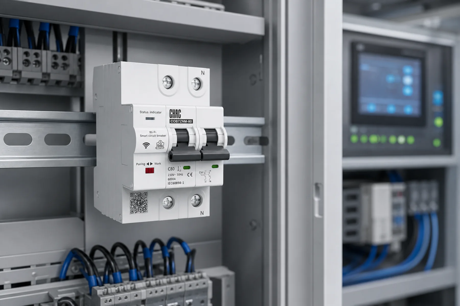
CHAC Electric’s isolating switch page is a starting point for model-document review, not proof of suitability for every load. The CQMG20C Series distribution box page provides an enclosure reference. For both, obtain the exact assembly evidence rather than inferring operating duty or approvals from the product name.
أسئلة متكررة
What is the difference between a disconnect and a breaker?
A disconnect establishes an open point for isolation or rated switching; a breaker automatically opens under specified overcurrent conditions. Some breakers also provide isolation when their markings, instructions, installation, access, and lock provisions satisfy the applicable requirements. Handle appearance alone does not prove interchangeability.
What are the three types of disconnects?
A practical field grouping is off-load disconnectors, load-break switch-disconnectors, and fused disconnects. It is not a universal taxonomy because non-fused, service-rated, motor-use, enclosed, and breaker-based designs overlap. Purchase by required function, standard, and rating rather than category name alone.
What do electricians call disconnects?
Common terms include disconnect switch, safety switch, isolator, disconnector, switch-disconnector, local disconnect, and disconnecting means. Usage varies by region and standard. Reconcile the field name with the product marking and instructions.
When is a fused disconnect required?
Use one when the applicable code, equipment instructions, protection design, or tested fault-rating combination requires fuses at that location. The decision depends on the load, separate protection, available fault current, coordination objective, and exact assembly. Select and document the fuse class or type with the switch.
Can a disconnect switch be used as an emergency shutoff?
Sometimes, if its load rating, accessibility, identification, stop behavior, and installation satisfy the applicable requirements and risk assessment. It does not automatically meet emergency-stop or machine-safety control requirements. Define whether the objective is operational stopping, electrical isolation, emergency switching, or a combination before approval.
Does turning a smart switch off in an app make equipment safe to service?
No. The command may stop the load without isolating every source or controlling stored energy. For covered US workplace electrical work, OSHA 1910.333 requires the prescribed source disconnection, lockout/tagging, and qualified-person verification; an app display is not that verification. Use the equipment-specific energy-control procedure.
Which Sources Define the Relevant Boundaries?
- US Occupational Safety and Health Administration, 1910.333 Selection and use of work practices, particularly paragraphs (b)(2)(ii) and (b)(2)(iv); public text checked October 7, 2026.
- Schneider Electric Electrical Installation Guide, Fundamental characteristics of a circuit-breaker, updated August 5, 2026; manufacturer guidance on isolation marking and breaker ratings, not CHAC model evidence.
- International Electrotechnical Commission, IEC 60947-3, Low-voltage switchgear and controlgear – Part 3; product-standard reference, not evidence of a model’s declared switching category.
- UL Standards & Engagement, UL 98, Standard for Enclosed and Dead-Front Switches; product-standard reference, not an exact-model listing.
The durable rule is to specify the function before the hardware. Identify every source that can energize the work area, decide which loads the device must switch, and establish where fault protection operates. Then verify the exact device and assembly evidence at the project’s voltage, fault conditions, and installation context. A convenient OFF command or a lockable handle cannot replace the required source isolation, stored-energy control, and verification. For a project-specific shortlist, CHAC Electric’s معدات التوزيع الكهربائي resources provide a starting point for discussing the one-line diagram, operating duty, environment, and required documentation. The final selection must support both the installation design and the maintenance procedure.