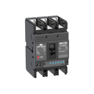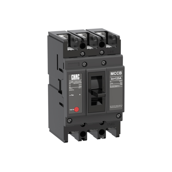
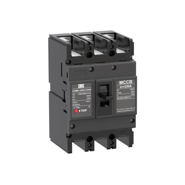
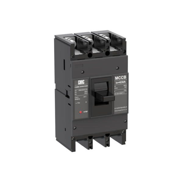
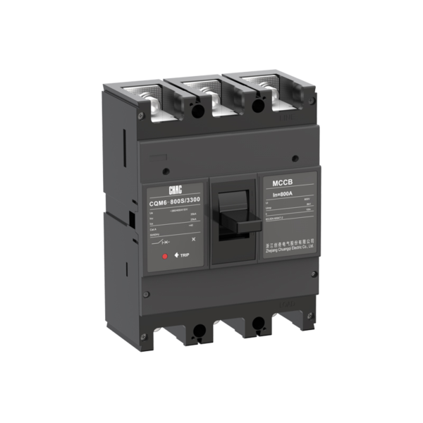
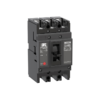
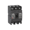
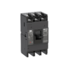
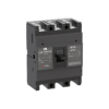
مصنع معدات أصلية لمُقاطِع الدائرة الكهربائية المُقوّس (MCCB) من طراز CQM6 القياسي
ال CQM6 MCCB provides overload and short-circuit protection within its published 16–1600A range. Specification should follow the system voltage, load, conductor coordination, prospective fault current and applicable rules—not the ampere value alone.
مواصفات المنتج
CQM6 is a mccb breaker for AC distribution and protection applications. Its published range covers 16–1600A with 2P / 3P / 4P, depending on frame; CQM6-1600: 3P options. Selection depends on the complete power-system design, including fault level, coordination, conductor ampacity, enclosure conditions and local rules.
The supplied product specification references IEC/EN 60947-1, IEC/EN 60947-2, IEC/EN 60947-3 and IEC/EN 60947-4, together with GB/T 14048.1, .2, .3 and .4. These standard references do not, by themselves, establish certification for a particular order.
الميزات الرئيسية
الاستخدامات النموذجية
Typical applications include commercial, industrial and infrastructure distribution or motor circuits. These are evaluation contexts rather than universal approvals. Confirm the exact frame, voltage, breaking duty, trip unit, accessories and installation method before specification.
طلبات واقتراحات واختيار المرشحين
Use the verified CQM6 values below to create a shortlist, then validate the complete circuit. An MCCB rating does not replace conductor calculations, fault-current analysis, coordination review or local installation requirements.
| نقطة الاختيار | CQM6 reference | ما يجب أن يثبته المشروع |
|---|---|---|
| التيار المقدر | 16–1600A | Design current, conductor ampacity, installation method, temperature and grouping |
| جهد كهربائي | AC 400/415V; CQM6-1600 also lists 660/690V configurations | Supply system and equipment rating |
| أقطاب | 2P / 3P / 4P, depending on frame; CQM6-1600: 3P | Live conductors and neutral treatment |
| Trip / protection | thermal-magnetic trip | Load profile, fault response and coordination |
| قوة الكسر | C/S/M/H/L classes, with Icu up to 100kA for the listed CQM6-1600 660/690V configurations; verify the exact frame and voltage | Prospective short-circuit current at the installation point |
Fixed vs Adjustable Protection
A fixed thermal-magnetic device can suit a stable design, while an adjustable trip unit may help coordination when the project study requires field settings.
Trip Coordination
Compare MCCB Options →
MCCB vs MCB
An MCCB is normally evaluated for higher current, fault duty or accessory flexibility; an MCB may be more suitable for compact final circuits.
Current & Fault Duty
Compare MCCB and MCB →
Icu vs Ics
The saved data for CQM6 lists C/S/M/H/L classes, with Icu up to 100kA for the listed CQM6-1600 660/690V configurations; verify the exact frame and voltage. Match the declared duty to the prospective short-circuit current and continuity objective.
Short-Circuit Study
Review Technical Support →
Pole and Neutral Arrangement
Published pole options are 2P / 3P / 4P, depending on frame; CQM6-1600: 3P. Confirm which conductors must be switched, protected and isolated together.
System Arrangement
View MCCB Range →
دليل طلب الطعام
- State the exact model: CQM6.
- Provide frame and rated current within the published range: 16–1600A.
- Confirm poles: 2P / 3P / 4P, depending on frame; CQM6-1600: 3P.
- Specify the trip unit or protection function: thermal-magnetic trip.
- Provide system voltage, frequency, application, expected fault level, destination market and quantity.
- List required accessories, terminals, documents and any approved OEM/ODM marking or packaging requirements.
فحوصات التثبيت والتنسيق
- Use the exact model drawing and instructions; do not infer terminal positions, supply direction or accessory compatibility from another MCCB.
- Verify conductor material and cross-section against the circuit calculation, terminal data, temperature and grouping.
- Confirm Icu/Ics or DC fault duty, upstream/downstream coordination, enclosure conditions, altitude and clearances.
- Installation, isolation, testing and maintenance must be performed by qualified personnel under applicable rules.
دليل الاختيار

| Product code ① | Extension Code ② | Shell frame grade ③ | Breaking capacity ④ | Operating method ⑤ | Number of poles ⑥ | |||||
|---|---|---|---|---|---|---|---|---|---|---|
| CQM6 | G | 125 | C | P | 4 | |||||
| قاطع الدائرة في الصندوق المطلي | —:Thermal and magnetic protection are not adjustable G:Overload alarm without trip function |
C | S | L | M | H | P: التشغيل عن طريق المحرك Z:Turning handle W.Direct operation |
125A:2P,3P,4P 160A:3P,4P 250A:2P,3P,4P 400A:3P,4P 630A:3P,4P 800A:3P,4P 1250A:3P,4P 1600A:3P |
||
| 125 | 125 | 15/8 | 25/18 | / | / | / | ||||
| 160 | 160 | 25/18 | 35/25 | / | 50/35 | / | ||||
| 250 | 250 | 25/18 | 35/25 | / | 50/35 | / | ||||
| 400 | 400 | / | 35/25 | / | 50/35 | 70/50 | ||||
| 630 | 630 | / | 35/25 | / | 50/35 | 70/50 | ||||
| 800 | 800 | / | 35/25 | / | 50/35 | 70/50 | ||||
| 1250 | 1250 | / | / | / | 50/35 | 70/55 | ||||
| 1600 | 1600 | / | / | 70/20 | 100/35 | 100/50 | ||||
| Trip Unit &Accessories ⑦ | Rated current A ⑧ | Function ⑨ | 4P Option Code ⑩ | Special code ⑪ | |
|---|---|---|---|---|---|
| 300 | 125 أمبير | 2 | A | I | |
| تحدد الرقمة الأولى نوع المقبض. 2:instantaneous detent only 3: مقبض مكرر ملاحظة: الأرقام الأخيرة هي رمز الملحق (انظر جدول الملحقات). |
125 | 16,20,32,40,50,63,80,100,125 | 1: لتوزيع الطاقة 2: لحماية المحرك |
أ: النقطة N غير محمية ولا يمكن الجمع بينها. B:N-pole غير مأمون ويمكن الجمع بينهما C:N-pole مأمون ويمكن الجمع بينهما D:N-pole مأمون ولا يمكن الجمع بينهما |
I:Overload alarm non trip function |
| 160 | 16,20,32,40,50,63,80,100,125,140,160 | ||||
| 250 | 100,125,140,160,180,200,225,250 | ||||
| 400 | 250,315,350,400 | ||||
| 630 | 250,315,350,400,500,630 | ||||
| 800 | 500,630,700,800 | ||||
| 1250 | 800,1000,1250 | ||||
| 1600 | 800,1000,1250,1400,1500,1600 | ||||
| Accessory Voltage ⑫ | Motorized operating voltage ⑬ | Installation ⑭ | Terminal Block Option ⑮ | |||
|---|---|---|---|---|---|---|
| سؤال 1 | D1 | Q | 2 | |||
| Undervoltage detent Q1:AC220V Q2:AC240V Q3:AC380V Q4:AC415V | Shunt release F1:AC220V F2:AC380V F3:DC110V F4:DC24V | Auxiliary alarm J1:AC125V J2:AC250V J3:DC125V J4:DC24V | CD1 التشغيل الكهربائي D1: AC220V D2:AC230V D3: AC380V D4:AC400V |
CD2 Electrical Operation D5:AC230V D6:AC110V D7:DC220 D8:DC110 D9:AC110–240V D10:DC100–220V | Q:Front of plate H:Rear of plate C:Inserted | 1:Noinstitution 2: التثبيت |
| ملاحظة: عند تحديد تشغيل المحرك، يرجى الرجوع إلى الملحقات الخارجية لمعرفة الجهدين المطبقين على تشغيل المحرك. | ||||||
قائمة الملحقات
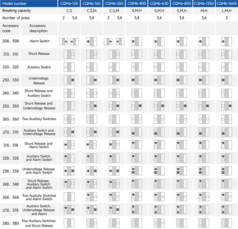
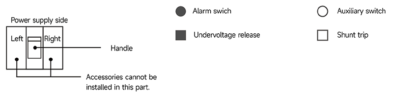
CHAC offers a right-side auxiliary switch, a left-side shunt release and a left-side undervoltage release.
For accessory codes 220, 320, 240, 340, 270 and 370, the auxiliary switch can provide two contact pairs. Specify this requirement when ordering.
For accessory codes 250 and 350, the shunt release and undervoltage release on frames 400 and above are available only for 3-pole circuit breakers.
المواصفات الفنية الرئيسية
| رقم النموذج | CQM6-125 | CQM6-160 | |||||
|---|---|---|---|---|---|---|---|
| التيار المقدر على مستوى الإطار Inm(A) | 125 | 160 | |||||
| عدد الأقطاب | 2,3,4 | 3,4 | |||||
| Rated current In(A),at 40°C,50°C,55°C | 16,20,25,32,40,50,63,80,100,125 | 16,20,25,32,40,50,63,80,100,125,140,160 | |||||
| الجهد التشغيلي المقدر Ue (V)، التيار المتردد 50/60 هرتز | 400/415 | 400/415 | |||||
| جهد العزل المقدر Ui (V) | 800 | 800 | |||||
| الجهد المقاوم للتأثير الكهربائي Uimp (KV) | 8 | 8 | |||||
| تصنيف قدرة التكسير | C | S | C | S | M | ||
| قدرة كسر المقاومة عند القصور في التيار Icu/Ics (kA) | AC400/415V | 15/8 | 25/18 | 25/18 | 35/25 | 50/35 | |
| فئة الانتقائية | A | A | A | A | A | ||
| Number of operating cycles(cycle) | أفتح | 6000 | 6000 | ||||
| إيقاف التشغيل | 10000 | 10000 | |||||
| آليات الرحلات وأنواع الحماية | رحلة مغناطيسية | حماية توزيع الطاقة | ● | ● | ● | ● | ● |
| حماية المحرك | ● | ● | ● | ● | ● | ||
| رحلة الحرارية المغناطيسية | حماية توزيع الطاقة | ● | ● | ● | ● | ● | |
| حماية المحرك | ● | ● | ● | ● | ● | ||
| مستلزمات | الاتصالات الإضافية | ● | ● | ● | ● | ● | |
| الاتصالات في حالة الطوارئ | ● | ● | ● | ● | ● | ||
| قطع الشق | ● | ● | ● | ● | ● | ||
| مستشعر انخفاض الجهد | ● | ● | ● | ● | ● | ||
| آلية التشغيل اليدوية | ● | ● | ● | ● | ● | ||
| آلية تشغيل ميكانيكية | ● | ● | ● | ● | ● | ||
| توصيلات الخلفية | ● | ● | ● | ● | ● | ||
| تم إدخاله | ● | ● | ● | ● | ● | ||
| غطاء التوصيل | ● | ● | ● | ● | ● | ||
| التقسيم بين المراحل | ● | ● | ● | ● | ● | ||
| المنتجات المشتقة | مخصصة للمقاييس الكهربائية المدفوعة مقدماً | ● | ● | ● | ● | ● | |
| إنذار الزائد دون حدوث انقطاع | – | – | ● | ● | ● | ||
| Overall dimensions (mm) (a–b–c–ca) | 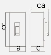 |
3 P | 75×130×68×91 | 90×155×70×95 | 90×155×85 ×109 | ||
| 4 P | 100×130×68×91 | 120×155×70×95 | 120×155×85 ×109 | ||||
Note: ● indicates an available optional accessory; – indicates that the accessory is not available.
المواصفات الفنية الرئيسية
| رقم النموذج | CQM6-250 | CQM6-400 | CQM6-630 | ||||||||
|---|---|---|---|---|---|---|---|---|---|---|---|
| التيار المقدر على مستوى الإطار Inm(A) | 250 | 400 | 630 | ||||||||
| عدد الأقطاب | 2,3,4 | 3,4 | 3,4 | ||||||||
| Rated current In(A),at 40°C,50°C,55°C | 100,125,140,160,180,200,225,250 | 250,315,350,400 | 250,315,350,400,500,630 | ||||||||
| الجهد التشغيلي المقدر Ue (V)، التيار المتردد 50/60 هرتز | 400/415 | 400/415 | 400/415 | ||||||||
| جهد العزل المقدر Ui (V) | 800 | 800 | 800 | ||||||||
| الجهد المقاوم للتأثير الكهربائي Uimp (KV) | 8 | 8 | 8 | ||||||||
| تصنيف قدرة التكسير | C | S | M | S | M | H | S | M | H | ||
| قدرة كسر المقاومة عند القصور في التيار Icu/Ics (kA) | AC400/415V | 25/18 | 35/25 | 50/35 | 35/25 | 50/35 | 70/50 | 35/25 | 50/35 | 70/50 | |
| فئة الانتقائية | A | A | A | A | A | A | A | A | A | ||
| Number of operating cycles (cycle) |
أفتح | 6000 | 3000 | 3000 | |||||||
| إيقاف التشغيل | 10000 | 8000 | 8000 | ||||||||
| آليات الرحلات وأنواع الحماية | رحلة مغناطيسية | حماية توزيع الطاقة | ● | ● | ● | ● | ● | ● | ● | ● | ● |
| حماية المحرك | ● | ● | ● | ● | ● | ● | ● | ● | ● | ||
| رحلة الحرارية المغناطيسية | حماية توزيع الطاقة | ● | ● | ● | ● | ● | ● | ● | ● | ● | |
| حماية المحرك | ● | ● | ● | ● | ● | ● | ● | ● | ● | ||
| مستلزمات | الاتصالات الإضافية | ● | ● | ● | ● | ● | ● | ● | ● | ● | |
| الاتصالات في حالة الطوارئ | ● | ● | ● | ● | ● | ● | ● | ● | ● | ||
| قطع الشق | ● | ● | ● | ● | ● | ● | ● | ● | ● | ||
| مستشعر انخفاض الجهد | ● | ● | ● | ● | ● | ● | ● | ● | ● | ||
| آلية التشغيل اليدوية | ● | ● | ● | ● | ● | ● | ● | ● | ● | ||
| آلية تشغيل ميكانيكية | ● | ● | ● | ● | ● | ● | ● | ● | ● | ||
| توصيلات الخلفية | ● | ● | ● | ● | ● | ● | ● | ● | ● | ||
| تم إدخاله | ● | ● | ● | ● | ● | ● | ● | ● | ● | ||
| غطاء التوصيل | ● | ● | ● | ● | ● | ● | ● | ● | ● | ||
| التقسيم بين المراحل | ● | ● | ● | ● | ● | ● | ● | ● | ● | ||
| المنتجات المشتقة | مخصصة للمقاييس الكهربائية المدفوعة مقدماً | ● | ● | ● | ● | ● | ● | ● | ● | ● | |
| إنذار الزائد دون حدوث انقطاع | ● | ● | ● | ● | ● | ● | ● | ● | ● | ||
| الأبعاد الكلية (مم) (أ-ب-ج-كأ) | |
3 P | 105×165×70×95 | 105×165×93×118 | 140×257×107×156 | 140×257×107×156 | |||||
| 4 P | 140×165×70×95 | 140×165×93×118 | 185×257×107×156 | 185×257×107×156 | |||||||
Note: ● indicates an available optional accessory; – indicates that the accessory is not available.
المواصفات الفنية الرئيسية
| رقم النموذج | CQM6-800 | CQM6-1250 | CQM6-1600 | |||||||
|---|---|---|---|---|---|---|---|---|---|---|
| التيار المقدر على مستوى الإطار Inm(A) | 800 | 1250 | 1600 | |||||||
| عدد الأقطاب | 3,4 | 3,4 | 3 | |||||||
| Rated current In(A),at 40°C,50°C,55°C | 500,630,700,800 | 800,1000,1250 | 800,1000,1250,1400,1500,1600 | |||||||
| الجهد التشغيلي المقدر Ue (V)، التيار المتردد 50/60 هرتز | 400/415 | 400/415 | 400/415V | 660/690V | ||||||
| جهد العزل المقدر Ui (V) | 800 | 1000 | 1000 | |||||||
| الجهد المقاوم للتأثير الكهربائي Uimp (KV) | 8 | 12 | 12 | |||||||
| تصنيف قدرة التكسير | S | M | H | M | H | L | M | H | ||
| قدرة كسر المقاومة عند القصور في التيار Icu/Ics (kA) | AC400/415V | 35/25 | 50/35 | 70/50 | 50/35 | 70/55 | 70/20 | 100/35 | 100/50 | |
| فئة الانتقائية | A | A | A | A | A | A | A | A | ||
| Number of operating cycles (cycle) |
أفتح | 1000 | 1000 | 500 | ||||||
| إيقاف التشغيل | 3000 | 3000 | 3000 | |||||||
| آليات الرحلات وأنواع الحماية | رحلة مغناطيسية | حماية توزيع الطاقة | ● | ● | ● | ● | ● | ● | ● | ● |
| حماية المحرك | ● | ● | ● | ● | ● | ● | ● | ● | ||
| رحلة الحرارية المغناطيسية | حماية توزيع الطاقة | ● | ● | ● | ● | ● | ● | ● | ● | |
| حماية المحرك | ● | ● | ● | ● | ● | ● | ● | ● | ||
| مستلزمات | الاتصالات الإضافية | ● | ● | ● | ● | ● | ● | ● | ● | |
| الاتصالات في حالة الطوارئ | ● | ● | ● | ● | ● | ● | ● | ● | ||
| قطع الشق | ● | ● | ● | ● | ● | ● | ● | ● | ||
| مستشعر انخفاض الجهد | ● | ● | ● | ● | ● | ● | ● | ● | ||
| آلية التشغيل اليدوية | ● | ● | ● | ● | ● | ● | ● | ● | ||
| آلية تشغيل ميكانيكية | ● | ● | ● | ● | ● | ● | ● | ● | ||
| توصيلات الخلفية | ● | ● | ● | ● | ● | ● | ● | ● | ||
| تم إدخاله | ● | ● | ● | ● | ● | ● | ● | ● | ||
| غطاء التوصيل | ● | ● | ● | ● | ● | ● | ● | ● | ||
| التقسيم بين المراحل | ● | ● | ● | ● | ● | ● | ● | ● | ||
| المنتجات المشتقة | مخصصة للمقاييس الكهربائية المدفوعة مقدماً | ● | ● | ● | ● | ● | ● | ● | ● | |
| إنذار الزائد دون حدوث انقطاع | ● | ● | ● | ● | ● | ● | ● | ● | ||
| Overall dimensions (mm) (a–b–c–ca) | |
3 P | 210×275×113×162 | 210×275×113×162 | 210×268×161×240 | |||||
| 4 P | 280×275×113×162 | 280×275×113×162 | ||||||||
Note: ● indicates an available optional accessory; – indicates that the accessory is not available.
خصائص التشغيل
The following table gives the inverse-time operating characteristics for distribution protection with all poles energised at an ambient temperature of +40°C, without humidity compensation.
| اختبار التصنيف الحالي | إعداد متعددة الحالات الحالية | الوقت التقليدي | الوضع الأولي |
|---|---|---|---|
| في ≤63 <In | |||
| الحالة التقليدية بدون انقطاع التيار | 1.05 | ≥1 ساعة ≥2 ساعة | دولة رائعة |
| الحالة التقليدية لتسريع التيار الكهربائي | 1.30 | <1ساعة <2ساعة | الوضع الساخن |
The following table gives the inverse-time operating characteristics for motor protection with all poles energised at an ambient temperature of +40°C, without humidity compensation.
| اختبار التصنيف الحالي | إعداد متعددة الحالات الحالية | الوقت التقليدي | الوضع الأولي |
|---|---|---|---|
| في ≤800 | |||
| الحالة التقليدية بدون انقطاع التيار | 1.0 | ≥2 ساعة | دولة رائعة |
| الحالة التقليدية لتسريع التيار الكهربائي | 1.2 | <2 ساعة | الوضع الساخن |
The operating-characteristics reference gives an instantaneous trip current setting of 10In for distribution protection. Confirm the applicable trip-unit setting for the ordered configuration.
The operating-characteristics reference gives an instantaneous trip current setting of 12In for motor protection.
The stated accuracy of the instantaneous trip current setting is 20% of the setting value.
CQM6-125 Operating Characteristic Curve
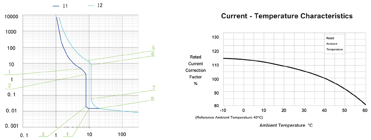
CQM6-160 Operating Characteristic Curve
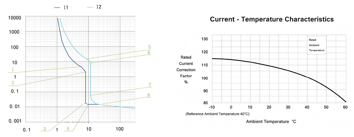
CQM6-250 Operating Characteristic Curve
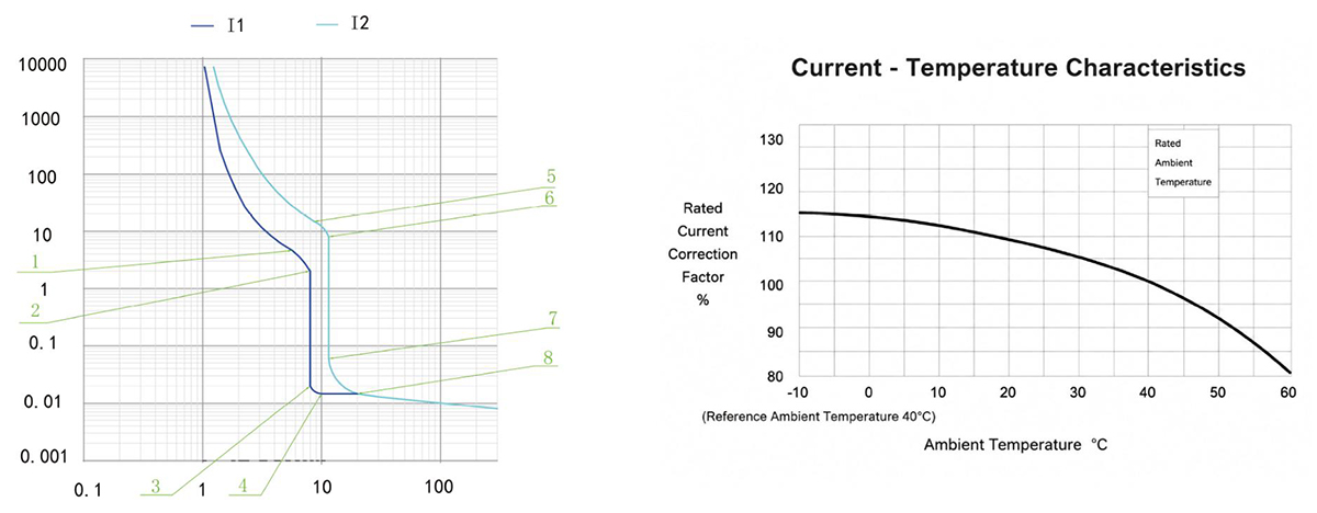
CQM6-400 / 630 Operating Characteristic Curve
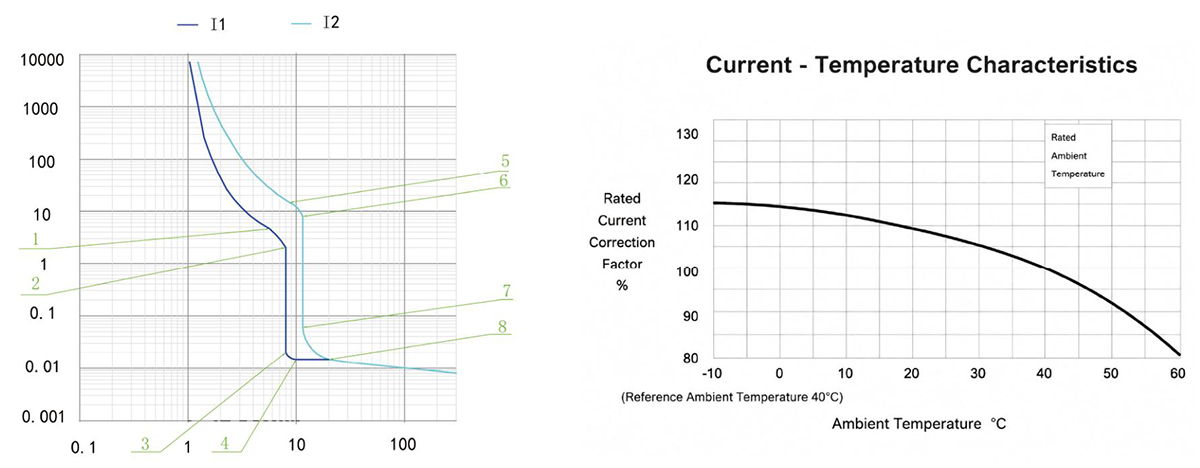
CQM6-800 Operating Characteristic Curve
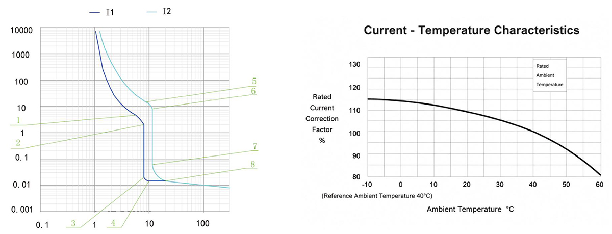
CQM6-1250 Operating Characteristic Curve
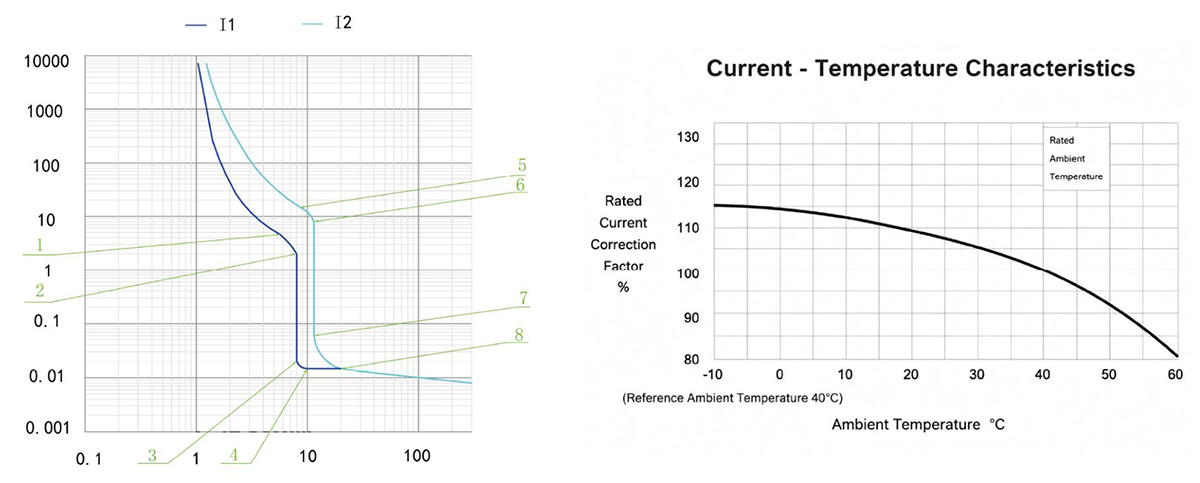
CQM6-125~1250 Outline and Installation Dimensions(mm)
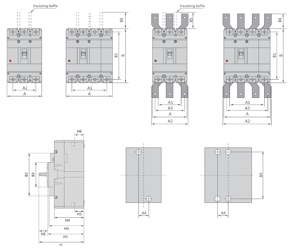
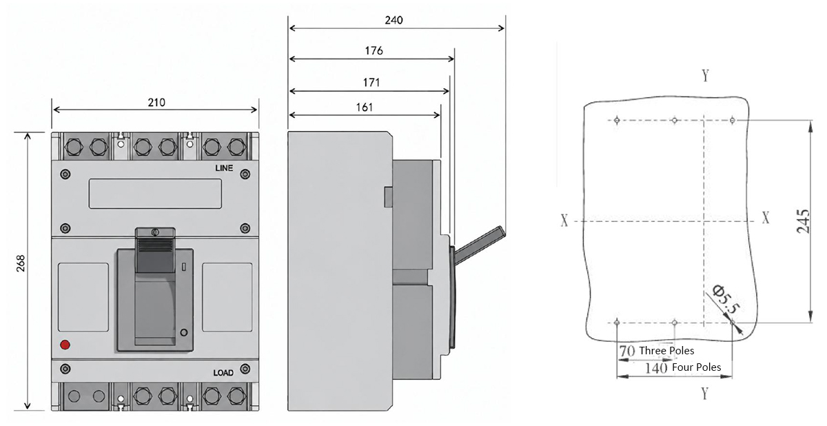
CQM6-1600 Outline and Installation Dimensions(mm)
| قاطع الدائرة في الصندوق المطلي | الابعاد الكلية | Installation dimensions | Boit | |||||||||||||||||||||
|---|---|---|---|---|---|---|---|---|---|---|---|---|---|---|---|---|---|---|---|---|---|---|---|---|
| A | A1 | A2 | A3 | B | B1 | B2 | B3 | B5 | B6 | H | H1 | H2 | H3 | H4 | H5 | H6 | A4 | B4 | ||||||
| 3P | 4P | 3P | 4P | 3P | 4P | 3P | 4P | |||||||||||||||||
| CQM6-125CSM | 75 | 100 | 50 | 75 | – | – | – | – | 130 | 114 | 85 | 50 | 48 | – | 91 | 73.4 | 2.4 | 68 | 61 | 23.9 | 24 | 25 | 111 | M6 |
| CQM6-160CS | 90 | 120 | 60 | 90 | – | – | – | – | 155 | 134 | 103 | 50 | 48 | – | 95 | 75.5 | 2.1 | 70 | 62 | 24 | 24.8 | 30 | 132 | M8 |
| CQM6-160M | 90 | 120 | 60 | 90 | – | – | – | – | 155 | 134 | 103 | 50 | 48 | – | 109.5 | 90 | 2.1 | 85 | 76.5 | 23.6 | 25 | 30 | 132 | M8 |
| CQM6-250CS | 105 | 140 | 70 | 105 | – | – | – | – | 165 | 144 | 102 | 50 | 97 | – | 95 | 74.2 | 2.7 | 70 | 61.4 | 22.3 | 23.1 | 35 | 126 | M8 |
| CQM6-250M | 105 | 140 | 70 | 105 | – | – | – | – | 165 | 144 | 102 | 50 | 95 | – | 118.5 | 97.7 | 2.7 | 93.4 | 84.8 | 22.9 | 23.3 | 35 | 126 | M8 |
| CQM6-400SMH | 140 | 185 | 70 | 132 | 140 | 196 | 112 | 168 | 257 | 230 | 179 | 90 | 103 | 42 | 156 | 111.7 | 3.5 | 107.5 | 99.5 | 30.9 | 32.4 | 44 | 194 | M10 |
| CQM6-630SMH 400A | 140 | 185 | 88 | 132 | 140 | 196 | 112 | 168 | 257 | 230 | 179 | 90 | 103 | 42 | 156 | 111.7 | 3.5 | 107.5 | 99.5 | 30.9 | 32.4 | 44 | 194 | M10 |
| CQM6-630SMH 630A | 140 | 185 | 88 | 132 | 140 | 196 | 112 | 168 | 257 | 230 | 179 | 90 | 103 | 42 | 156 | 111.7 | 3.5 | 107.5 | 99.5 | 33.2 | 34 | 44 | 194 | M10 |
| CQM6-800SMH 630A | 210 | 280 | 140 | 210 | 180 | 250 | 140 | 210 | 275 | 243 | 192 | 90 | 103 | 87 | 162.5 | 118 | 2.7 | 113.4 | 105.5 | 28.3 | 30.4 | 70 | 242.5 | M12 |
| CQM6-800SMH 800A | 210 | 280 | 140 | 210 | 180 | 250 | 140 | 210 | 275 | 243 | 192 | 90 | 103 | 87 | 162.5 | 118 | 2.7 | 113.4 | 105.5 | 29 | 32.6 | 70 | 242.5 | M12 |
| CQM6-1250SMH | 210 | 280 | 140 | 210 | 180 | 250 | 140 | 210 | 275 | 243 | 192 | 90 | 103 | 87 | 162.5 | 118 | 2.7 | 113.4 | 105.5 | 31.3 | 34.4 | 70 | 242.5 | M10 |
| CQM6-1600LMH | 210 | – | 140 | – | – | – | – | – | 268 | 240 | 118 | 97 | 110 | – | 240 | 171 | 5 | 161 | 150 | 33 | 34 | 70 | 245.0 | M10 |
لماذا تختار CHAC
مع خبرة تصنيع تزيد عن 30 عامًا، وأكثر من 1100 موظف، وأكثر من 100 مليون عمود
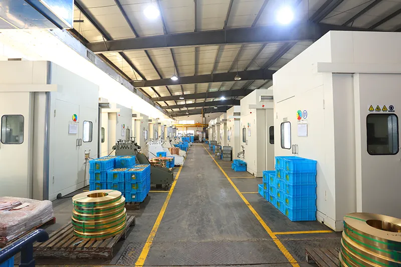
بفضل طاقتها الإنتاجية السنوية ونظام الإنتاج الآلي 90%، توفر شركة CHAC طاقة إنتاجية مستقرة ومعايير صارمة
مراقبة الجودة لعملاء OEM/ODM العالميين. يدعم نظام التصنيع الداخلي الخاص بنا على المدى الطويل
تعاون مع العلامات التجارية الكهربائية والمستوردين والموزعين.

30+
سنوات الخبرة
متخصص في تصنيع المعدات الكهربائية منخفضة الجهد

1100+
الموظفين
فريق محترف يضمن جودة ثابتة والتسليم

١٠٠ مليون+
السعة السنوية للأعمدة
قدرة إنتاجية واسعة النطاق لتلبية الطلب العالمي

90%
الإنتاج الآلي
الأتمتة المتقدمة لتحقيق كفاءة واتساق عاليين
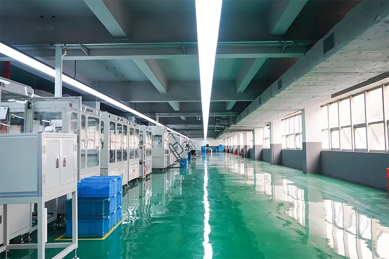
خط التجميع الآلي

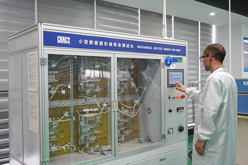
مختبر اختبار
حقن وختم
فحص الجودة



نظام صارم لمراقبة الجودة يضمن أن كل منتج يلبي المعايير العالمية.
ما الذي يمكننا تخصيصه؟
For CQM6 projects, CHAC can review private-label marking, packaging, approved appearance options, published 16–1600A electrical configurations and technical-document requirements. Requests outside the published range are subject to engineering evaluation, testing, minimum order quantity and project feasibility.

حَظِيرة
تصميم
أحجام وحاويات مخصصة وهياكل وتفاصيل تركيب.
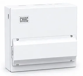

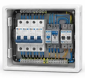
داخلي
إعدادات
خيارات مرنة لتخطيط داخلي وترتيب المكونات.

العلامة التجارية و
شعار
شعارات العلامة التجارية الخاصة، ولوحات الأسماء، وتحديد الهوية التجارية.
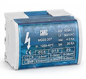

تعبئة وتغليف
تصميم
علب مخصصة، وملصقات، وأدلة، وحلول تغليف.

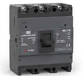
كهربائي
إعدادات
إعداد كهربائي مخصص بناءً على متطلبات التطبيق.

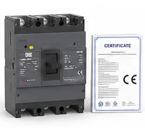
شهادة
دعم
دعم معايير السوق المستهدفة ومتطلبات الامتثال.
تنزيل
قاطع الدائرة المقولبة من سلسلة CQM6
نظرة عامة كاملة على مكونات كهربائية منخفضة الجهد ومرجع لاختيار المنتج.
هل تحتاج إلى وثائق فنية؟
اتصل بنا للحصول على أوراق البيانات، والشهادات، والرسومات، وإرشادات الاختيار، أو دعم مشاريع OEM/ODM.
CQM6 Product FAQ
What is the CQM6 MCCB used for?
The CQM6 is specified for overload and short-circuit protection in AC systems at the voltage listed for the ordered frame within the published 16–1600A range. Suitability depends on the fault study, conductor coordination, enclosure and local rules.
How does the CQM6 molded case circuit breaker work?
The protection mechanism responds to the fault conditions stated for this model: overload and short-circuit protection. Trip behaviour, settings and interruption duty must be checked against the ordered frame and product instructions.
How do I choose the CQM6 rated current and poles?
Start with the design current and conductor calculation, then choose a published current within 16–1600A and poles from 2P / 3P / 4P, depending on frame; CQM6-1600: 3P. Neutral treatment, fault level, ambient conditions and coordination also need review.
What breaking capacity should I check on the CQM6?
Use the declared C/S/M/H/L classes, with Icu up to 100kA for the listed CQM6-1600 660/690V configurations; verify the exact frame and voltage for the exact frame, voltage and configuration. The prospective short-circuit current at the installation point must be within the applicable duty; a larger ampere value alone is not a selection rule.
Can the CQM6 replace an MCB or an earth-leakage device?
An MCCB is not automatically a like-for-like replacement. The CQM6 provides overload and short-circuit protection; residual-current protection, DC interruption, adjustable settings and other functions must be confirmed separately from the project requirement.
How should the CQM6 be installed and tested?
Use only the exact model drawing, terminal identification and accessory instructions. A qualified person should verify isolation, conductor size, torque, clearances, settings, fault duty and functional tests before energising the circuit.
Confirm the Right CQM6 Configuration
Send the frame, rated current, poles, protection function, system voltage, expected fault level, destination market and quantity. CHAC will review the request against the published model range.