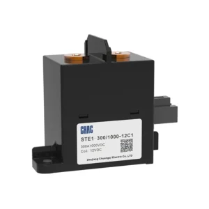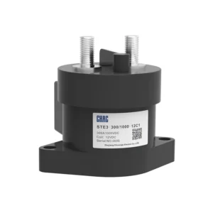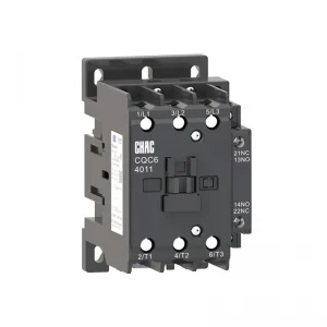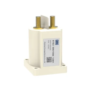


Contactor de CA de alta resistencia de la serie CQC1 y accesorios
El Contactor de CA de alta resistencia de la serie CQC1 y accesorios is a CHAC AC contactor for remote switching and motor control. The page keeps the model-specific technical table and original product images so buyers can verify voltage, current, configuration, mounting and applicable standards before ordering. Final suitability depends on the complete circuit, installation method and destination-market rules.
Descripción del producto
CQC1 Series High-Duty AC Contactor and Accessories is a AC contactor intended for remote switching and motor control. The current product record identifies it for motor starters, HVAC and automation panels. Use the exact model variant and preserved technical source as the basis for procurement rather than assuming that every family member has the same rating.
Verified source summary: Model and Meaning Note 1: 09A~95A is in the form of auxiliary contact, and 115A~800Aisconventional without auxiliary10 indicates three normally open main contacts and one normally open auxiliary contact (32A and below)01 represents three normally open main contacts and one normally closed auxiliary contact (32A and below)11 represents three normally open main contacts, one normally open and one normally closed auxili
Características clave
Aplicaciones típicas
Typical use can include motor starters, HVAC and automation panels when the project confirms system voltage, current, fault or surge exposure, conductor and enclosure requirements, and the selected variant’s installation instructions. This page does not replace the project design or the authority having jurisdiction.
Guía de Solicitudes y Selección
Use the following decision points with the preserved model data. Product-family descriptions explain intent, but the exact technical table controls the ordered variant.
| Punto de selección | Contactor de CA de alta resistencia de la serie CQC1 y accesorios | Lo que el proyecto debe confirmar |
|---|---|---|
| Solicitud | AC Contactor projects | Confirm the actual system and environment |
| Selection basis | remote switching and motor control | Use the exact model and technical table |
| Instalación | Follow the model instructions | Check mounting, clearances and termination |
| Cumplimiento | Use the listed standard where applicable | Verify edition, scope and destination rules |
| Adjacent product | Evaluate the related CHAC family where function differs | Do not substitute without engineering review |
Function
remote switching and motor control
Match the protection or switching function to the system.
Configuración
Model-specific options
Confirm current, voltage, poles, terminals or accessories from the table.
Instalación
Mechanical and electrical fit
Check enclosure, mounting, wiring space and maintenance access.
Project evidence
Documents and test records
Retain the approved drawing, technical sheet and commissioning record.
Guía de pedidos
- State the exact model and variant.
- Provide the system voltage, current, frequency and load or protection function.
- Confirm mounting, terminals, accessories, enclosure and environmental conditions.
- Share quantity, destination market and required technical documents.
Comprobaciones de Instalación y Coordinación
- Verify the model’s ratings and connection arrangement against the project drawings.
- Check conductor, busbar, enclosure, clearances and tightening requirements using the product documentation.
- Coordinate upstream and downstream protection or control devices where applicable.
- Use qualified personnel for installation, testing, isolation and maintenance.
Model and Meaning

Note 1: 09A~95A is in the form of auxiliary contact, and 115A~800Aisconventional without auxiliary10 indicates three normally open main contacts and one normally open auxiliary contact (32A and below)01 represents three normally open main contacts and one normally closed auxiliary contact (32A and below)11 represents three normally open main contacts, one normally open and one normally closed auxiliary contact (40~95A).
Appearance and installation dimensions
CQC1-09 12、18、25、32
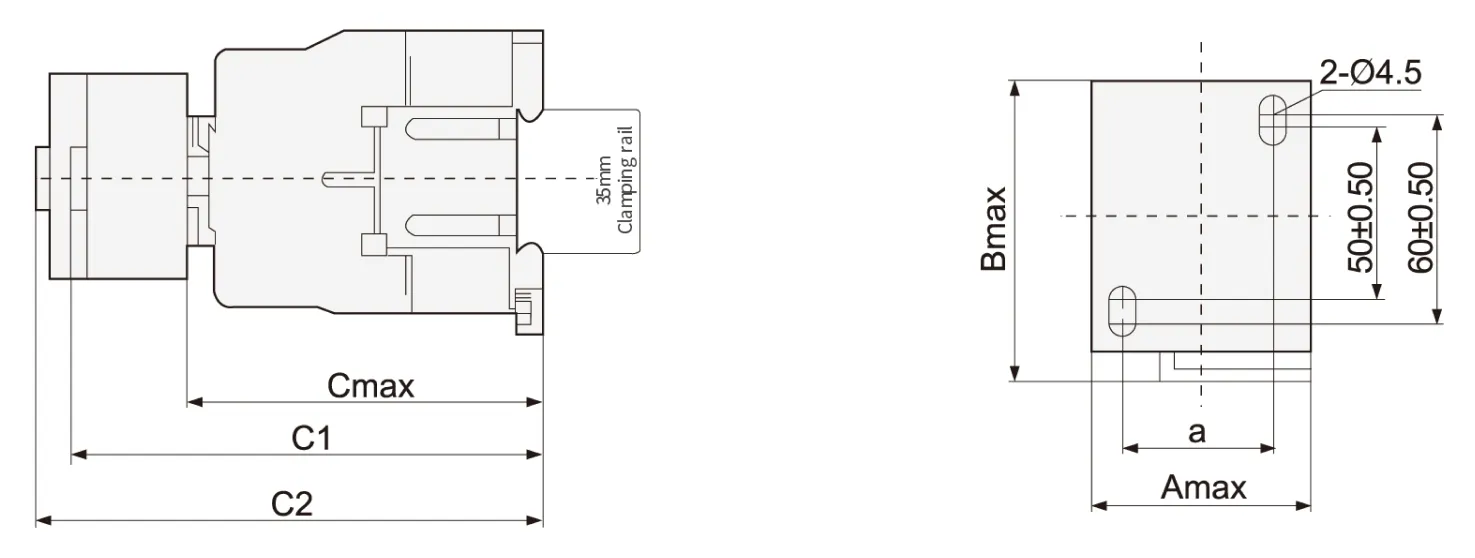
| Contactor model | Amax | Bmax | Cmax | a | C1 | C2 |
| CQC1-09、12 | 47 | 76 | 82 | 35±0.50 | 113 | 133 |
| CQC1-18 | 87 | 118 | 138 | |||
| CQC1-25 | 57 | 86 | 95 | 40±0.50 | 126 | 146 |
| CQC1-32 | 100 | 131 | 151 |
Note: C1:CQC1+F4 C2:CQC1+S4
CQC1-40、50、65、80、95
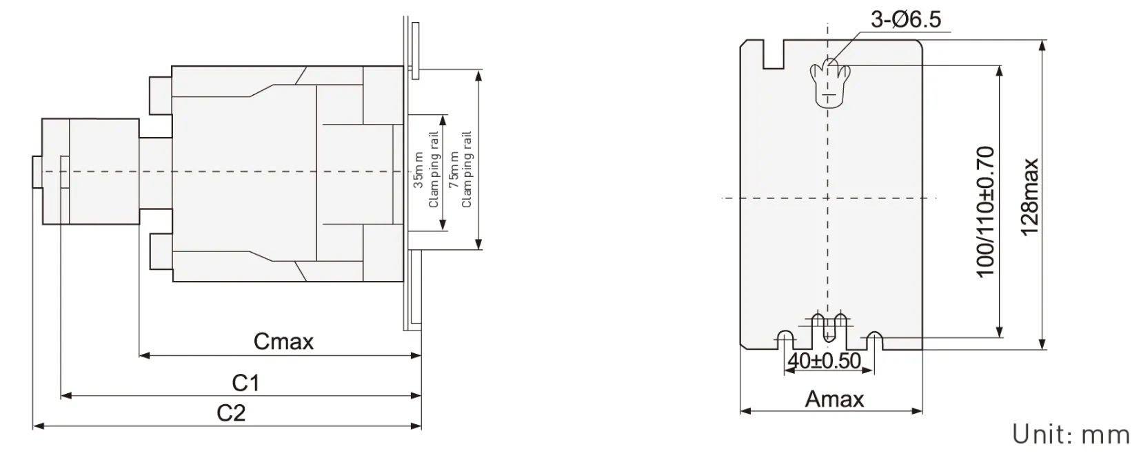
| Contactor model | Amax | Cmax | C1 | C2 |
| CQC1-4011-6511 | 77 | 116 | 145 | 165 |
| CQC1-8011~9511 | 87 | 127 | 175 | 195 |
Note:C1:CQC1+F4 C2:CQC1+S4
C0C1-115~330 overall dimensions and installation dimensions [tolerance: ± 1mm]

| CQC1 | a | P | Q | Q1 | S | Φ | f | b | b1 | M | N | c | L | G | H | Φ1 | G1 | Z | Y | X1 | |
| ≤500V | >500V | ||||||||||||||||||||
| 115 | 163.5 | 37 | 29.5 | 60 | 20 | M6 | 131 | 162 | 137 | 147 | 124 | 171 | 107 | 80 | 120-106 | 6.5 | 106 | 13.5 | 44 | 10 | 15 |
| 150 | 163.5 | 40 | 26 | 57.5 | 20 | M8 | 131 | 170 | 137 | 150 | 124 | 171 | 107 | 80 | 120-106 | 6.5 | 106 | 13.5 | 44 | 10 | 15 |
| 185 | 168.5 | 40 | 29 | 59.5 | 20 | M8 | 130 | 174 | 137 | 154 | 127 | 181 | 113.5 | 80 | 120-106 | 6.5 | 111 | 13.5 | 44 | 10 | 15 |
| 225 | 168.5 | 48 | 21 | 51.5 | 25 | M10 | 130 | 197 | 137 | 172 | 127 | 181 | 113.5 | 80 | 120-106 | 6.5 | 111 | 13.5 | 44 | 10 | 15 |
| 265 | 205 | 48 | 39 | 66.5 | 25 | M10 | 147 | 203 | 145 | 180 | 147 | 213 | 141 | 96 | 120-106 | 6.5 | 140 | 20.5 | 38 | 10 | 15 |
| 330 | 213 | 48 | 43 | 74 | 25 | M10 | 147 | 209 | 145 | 184 | 158 | 219 | 145 | 96 | 120-106 | 6.5 | 154.5 | 20.5 | 38 | 10 | 15 |
Note: f is the space required for coil replacement
X1 is the minimum electrical clearance [Flying Fox distance)the same as below
CQC1-400-500 overall dimensions and installation dimensions(tolerance: ± 1mm)
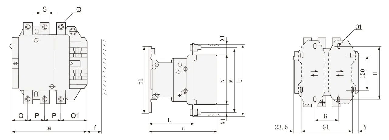
| CQC1 | a | P | Q | Q1 | S | Φ | f | b | b1 | M | N | c | L | G | G1 | Φ1 | H | Y | X1 | |
| ≤500V | >500V | |||||||||||||||||||
| 400 | 213 | 48 | 43 | 74 | 25 | M10 | 151 | 206 | 209 | 181 | 158 | 219 | 145 | 80(66-102) | 170(156-192) | 8.5 | 180 | 19.5 | 15 | 20 |
| 500 | 233 | 46 | 46 | 77 | 30 | M10 | 169 | 238 | 209 | 208 | 172 | 232 | 146 | 80(66-102) | 170(156-210) | 8.5 | 180 | 39.5 | 15 | 20 |
CQC1-630-800 overall dimensions and installation dimensions(tolerance: ± 1mm)
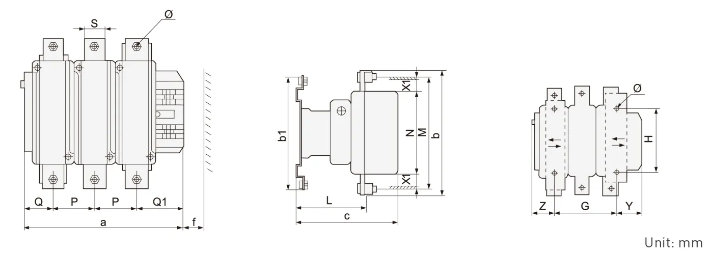
| CQC1 | a | P | Q | Q1 | S | Φ | f | b | b1 | M | N | c | L | G | H | Φ1 | Z | Y | X1 | |
| ≤500V | >500V | |||||||||||||||||||
| 630/800 | 309 | 80 | 60 | 89 | 40 | M12 | 201 | 304 | 280 | 264 | 202 | 255 | 155 | 180(100-195) | 180 | 10.5 | 60.5 | 68.5 | 20 | 30 |
CQC1 Series Accessories
Quick selection table/specification

Specification of auxiliary contact [air delay type]
| model | Delay range | Number of delayed contacts | Delay mode | Hook mode |
| S4-20 | 0.1s~3s | 1NA+1NC | Power on delay | Top hanging |
| S4-22 | 0.1s~30s | |||
| S4-24 | 10s~180s | |||
| S5-20 | 0.1s~3s | Power off delay | ||
| S5-22 | 0.1s~30s | |||
| S5-24 | 10s~180s |
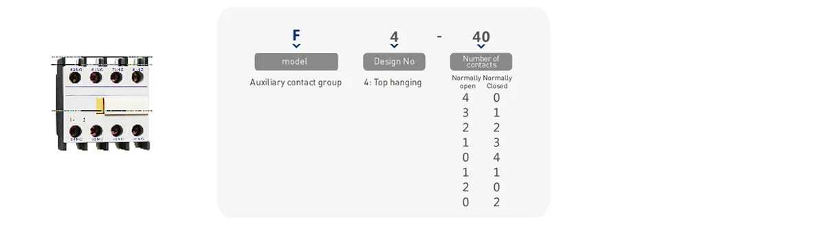
Auxiliary contact specification
| model | Number of contacts | Hook mode | |
| Normally open [NO] | Normally Closed [NC] | ||
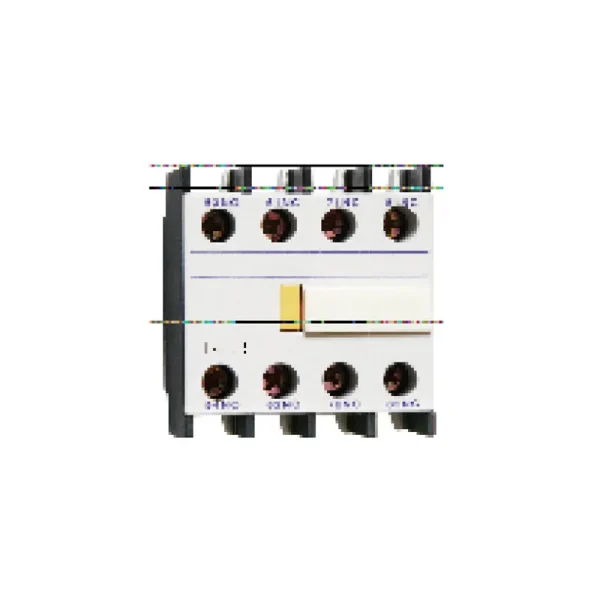
| F4-40 | 4 | 0 | C0C1-09~95 series contactors are top mounted CQC1-115-800 series contactors are side mounted |
| F4-31 | 3 | 1 | |
| F4-22 | 2 | 2 | |
| F4-13 | 1 | 3 | |
| F4-04 | 0 | 4 | |
| F4-20 | 2 | 0 | |
| F4-11 | 1 | 1 | |
| F4-02 | 0 | 2 | |
Technical parameters
09~95A performance index
| CQC1-09 | COC1-12 | COC1-18 | COC1-25 | COC1-32 | COC1-40 | COC1-50 | COC1-65 | CQC1-80 | CQC1-95 | |||
| Rated working current le,A(AC-3) | 400V | 9 | 12 | 18 | 25 | 32 | 40 | 50 | 65 | 80 | 95 | |
| 690V | 6.6 | 8.9 | 12 | 18 | 21 | 34 | 39 | 42 | 49 | 49 | ||
| Agreed free air heating current lth (A) | 25 | 25 | 25 | 40 | 40 | 65 | 80 | 80 | 125 | 125 | ||
| Rated working voltage Ue (V) | 380/400、660/690 | |||||||||||
| Rated insulation voltage Ui (V) | 690V | |||||||||||
| AC-3(6le、le) | Electrical life (times) | 200×104 | 200×104 | 200×104 | 200×104 | 200×104 | 200×104 | 200×104 | 200×104 | 200×104 | 200×104 | |
| Frequent operation(h) | 1200 | 1200 | 1200 | 1200 | 600 | 600 | 600 | 600 | 600 | 600 | ||
| AC-4(6le、6le ) | Electrical life (times) | 20×10 | ||||||||||
| Frequent operation(h) | 300 | |||||||||||
| Rated working current le(A) | 380/400V | 3.5 | 5 | 7.7 | 8.5 | 12 | 18.5 | 24 | 28 | 37 | 44 | |
| 660/690V | 1.5 | 2 | 3.8 | 4.4 | 7.5 | 9 | 12 | 14 | 17.3 | 21.3 | ||
| Mechanical life (times) | 1000×104 | 800×104 | 600×104 | |||||||||
| Contacto auxiliar | Agreed free air heating current lth(A) | 10 | ||||||||||
| Electrical life (times) | AC-15(360VA) | 100×104 | 80×104 | 60×1043 | ||||||||
| DC-13(33W) | ||||||||||||
| Minimum load that can be connected | 24V 10mA | |||||||||||
| Bobina | Rated control supply voltage Us (V) | AC(50Hz/60Hz)24、36、110、220、380;DC:24、48、110、220 | ||||||||||
| pull-in voltage | 85%~110%Us | |||||||||||
| Release voltage | 20%~75% US(AC)10%~75% Us(DC) | |||||||||||
| 50Hz AC coil power (VA) | start | 65 | 65 | 65 | 100 | 100 | 200 | 200 | 200 | 200 | 200 | |
| Sorption | 8 | 8 | 8 | 11 | 11 | 20 | 20 | 20 | 20 | 20 | ||
| DC coil power (w) | start | 11 | 11 | 11 | 13 | 13 | 22 | 22 | 22 | 22 | 22 | |
| Sorption | ||||||||||||
| Wiring capacity of termina mm²(min/max) | Non prefabricated end cord | 1 piece | 1/4 | 1.5/6 | 1.5/10 | 2.5/10 | 2.5/25 | 4/50 | ||||
| 2 pieces | 1/4 | 1.5/6 | 1.5/6 | 2.5/10 | 2.5/16 | 4/25 | ||||||
| Flexible wire with prefabricated end | 1 piece | 1/4 | 1/6 | 1/6 | 1/9 | 2.5/25 | 4/50 | |||||
| 2 pieces | 1/2.5 | 1/4 | 1/4 | 1.5/6 | 2.5/10 | 4/16 | ||||||
| Non prefabricated end hard wire | 1 piece | 1/4 | 1.5/6 | 1.5/6 | 1.5/10 | 2.5/25 | 4/50 | |||||
| 2 pieces | 1/4 | 1.5/6 | 1.5/6 | 1.5/10 | 2.5/16 | 4/25 | ||||||
| Tightening torque of main circuit wiring | N·M | 1.7 | 2.5 | 5 | 9 | |||||||
115A-800A performance index
| technical parameter | CQC1-115 | CQC1-150 | CQC1-185 | CQC1-225 | CQC1-265 | CQC1-330 | CQC1-400 | CQC1-500 | CQC1-630 | CQC1-800 | ||
| Rated working current le(A) | AC-3 | 400V | 115 | 150 | 185 | 225 | 265 | 330 | 400 | 500 | 630 | 800 |
| 690V | 86 | 107 | 118 | 135 | 172 | 225 | 305 | 355 | 460 | 485 | ||
| AC-4 | 400V | 52 | 60 | 79 | 85 | 105 | 117 | 138 | 147 | 188 | 242 | |
| 690V | 49 | 57 | 69 | 82 | 98 | 107 | 135 | 145 | 170 | 215 | ||
| Maximum rated power of controllable three-phase squirrel cage motor Pe (k) | AC-3 | 400V | 55 | 75 | 90 | 110 | 132 | 160 | 200 | 250 | 335 | 450 |
| 690V | 80 | 100 | 110 | 129 | 160 | 220 | 280 | 335 | 450 | 475 | ||
| AC-4 | 400V | 25 | 30 | 40 | 45 | 55 | 63 | 75 | 80 | 100 | 129 | |
| 690V | 45 | 51 | 63 | 75 | 90 | 100 | 129 | 140 | 160 | 200 | ||
| Agreed free air heating current lth (A) | 200 | 200 | 280 | 280 | 360 | 360 | 580 | 580 | 850 | 850 | ||
| Rated working voltage Ue (V) | 400、690 | |||||||||||
| Rated insulation voltage Ui (V) | 690 | |||||||||||
| AC-3 | Electrical life (times) | 60×104 | 50×104 | 30×104 | 20×104 | 15×104 | ||||||
| Frequent operation (h) | 600 | 300 | 150 | |||||||||
| AC-4 | Electrical life (times) | 15×104 | 8×10⁴ | 5×10⁴ | 3×10⁴ | |||||||
| Frequent operation (h) | 150 | |||||||||||
| Mechanical life (times) | 300×104 | 100×104 | 60×104 | |||||||||
| Contacto auxiliar | Agreed free air heating current lth (A) | 10 | ||||||||||
| Electrical life (times) | AC-15(360VA) | 60×104 | 50×104 | 30×104 | 15×104 | |||||||
| DC-13(33W) | ||||||||||||
| Coil parameters | Rated control supply voltage Us (V) | AC50HZ:24、48 110 230(220)240 (double coil energy-saving type(380) | AC50HZ:48、110 230(220)240 (double coil energy-saving type(380) | |||||||||
| pull-in voltage | 85%~110%Us | |||||||||||
| Release voltage | 20%~75%Us | |||||||||||
| coil power (VA) | start | 560 | 800 | 750 | 1000 | 1100 | 1600 | |||||
| Sorption | 45 | 55 | 8 | 12 | 16 | 20 | ||||||
| Pickup time (ms) | 23~35 | 20~35 | 30~65 | 40~75 | 40~80 | 50~100 | ||||||
| Release time (ms) | 5~15 | 7~15 | 100~170 | 100~170 | 100~200 | 130~230 | ||||||
| Main circuit connection capacity | Copper conductor | Number of roots | 1 | 1 | 1 | 1 | 1 | 1 | 2 | 2 | – | |
| Conductor section mm | 120 | 150 | 185 | 240 | 240 | 150 | 240 | – | ||||
| Copper bar | Number of roots | 2 | 2 | 2 | 2 | 2 | 2 | 2 | 2 | 2 | 2 | |
| Dimension mm | 20×3 | 25×3 | 25×3 | 32×4 | 32×4 | 30×5 | 30×5 | 50×5 | 60×5 | 60×5 | ||
| Auxiliary circuit contrd circuit | Flexible cord mm² |
1 | 2.5 | |||||||||
| 2 | ||||||||||||
| Hard wire mm² | 1 | 4 | ||||||||||
| 2 | ||||||||||||
¿Por qué elegir CHAC?
Con más de 30 años de experiencia en fabricación, más de 1100 empleados, más de 100 millones de postes
Con una capacidad anual y un proceso de producción automatizado 90%, CHAC ofrece una capacidad de producción estable y un estricto
control de calidad para clientes OEM/ODM globales. Nuestro sistema de fabricación interno respalda a largo plazo
Cooperación para marcas eléctricas, importadores y distribuidores.

30+
AÑOS DE EXPERIENCIA
Especializado en fabricación eléctrica de bajo voltaje

1100+
EMPLEADOS
Equipo profesional garantiza calidad y entrega estables

100M+
CAPACIDAD ANUAL DE LOS POLOS
Capacidad de producción a gran escala para satisfacer la demanda mundial

90%
PRODUCCIÓN AUTOMATIZADA
Automatización avanzada para alta eficiencia y consistencia
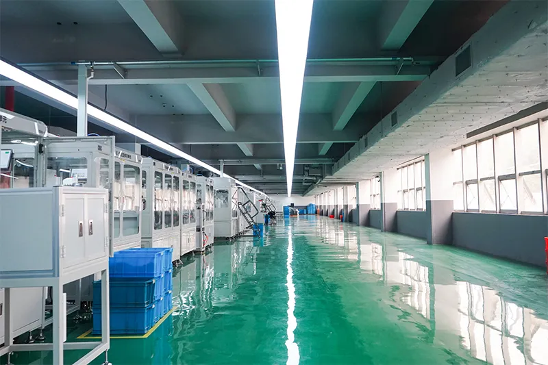
Línea de ensamblaje automatizada

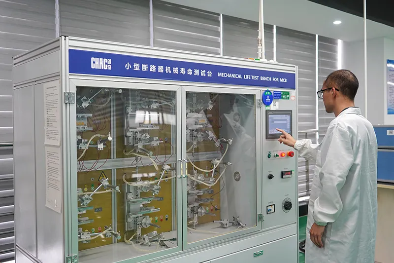
Laboratorio de pruebas
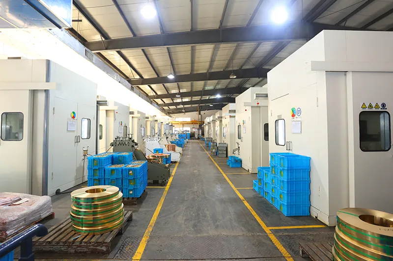
Inyección y Estampado
Inspección de calidad



Un estricto sistema de control de calidad garantiza que cada producto cumpla con los estándares mundiales.
¿Qué podemos personalizar?
CHAC admite la personalización del voltaje de la bobina y la configuración de los contactos auxiliares.,
parámetros eléctricos, marca del producto, diseño de envasado y desarrollo de ingeniería según los equipos y requisitos de mercado de los clientes.

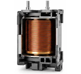
Voltaje de la bobina
Opciones de voltaje de bobina de CA y CC adaptadas a los requisitos de la aplicación.

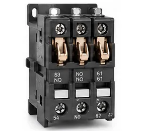
Contactos Auxiliares
Combinaciones flexibles de contactos auxiliares para diferentes funciones de control.

Parámetros eléctricos
Las clasificaciones actuales, los rangos de protección y los parámetros funcionales se pueden personalizar.
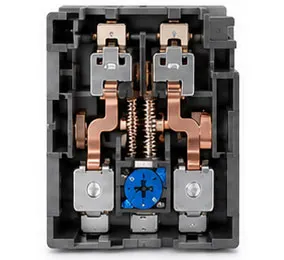

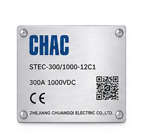
Marca de producto
Logotipos de marca privada, placas de identificación y soporte para la identificación de productos.

Diseño de empaque
Soluciones de embalaje, cajas personalizadas, etiquetas y manuales.

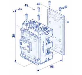
Desarrollo de Ingeniería
Soporte desde la optimización de dibujos hasta el desarrollo de productos y la adaptación de aplicaciones.
CQC1 Product FAQ
What loads can the CQC1 contactor switch?
Use the published utilization category, operational current and voltage for the selected variant. Resistive, motor and capacitive loads require different checks.
How do I select an AC contactor size?
Start with load current, utilization category, starts per hour, coil voltage, poles and short-circuit coordination. Current alone is not enough.
Can a thermal relay be paired with it?
Where the product record supports the combination, a thermal relay can form a motor starter. Confirm mechanical fit, current range and control wiring.
Which coil voltage should I specify?
Match the control supply shown on the project drawing with the coil option for the exact model. Never assume the coil voltage from the main circuit.
What accessories are available?
Auxiliary contacts, timers, interlocks or other accessories depend on the series and variant. Confirm the compatible accessory list before ordering.
How should a contactor be commissioned?
Verify terminal torque, coil voltage, contact sequence, insulation and operating current, then record the test results.
Confirm the Right CQC1 Configuration
Send the exact model, operating conditions, quantity, destination market and required documents. CHAC will review the request against the published product data.