CQC1 Series High-Duty AC Contactor and Accessories
Scope of application and use
COC1-09~800series AC contactors(hereinafter referred to as contactors)are mainly used for AC 50 Hz(60Hz) In the circuit with rated working voltage of 690V and rated working current of9A~800A,it is used for making and breaking the circuit remotely And frequently starting and controlling AC motors; And can form an electromagnetic starter with an thermal overload relay,To protect circuits that may be overloaded.Comply with IEC 60947-4,GB/ T14048.4, IEC60947-5, GB/T14048.5.
Applicable environment
◆Operating temperature
Standard operating temperature:-25℃~+40℃
Limit service temperature:-40℃~+70℃
Storage temperature:-60℃~+80℃
◆Use altitude
Normal use altitude:< 2000m
Limit service altitude:< 5000m
◆Pollution level: pollution level 3
◆Installation category: Class ll
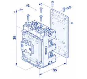
◆Installation method:screw installation.35mm and 75mm can also be used for 09A~95A products.
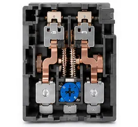
Structural features
◆The action mechanism is direct acting, and the contact is double break point;
◆Strong combination function, and the mounting surface can be equipped with accessories;
◆Reversible mechanism can be installed on both sides to form a reversible contactor; Auxiliary contact group(F4) and air delay head (S4)(09A~95A)can be installed above; Auxiliary contact group(F4) and air delay head (S4)(115A~800A)can be installed on the right side;
◆Protective type Protection grade IP20;
◆The contactor shall comply with the provisions of use categoryAC-3,operation level 0.l and load 60% value or equivalent national standard;
◆The contactor can be equipped with thermal overload relay,mechanical interlocking module,auxiliary contact,etc .To expand product functions.
Model and Meaning

Note 1: 09A~95A is in the form of auxiliary contact, and 115A~800Aisconventional without auxiliary10 indicates three normally open main contacts and one normally open auxiliary contact (32A and below)01 represents three normally open main contacts and one normally closed auxiliary contact (32A and below)11 represents three normally open main contacts, one normally open and one normally closed auxiliary contact (40~95A).
Appearance and installation dimensions
CQC1-09 12、18、25、32
| Contactor model | Amax | Bmax | Cmax | a | C1 | C2 |
| CQC1-09、12 | 47 | 76 | 82 | 35±0.50 | 113 | 133 |
| CQC1-18 | 87 | 118 | 138 | |||
| CQC1-25 | 57 | 86 | 95 | 40±0.50 | 126 | 146 |
| CQC1-32 | 100 | 131 | 151 |
Note: C1:CQC1+F4 C2:CQC1+S4
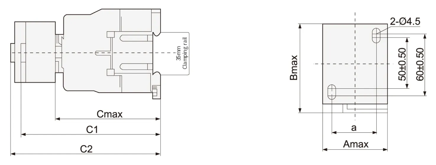
CQC1-40、50、65、80、95
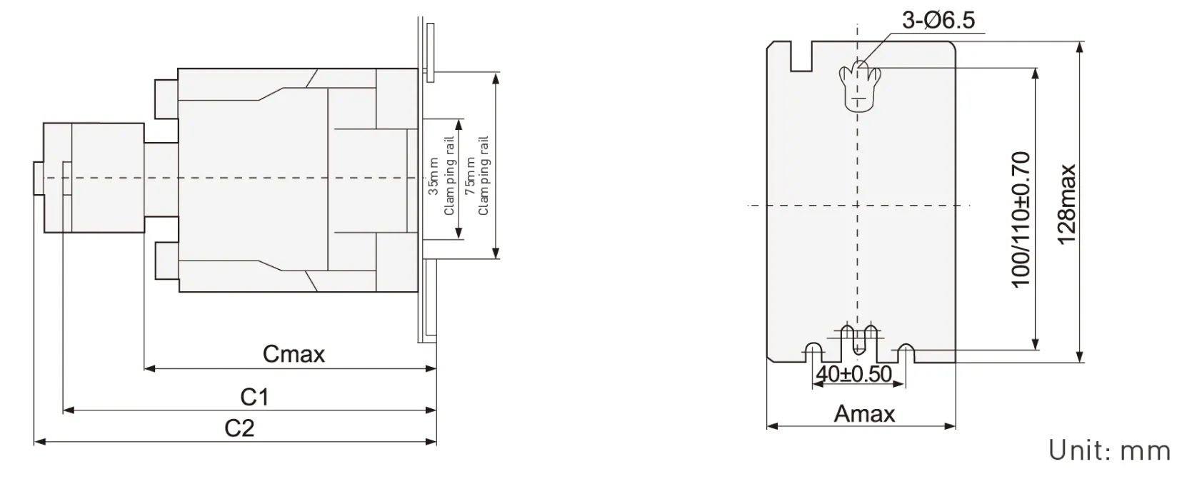
| Contactor model | Amax | Cmax | C1 | C2 |
| CQC1-4011-6511 | 77 | 116 | 145 | 165 |
| CQC1-8011~9511 | 87 | 127 | 175 | 195 |
Note:C1:CQC1+F4 C2:CQC1+S4
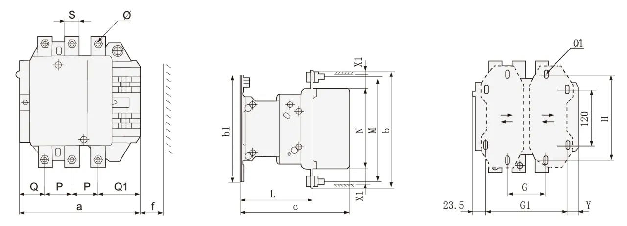
C0C1-115~330 overall dimensions and installation dimensions [tolerance: ± 1mm]

| CQC1 | a | P | Q | Q1 | S | Φ | f | b | b1 | M | N | c | L | G | H | Φ1 | G1 | Z | Y | X1 | |
| ≤500V | >500V | ||||||||||||||||||||
| 115 | 163.5 | 37 | 29.5 | 60 | 20 | M6 | 131 | 162 | 137 | 147 | 124 | 171 | 107 | 80 | 120-106 | 6.5 | 106 | 13.5 | 44 | 10 | 15 |
| 150 | 163.5 | 40 | 26 | 57.5 | 20 | M8 | 131 | 170 | 137 | 150 | 124 | 171 | 107 | 80 | 120-106 | 6.5 | 106 | 13.5 | 44 | 10 | 15 |
| 185 | 168.5 | 40 | 29 | 59.5 | 20 | M8 | 130 | 174 | 137 | 154 | 127 | 181 | 113.5 | 80 | 120-106 | 6.5 | 111 | 13.5 | 44 | 10 | 15 |
| 225 | 168.5 | 48 | 21 | 51.5 | 25 | M10 | 130 | 197 | 137 | 172 | 127 | 181 | 113.5 | 80 | 120-106 | 6.5 | 111 | 13.5 | 44 | 10 | 15 |
| 265 | 205 | 48 | 39 | 66.5 | 25 | M10 | 147 | 203 | 145 | 180 | 147 | 213 | 141 | 96 | 120-106 | 6.5 | 140 | 20.5 | 38 | 10 | 15 |
| 330 | 213 | 48 | 43 | 74 | 25 | M10 | 147 | 209 | 145 | 184 | 158 | 219 | 145 | 96 | 120-106 | 6.5 | 154.5 | 20.5 | 38 | 10 | 15 |
Note: f is the space required for coil replacement
X1 is the minimum electrical clearance [Flying Fox distance)the same as below
CQC1-400-500 overall dimensions and installation dimensions(tolerance: ± 1mm)
| CQC1 | a | P | Q | Q1 | S | Φ | f | b | b1 | M | N | c | L | G | G1 | Φ1 | H | Y | X1 | |
| ≤500V | >500V | |||||||||||||||||||
| 400 | 213 | 48 | 43 | 74 | 25 | M10 | 151 | 206 | 209 | 181 | 158 | 219 | 145 | 80(66-102) | 170(156-192) | 8.5 | 180 | 19.5 | 15 | 20 |
| 500 | 233 | 46 | 46 | 77 | 30 | M10 | 169 | 238 | 209 | 208 | 172 | 232 | 146 | 80(66-102) | 170(156-210) | 8.5 | 180 | 39.5 | 15 | 20 |
CQC1-630-800 overall dimensions and installation dimensions(tolerance: ± 1mm)
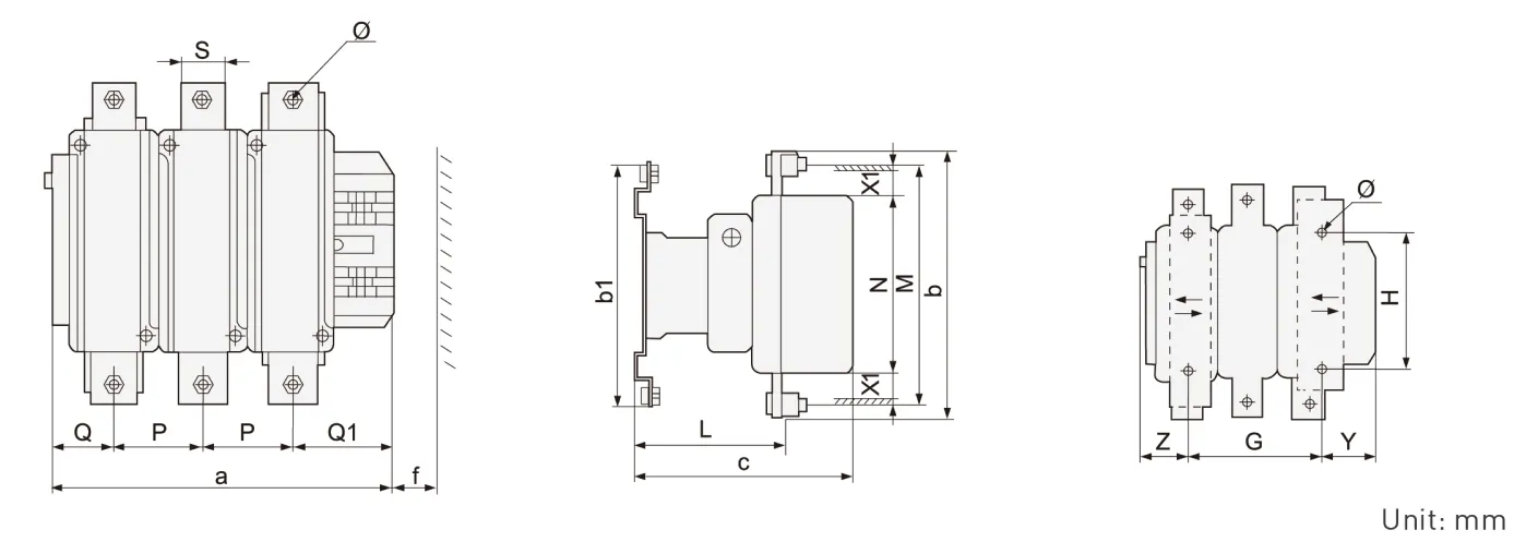
| CQC1 | a | P | Q | Q1 | S | Φ | f | b | b1 | M | N | c | L | G | H | Φ1 | Z | Y | X1 | |
| ≤500V | >500V | |||||||||||||||||||
| 630/800 | 309 | 80 | 60 | 89 | 40 | M12 | 201 | 304 | 280 | 264 | 202 | 255 | 155 | 180(100-195) | 180 | 10.5 | 60.5 | 68.5 | 20 | 30 |
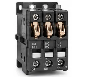
CQC1 Series Accessories
Quick selection table/specification

Specification of auxiliary contact [air delay type]
| model | Delay range | Number of delayed contacts | Delay mode | Hook mode |
| S4-20 | 0.1s~3s | 1NO+1NC | Power on delay | Top hanging |
| S4-22 | 0.1s~30s | |||
| S4-24 | 10s~180s | |||
| S5-20 | 0.1s~3s | Power off delay | ||
| S5-22 | 0.1s~30s | |||
| S5-24 | 10s~180s |
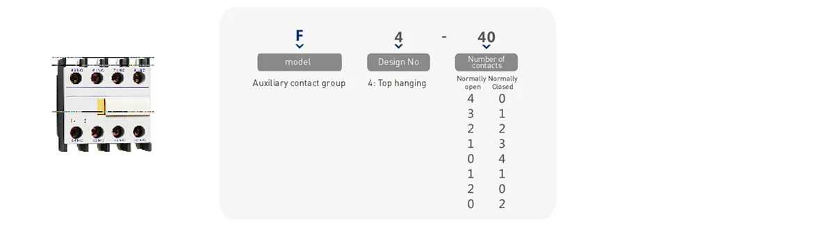
Auxiliary contact specification
| model | Number of contacts | Hook mode | |
| Normally open [NO] | Normally Closed [NC] | ||
| F4-40 | 4 | 0 | C0C1-09~95 series contactors are top mounted CQC1-115-800 series contactors are side mounted |
| F4-31 | 3 | 1 | |
| F4-22 | 2 | 2 | |
| F4-13 | 1 | 3 | |
| F4-04 | 0 | 4 | |
| F4-20 | 2 | 0 | |
| F4-11 | 1 | 1 | |
| F4-02 | 0 | 2 | |
Technical parameters
09~95A performance index
| CQC1-09 | COC1-12 | COC1-18 | COC1-25 | COC1-32 | COC1-40 | COC1-50 | COC1-65 | CQC1-80 | CQC1-95 | |||
| Rated working current le,A(AC-3) | 400V | 9 | 12 | 18 | 25 | 32 | 40 | 50 | 65 | 80 | 95 | |
| 690V | 6.6 | 8.9 | 12 | 18 | 21 | 34 | 39 | 42 | 49 | 49 | ||
| Agreed free air heating current lth (A) | 25 | 25 | 25 | 40 | 40 | 65 | 80 | 80 | 125 | 125 | ||
| Rated working voltage Ue (V) | 380/400、660/690 | |||||||||||
| Rated insulation voltage Ui (V) | 690V | |||||||||||
| AC-3(6le、le) | Electrical life (times) | 200×104 | 200×104 | 200×104 | 200×104 | 200×104 | 200×104 | 200×104 | 200×104 | 200×104 | 200×104 | |
| Frequent operation(h) | 1200 | 1200 | 1200 | 1200 | 600 | 600 | 600 | 600 | 600 | 600 | ||
| AC-4(6le、6le ) | Electrical life (times) | 20×10 | ||||||||||
| Frequent operation(h) | 300 | |||||||||||
| Rated working current le(A) | 380/400V | 3.5 | 5 | 7.7 | 8.5 | 12 | 18.5 | 24 | 28 | 37 | 44 | |
| 660/690V | 1.5 | 2 | 3.8 | 4.4 | 7.5 | 9 | 12 | 14 | 17.3 | 21.3 | ||
| Mechanical life (times) | 1000×104 | 800×104 | 600×104 | |||||||||
| Auxiliary contact | Agreed free air heating current lth(A) | 10 | ||||||||||
| Electrical life (times) | AC-15(360VA) | 100×104 | 80×104 | 60×1043 | ||||||||
| DC-13(33W) | ||||||||||||
| Minimum load that can be connected | 24V 10mA | |||||||||||
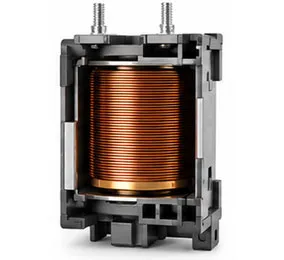
| Coil | Rated control supply voltage Us (V) | AC(50Hz/60Hz)24、36、110、220、380;DC:24、48、110、220 | ||||||||||
| pull-in voltage | 85%~110%Us | |||||||||||
| Release voltage | 20%~75% US(AC)10%~75% Us(DC) | |||||||||||
| 50Hz AC coil power (VA) | start | 65 | 65 | 65 | 100 | 100 | 200 | 200 | 200 | 200 | 200 | |
| Sorption | 8 | 8 | 8 | 11 | 11 | 20 | 20 | 20 | 20 | 20 | ||
| DC coil power (w) | start | 11 | 11 | 11 | 13 | 13 | 22 | 22 | 22 | 22 | 22 | |
| Sorption | ||||||||||||
| Wiring capacity of termina mm²(min/max) | Non prefabricated end cord | 1 piece | 1/4 | 1.5/6 | 1.5/10 | 2.5/10 | 2.5/25 | 4/50 | ||||
| 2 pieces | 1/4 | 1.5/6 | 1.5/6 | 2.5/10 | 2.5/16 | 4/25 | ||||||
| Flexible wire with prefabricated end | 1 piece | 1/4 | 1/6 | 1/6 | 1/9 | 2.5/25 | 4/50 | |||||
| 2 pieces | 1/2.5 | 1/4 | 1/4 | 1.5/6 | 2.5/10 | 4/16 | ||||||
| Non prefabricated end hard wire | 1 piece | 1/4 | 1.5/6 | 1.5/6 | 1.5/10 | 2.5/25 | 4/50 | |||||
| 2 pieces | 1/4 | 1.5/6 | 1.5/6 | 1.5/10 | 2.5/16 | 4/25 | ||||||
| Tightening torque of main circuit wiring | N·M | 1.7 | 2.5 | 5 | 9 | |||||||
115A-800A performance index
| technical parameter | CQC1-115 | CQC1-150 | CQC1-185 | CQC1-225 | CQC1-265 | CQC1-330 | CQC1-400 | CQC1-500 | CQC1-630 | CQC1-800 | ||
| Rated working current le(A) | AC-3 | 400V | 115 | 150 | 185 | 225 | 265 | 330 | 400 | 500 | 630 | 800 |
| 690V | 86 | 107 | 118 | 135 | 172 | 225 | 305 | 355 | 460 | 485 | ||
| AC-4 | 400V | 52 | 60 | 79 | 85 | 105 | 117 | 138 | 147 | 188 | 242 | |
| 690V | 49 | 57 | 69 | 82 | 98 | 107 | 135 | 145 | 170 | 215 | ||
| Maximum rated power of controllable three-phase squirrel cage motor Pe (k) | AC-3 | 400V | 55 | 75 | 90 | 110 | 132 | 160 | 200 | 250 | 335 | 450 |
| 690V | 80 | 100 | 110 | 129 | 160 | 220 | 280 | 335 | 450 | 475 | ||
| AC-4 | 400V | 25 | 30 | 40 | 45 | 55 | 63 | 75 | 80 | 100 | 129 | |
| 690V | 45 | 51 | 63 | 75 | 90 | 100 | 129 | 140 | 160 | 200 | ||
| Agreed free air heating current lth (A) | 200 | 200 | 280 | 280 | 360 | 360 | 580 | 580 | 850 | 850 | ||
| Rated working voltage Ue (V) | 400、690 | |||||||||||
| Rated insulation voltage Ui (V) | 690 | |||||||||||
| AC-3 | Electrical life (times) | 60×104 | 50×104 | 30×104 | 20×104 | 15×104 | ||||||
| Frequent operation (h) | 600 | 300 | 150 | |||||||||
| AC-4 | Electrical life (times) | 15×104 | 8×10⁴ | 5×10⁴ | 3×10⁴ | |||||||
| Frequent operation (h) | 150 | |||||||||||
| Mechanical life (times) | 300×104 | 100×104 | 60×104 | |||||||||
| Auxiliary contact | Agreed free air heating current lth (A) | 10 | ||||||||||
| Electrical life (times) | AC-15(360VA) | 60×104 | 50×104 | 30×104 | 15×104 | |||||||
| DC-13(33W) | ||||||||||||
| Coil parameters | Rated control supply voltage Us (V) | AC50HZ:24、48 110 230(220)240 (double coil energy-saving type(380) | AC50HZ:48、110 230(220)240 (double coil energy-saving type(380) | |||||||||
| pull-in voltage | 85%~110%Us | |||||||||||
| Release voltage | 20%~75%Us | |||||||||||
| coil power (VA) | start | 560 | 800 | 750 | 1000 | 1100 | 1600 | |||||
| Sorption | 45 | 55 | 8 | 12 | 16 | 20 | ||||||
| Pickup time (ms) | 23~35 | 20~35 | 30~65 | 40~75 | 40~80 | 50~100 | ||||||
| Release time (ms) | 5~15 | 7~15 | 100~170 | 100~170 | 100~200 | 130~230 | ||||||
| Main circuit connection capacity | Copper conductor | Number of roots | 1 | 1 | 1 | 1 | 1 | 1 | 2 | 2 | – | |
| Conductor section mm | 120 | 150 | 185 | 240 | 240 | 150 | 240 | – | ||||
| Copper bar | Number of roots | 2 | 2 | 2 | 2 | 2 | 2 | 2 | 2 | 2 | 2 | |
| Dimension mm | 20×3 | 25×3 | 25×3 | 32×4 | 32×4 | 30×5 | 30×5 | 50×5 | 60×5 | 60×5 | ||
| Auxiliary circuit contrd circuit | Flexible cord mm² |
1 | 2.5 | |||||||||
| 2 | ||||||||||||
| Hard wire mm² | 1 | 4 | ||||||||||
| 2 | ||||||||||||
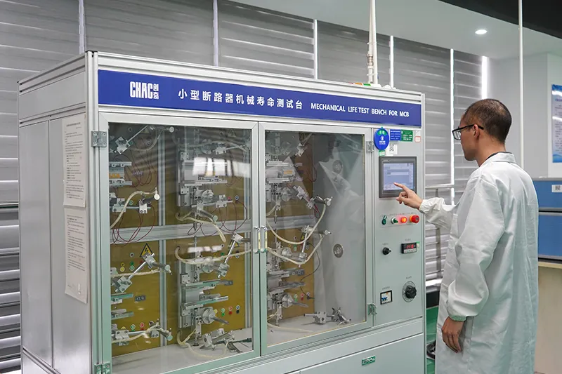
Why Choose CHAC
With 30+ years of manufacturing experience, 1100+ employees, 100M+ poles
annual capacity and 90% automated production, CHAC provides stable production capacity and strict
quality control for global OEM/ODM customers. Our in-house manufacturing system supports long-term
cooperation for electrical brands, importers and distributors.
30+
YEARS EXPERIENCE
Specialized in low-voltage electrical manufacturing
1100+
EMPLOYEES
Professional team ensures stable quality and delivery
100M+
POLES ANNUAL CAPACITY
Large-scale production capacity to meet global demand
90%
AUTOMATED PRODUCTION
Advanced automation for high efficiency and consistency
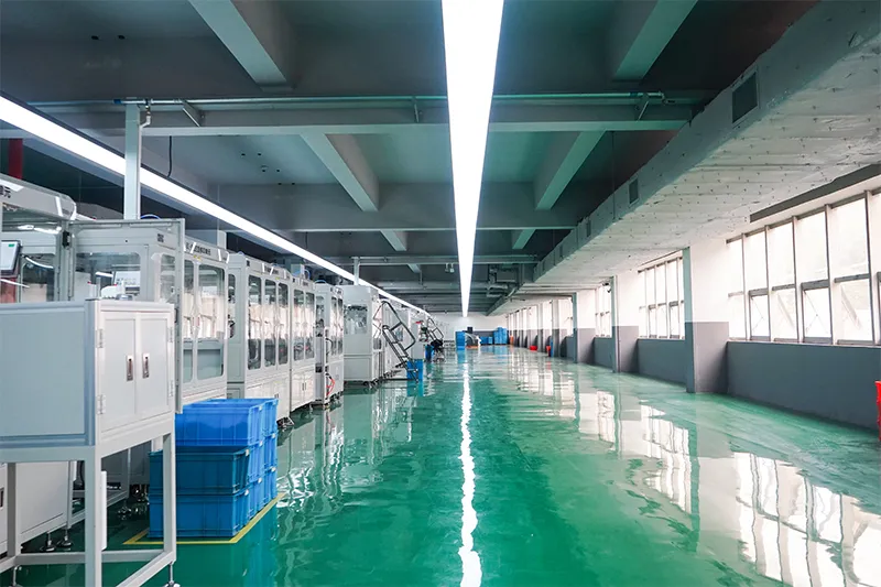
Automated Assembly Line

Testing Laboratory
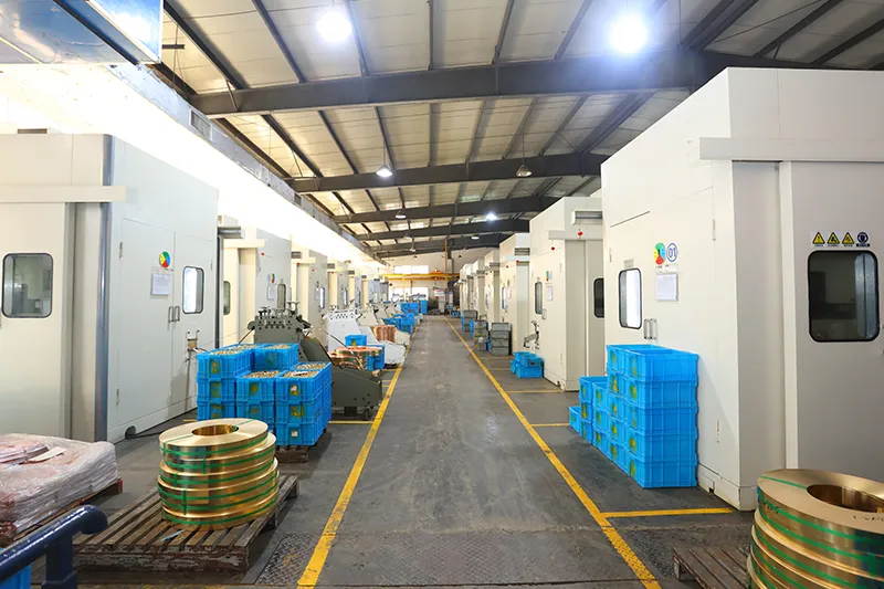
Injection & Stamping
Quality Inspection


Strict quality control system ensures every product meets global standards.
What Can We Customize?
CHAC supports customization of coil voltage, auxiliary contact configuration,
electrical parameters, product branding,packaging design and engineering development according to customers’ equipment and market requirements.
Coil Voltage
AC and DC coil voltage options tailored to application requirements.
Auxiliary Contacts
Flexible auxiliary contact combinations for different control functions.
Electrical Parameters
Current ratings, protection ranges and functional parameters can be customized.
Product Branding
Private label logos, nameplates and product identification support.
Packaging Design
Custom cartons, labels, manuals and packaging solutions.
Engineering Development
Support from drawing optimization to product development and application matching.