Considere un proyecto hipotético de cuadro eléctrico en Bangkok. El equipo de compras solicita un interruptor 1600 antes de que se haya definido la disposición de las conexiones. Durante la fabricación, el constructor del panel descubre que los terminales y las curvas de cable propuestos requieren más espacio del que ofrece la configuración de la caja. La corriente nominal del interruptor era solo una parte de la especificación. La disposición de los terminales y el espacio circundante deberían haberse acordado antes de que se iniciara la fabricación de la estructura metálica.
Resumen: Un MCCB 1600A puede considerarse dentro de disposiciones de cable o barra colectora únicamente cuando el interruptor exacto, el hardware de los terminales y el diseño del ensamblaje lo permiten. CQM6-1600 está catalogado como un marco 3-pole. Ni la designación 1600 ni una fotografía de la serie establecen el terminal aprobado, el tamaño de la barra colectora, el par de apriete ni la cantidad de cables por terminal.
¿Qué dibujos de terminales de CQM6 se necesitan antes de elegir una conexión 1600 A?
Una solicitud de compra para un/a 1600 interruptor automático de circuito debe identificar tanto el marco como la corriente nominal requerida. La información técnica de CQM6 enumera varias opciones de corriente dentro del marco CQM6-1600. Por lo tanto, la designación del marco por sí sola no define completamente el dispositivo de protección suministrado, y mucho menos los conductores conectados a él.
Obtenga el esquema y el plano de instalación específicos del modelo, el detalle de los terminales, los accesorios de conexión aprobados y las instrucciones de instalación. Confirme su versión y los sufijos de pedido a los que corresponden. Una vista frontal puede mostrar la forma general del producto, pero no permite determinar una disposición de conexiones oculta, la configuración de apilamiento de elementos de fijación ni el espacio libre trasero.
El listado público de CQM6 proporciona las dimensiones del marco y la información general de pedido. Estos datos son útiles para la planificación preliminar. No deben utilizarse para inferir una disposición permitida de las terminales de cable ni el par de apriete cuando no se disponga de instrucciones específicas. Registre los detalles de conexión pendientes en la consulta técnica y resuélvalos antes de la fabricación.
Las ilustraciones del producto en este artículo utilizan un ejemplo de apariencia de la serie CQM6. No son dibujos dimensionales ni demostraciones de una instalación aprobada de cable o barra colectora CQM6-1600. Para la producción, rigen los documentos aprobados del modelo seleccionado.
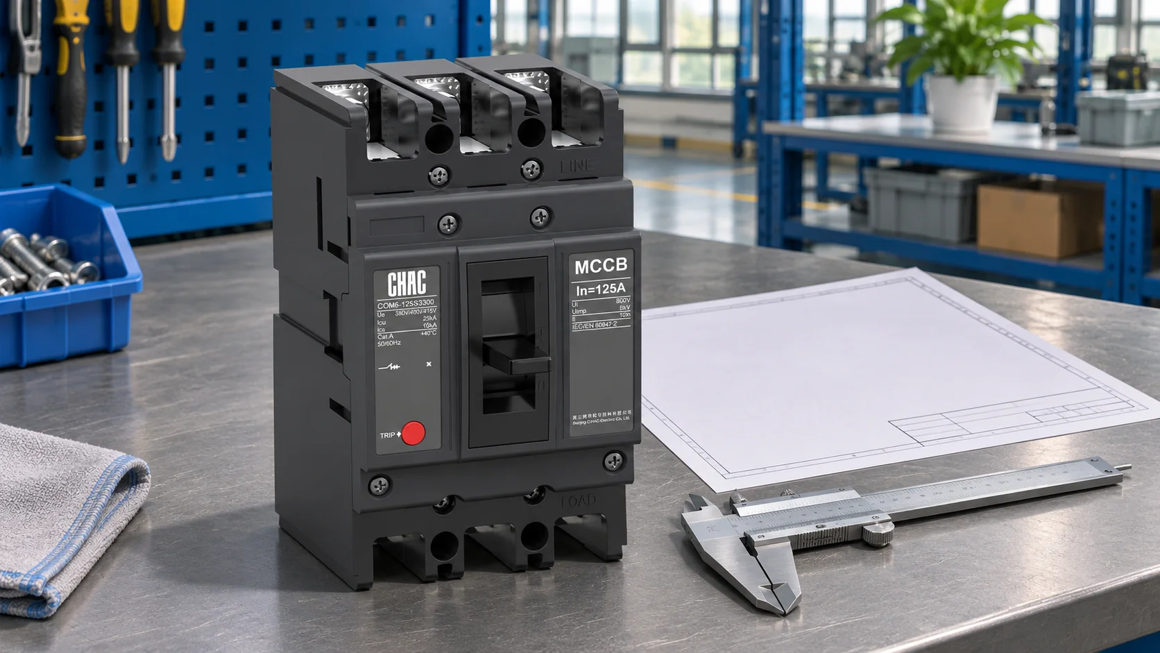
Compare las conexiones de terminales de cable y de barra colectora para el diseño completo del panel.
Borne de interruptor automático Debe ser adecuado para el terminal, el material del conductor, la construcción del conductor y la sección transversal. El hecho de que un orificio encaje sobre un perno no es suficiente. Las dimensiones de las abrazaderas, su orientación, el aislamiento, los elementos de fijación y la cantidad de conductores permitidos en un terminal deben estar en conformidad con la disposición aprobada.
A conexión de barra colectora también requiere más que una estimación de la densidad de corriente. Su material conductor, las dimensiones, el diseño de las uniones, los soportes, la elevación de temperatura y el rendimiento en caso de cortocircuito forman parte de la evaluación completa del conjunto. Un interruptor 1600 no establece una sección transversal universal para las barras de cobre. Tampoco establece que un adaptador propuesto sea adecuado para el terminal del interruptor.
| Punto de revisión | Propuesta basada en cable | Propuesta basada en barras colectoras |
|---|---|---|
| Interfaz de terminal | Tuerca o conector aprobado y número permitido de conductores | Interfaz de contacto, adaptador y disposición de sujeción aprobados |
| Espacio | Orientación de los conectores, radio de curvatura del cable y trazado | Geometría del cuadro, soportes y acceso a las uniones |
| Evaluación térmica | Condiciones de instalación, agrupación y terminación de conductores | Aumento de la temperatura en la barra y en la junta dentro del recinto real |
| Evaluación mecánica | Soporte de cable sin carga terminal inadecuada | Soporte y evaluación de la fuerza de falla del sistema |
| Servicio | Acceso para inspeccionar y rehacer las terminaciones aprobadas | Access to inspect joints and the relevant supports |
There is no general rule that cables are always easier or busbars always cheaper. A cable proposal can require substantial bending space and termination work. A busbar proposal can require custom fabrication and careful control of joint geometry. Compare the complete design, manufacturing work and maintenance access for the actual panel.
Check cable bends, phase clearances and access around the 1600 A connection
The outline of the breaker is only the starting envelope. Add the selected connection hardware, conductor approach, cable bends or bar route, phase separation, barriers and tool access. Confirm clearances from the applicable instructions and assembly design. Do not obtain a critical distance by measuring a catalogue photograph.
IEC 61439-1:2020 covers construction, technical characteristics and verification requirements for low-voltage assemblies, used with the relevant assembly part. It explicitly addresses temperature-rise verification and group rated current. This supports a practical distinction: a component’s 1600 A marking does not prove that every enclosure and conductor arrangement can carry 1600 A under its service conditions.
If parallel cables are proposed, document the conductor characteristics and arrangement required by the applicable design and installation rules. Multiple cables may affect space, grouping and current sharing. They are not an automatic substitute for a terminal-approved single-conductor or busbar arrangement. The terminal’s permitted number of conductors must be confirmed independently.
| Document or decision | Information to capture | When it is needed |
|---|---|---|
| One-line diagram | Supply, circuit duty, protection and fault level | Before device selection |
| Terminal detail | Connection option and approved interface hardware | Before ordering lugs or adapters |
| Enclosure layout | Device, connection route, clearances and servicing access | Before metalwork release |
| Assembly verification | Applicable thermal and short-circuit assessment | Before accepting the finished design |
| Installation instructions | Conductor preparation, fastening procedure and torque | Before assembly and inspection |
A useful drawing-review habit is to show the complete connection envelope on the same drawing revision as the enclosure. This lets the breaker supplier, panel builder and installer discuss the same arrangement. Otherwise, each party can approve a different piece while the assembled result still fails to fit.
IEC TR 61439-0:2022 provides guidance on the functions and characteristics a specifier should define for an assembly. It supports agreeing application and interface requirements before manufacture. Treat it as specification guidance, alongside the applicable assembly requirements, rather than as approval of a particular cable lug or busbar joint.
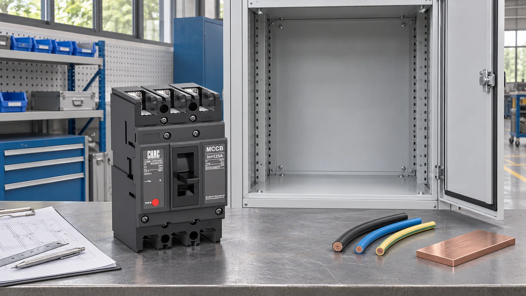
Confirm which CQM6 connection hardware is included in the order
CHAC CQM6 standard MCCB information identifies a range up to 1600 A and lists CQM6-1600 as 3P. Use that page to identify the family, then request confirmation for the exact proposed connection. Do not extend an accessory option from a smaller frame to CQM6-1600 without supporting data.
Ask the supplier to identify what is supplied with the breaker and what must be ordered separately. Depending on the approved arrangement, the review may include terminal hardware, adapters, covers, phase barriers and operating accessories. List the required items rather than assuming every part visible in a series brochure is included.
El MCCB procurement guide provides the broader order-review context. For this connection decision, send the conductor proposal, enclosure drawing and required quantity with the enquiry. Ask who approves the final interface and who is responsible for the assembly design.
IEC 60947-2:2024 addresses the circuit-breaker product; IEC 61439 addresses the assembly. Referencing either standard does not establish that a particular CQM6 order or connection has every approval required in the destination market. Verify the exact model records and the applicable installation rules. The MCCB category can help locate alternatives when the proposed frame or interface cannot meet the layout.
Finally, compare the installed cost. Include approved lugs or bar fabrication, enclosure space, labour, verification and future access. A cheaper connection kit that requires a cabinet redesign may be the more expensive option. No cost estimate should assume an unapproved connection will be accepted later.
Common questions about CQM6 1600 A cable and busbar connections
Can a 1600A MCCB use cable lugs as well as busbar connections?
It depends on the exact model and approved connection options. Some arrangements may be available through specific terminal hardware or adapters, but the current rating alone does not establish compatibility. Obtain confirmation for the selected CQM6 frame and proposed conductors.
Which terminal drawings are needed before choosing a CQM6 connection arrangement?
Request the exact model’s terminal detail, outline and mounting drawing, accessory drawing and installation instructions. Confirm the revision and ordering code covered. Include the surrounding enclosure layout in the review.
How should conductor material and the number of cables per terminal be specified?
State the conductor material, construction, cross-section and intended number per terminal. Include the lug or connector proposal and cable arrangement. The manufacturer must confirm the terminal’s permitted configuration; physical fit is insufficient.
Does a 1600A breaker rating alone determine the required busbar size?
No. Material, arrangement, enclosure temperature, joint design and short-circuit duties affect the assembly assessment. Use the approved design and relevant verification, rather than a universal bar size taken from the breaker current.
Which lug and terminal hardware should be included in the supply scope?
Identify the approved lugs or adapters, fasteners and any required covers or phase barriers. Ask which items are included and which are separate. Do not prescribe a fastening stack without the manufacturer’s connection instructions.
How should bending space and phase separation be checked around a high-current connection?
Review the full conductor route and connection envelope on the enclosure drawing. Apply the cable manufacturer’s bend requirements, the breaker’s clearances and the assembly design. Include access for installation and inspection.
Where should the approved tightening torque and termination procedure be obtained?
Use the installation instructions for the exact breaker, terminal kit and conductor arrangement. If they are missing, request them before installation. A bolt size, photograph or torque value from another model is not a valid substitute.
Referencias
- IEC 60947-2:2024: circuit-breaker product scope.
- IEC 61439-1:2020: low-voltage assembly construction and verification.
- IEC TR 61439-0:2022: guidance for defining assembly functions and interfaces.
The CQM6 product information linked above supplies the frame and pole data. Specific lug compatibility, busbar dimensions and tightening torque require the selected connection documents.
Agree the connection before the enclosure is built. Send CHAC the CQM6 frame, conductor proposal and panel layout to clarify the model-specific supply scope.