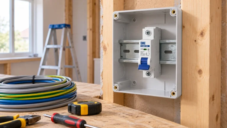
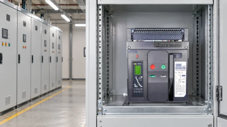
Two breakers can clip onto the same rail and still be unsuitable for the same enclosure. Their terminals may sit at different heights, an accessory can add unexpected width, or a busbar may not align with the connection openings. These problems often appear only after the enclosure and cable ducts have been ordered. The mounting rail answers one mechanical question; it does not settle electrical coordination or assembly approval. This guide explains what the rail designation means, which MCB dimensions control the finished layout and how to check mixed components without assuming that “DIN rail mounted” makes them interchangeable.
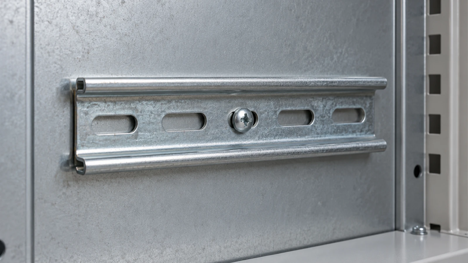
The short answer is that DIN rail mounted circuit breakers commonly use a 35 mm top-hat rail, but the rail profile and the complete device drawing must both match the design. Two familiar profiles are 35 × 7.5 mm and 35 × 15 mm. Those dimensions describe the rail, not the breaker width or depth. Breaker module width, pole arrangement, accessories, terminal position and enclosure clearance remain model-specific. Start with the manufacturer’s dimensional drawing, verify the mounting latch and rail profile, then check the entire assembly’s electrical and mechanical requirements before purchasing.
What does a 35 mm DIN rail dimension describe?
The 35 mm designation refers to the rail’s nominal profile width. The second dimension describes profile height. Phoenix Contact’s NS 35/7.5 rail product record identifies its profile with EN 60715, while its separate NS 35/15 rail record identifies the deeper alternative. The actual fixing pattern, material and length are additional procurement details.
Choosing a deeper rail changes the position of the mounted device relative to the backplate and cover. That can matter in a shallow enclosure even when the breaker clips on correctly. Confirm how the drawing measures overall depth: from the front face, mounting plane or rear envelope. Mixing these reference planes is a more common source of layout error than choosing the wrong nominal rail width.
| Dimension or interface | Lo que describe | Lo que no prueba |
|---|---|---|
| Rail profile width | Mechanical support geometry | Breaker pole width |
| Rail profile height | Backplate-to-rail offset | Enclosure depth clearance |
| Device width | Space along the rail | Busbar interchangeability |
| Terminal position | Connection alignment and access | Electrical compatibility |
| Front projection | Relationship to door and cover | Correct latch engagement |
How wide is an MCB per pole?
About 18 mm per module is a common modular-device convention, but it is not a universal guarantee for every pole or protection function. Compact 1P+N devices, RCBOs, auxiliary contacts and other accessories can follow different layouts. Use the total width in the exact model drawing rather than multiplying pole count by an assumed pitch.
A project may need a one-module neutral-switching configuration where another manufacturer’s similar electrical function occupies more space. Neither the handle count nor the product’s appearance settles that question. The relevant DIN rail size for MCB procurement record therefore includes both rail compatibility and the complete dimensional envelope, including accessories.
How much can a deeper rail move the breaker toward the door?
Consider a layout that changes from a nominal 7.5 mm-high profile to a nominal 15 mm-high profile. If the backplate and the device’s seating relationship stay the same, the nominal height difference is 7.5 mm. That extra projection can use up clearance in front of the handle or terminals even though the device width has not changed. This is a geometric illustration, not a dimensional guarantee for every rail and latch combination.
Compare both drawings from the same datum. Check the actual mounting feet, backplate fixings, latch engagement and front projection before releasing the enclosure. A drawing measured from the rail seating plane cannot be compared directly with one measured from the rear of the device. Recording the datum beside the dimension avoids a plausible-looking but incorrect fit check.
Which dimensions matter after the breaker fits the rail?
Leave enough space for conductor bends, terminal access and the manufacturer’s tightening procedure. Check whether a cable duct blocks a terminal screw or whether the enclosure door contacts a handle. A device that fits the available width can still be difficult to terminate or maintain. Cable cross-section and bend space belong in the layout review before enclosure tooling or bulk purchasing.
Record spare space deliberately. Reserve width for the accessories actually planned, such as an auxiliary contact or shunt release, rather than an arbitrary number of empty modules. A rail type circuit breaker does not establish that every accessory in the same supplier’s catalogue fits it. Compatibility must be confirmed for the specific series.
| Layout item | Document needed | Acceptance check |
|---|---|---|
| Breaker and accessories | Complete assembly drawing | Total installed width and latch access |
| Comb busbar | Approved compatibility details | Pitch, pin or fork geometry and terminal rating |
| Recinto | Door and mounting-plane drawing | Front clearance and service access |
| Cables and ducts | Wiring layout | Bend space and tightening access |
Can the breaker be removed after the panel is fully wired?
Check a service envelope as well as the static outline. With the planned ducts, covers, cables and busbar in place, can a technician reach the release latch, use the specified terminal tool and follow the manufacturer’s removal sequence? A closed-door clearance check will not answer those questions. Do not assume a rail-mounted breaker can be pulled out independently of the busbar or adjacent accessories.
Before committing to a production quantity, make the first assembly an acceptance check using the ordered breaker, accessory, compatible busbar and largest planned conductor. Review it de-energized against the manufacturers’ instructions. Record the part numbers and drawing revisions, latch access, cable bend space and cover fit. These are proposed checks for the project, not a claim that CHAC has tested every combination. Repeat the relevant checks if purchasing changes a component. Electrical sizing still needs its own review, as explained in the breaker and conductor sizing guide.
Can different manufacturers’ DIN rail breakers share a busbar?
Not merely because they fit the same rail. Busbar pitch, terminal shape, clamping arrangement, protective covers and the assembly manufacturer’s approved combinations all matter. A contact that appears to engage can still have inadequate clamping or clearance. Rail standardization concerns mounting geometry; it does not approve mixed electrical connections.
Likewise, an IEC MCB should not be treated as a replacement for a US panel breaker unless the applicable listing and panel instructions explicitly permit that installation. Confirm voltage, breaking capacity, trip curve and market requirements separately from dimensions. This separation also helps purchasing teams compare quotations that otherwise look mechanically identical.
What should a buyer request before approving the layout?
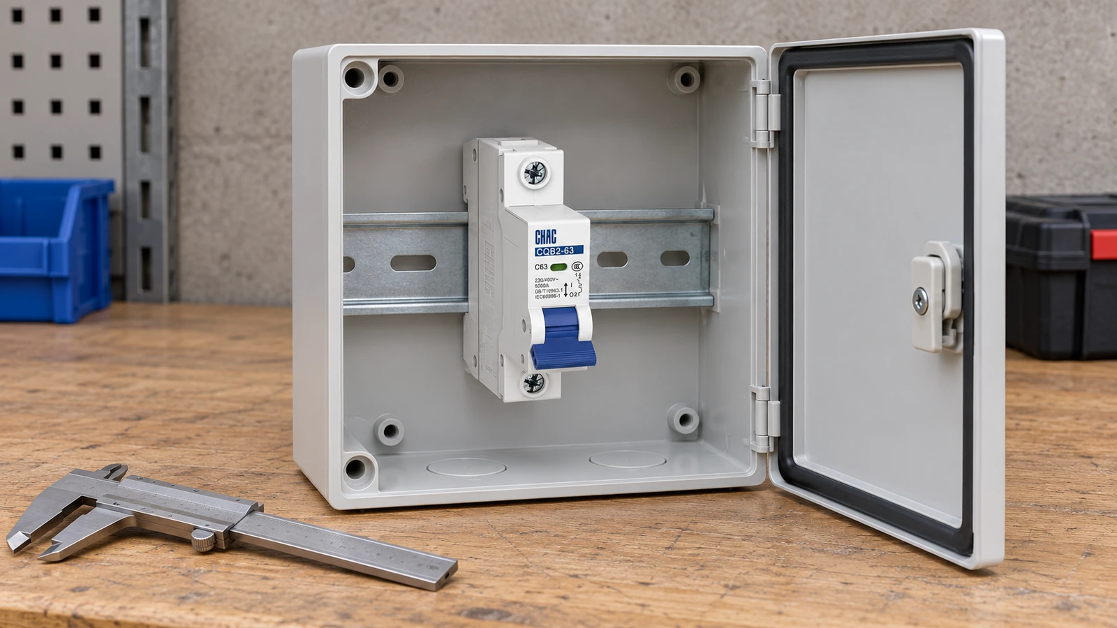
Request a model-specific drawing with width, height, depth and reference planes, plus the rail profile, conductor limits and compatible accessories. CHAC’s CQB2-63 MCB configurations include several pole arrangements and B/C/D curves. Use the ordered variant’s drawing to establish the actual space requirement. The separate PXB6-63 circuit breaker should be evaluated on its own published data, not presumed mechanically interchangeable.
For a rail-mounted meter next to the breaker, also check display visibility, wiring segregation and the meter’s individual mounting dimensions. Sharing a rail does not determine metering accuracy, communications or the protection arrangement. Keep each device’s functional specification attached to the same assembly drawing.
What else should buyers know about rail breakers?
What is a DIN rail circuit breaker?
It is a circuit breaker designed to attach to a specified mounting rail profile. The rail supports the device mechanically; its protection function and ratings come from the breaker specification.
What is a DIN-SAFE circuit breaker?
Do not treat “DIN-SAFE” as a universal breaker standard. Check whether the term is a particular trade name or an imprecise description, then verify the actual manufacturer, model and applicable standard.
What is the width of a DIN rail mounted circuit breaker per pole?
Many modular MCBs use a width near 18 mm per module, but pole count does not guarantee module count. Check the exact model drawing, especially for compact neutral arrangements and accessories.
What is the 80% rule for circuit breakers?
It is commonly used to explain conventional US continuous-load sizing conditions. It is not a DIN rail dimension rule or a universal 80% trip threshold.
What are DIN rail mounted circuit breakers used for?
They provide the protection functions specified for their model in distribution or control assemblies. Confirm voltage, current, fault rating, trip characteristic and market approval for the actual application.
How do DIN rail mounted circuit breakers work?
The mounting latch holds the breaker on the rail, while the internal protection mechanism detects the conditions specified by its design. The rail itself does not detect overload or short circuit.
Referencias
- Phoenix Contact NS 35/7.5 PERF 955MM, product 1207653; accessed October 19, 2026
- Phoenix Contact NS 35/15 PERF 1000MM, product 1207658; accessed October 19, 2026
- Cerrowire Installation Guide, conductor installation context; accessed October 19, 2026
Conclusion
Begin a DIN rail layout with the mounting profile, then work outward to the complete device envelope, terminals, accessories and enclosure. A shared 35 mm support is useful standardization, but it does not guarantee a shared busbar, identical pole widths or approval for the same electrical assembly. Keep mechanical fit and electrical suitability as separate acceptance checks. Confirm the installed combination with current drawings before committing to an enclosure or production order, and retain those drawings with the purchasing specification. CHAC can support the model-selection stage with its published breaker configurations and the technical documents for the ordered variant. A reviewed assembly layout is a stronger basis for procurement than a product photograph or nominal module count.
For the relevant model drawings and project documentation, contact CHAC with the circuit requirements.