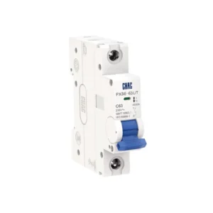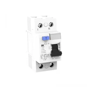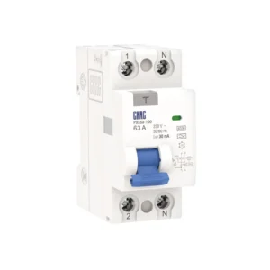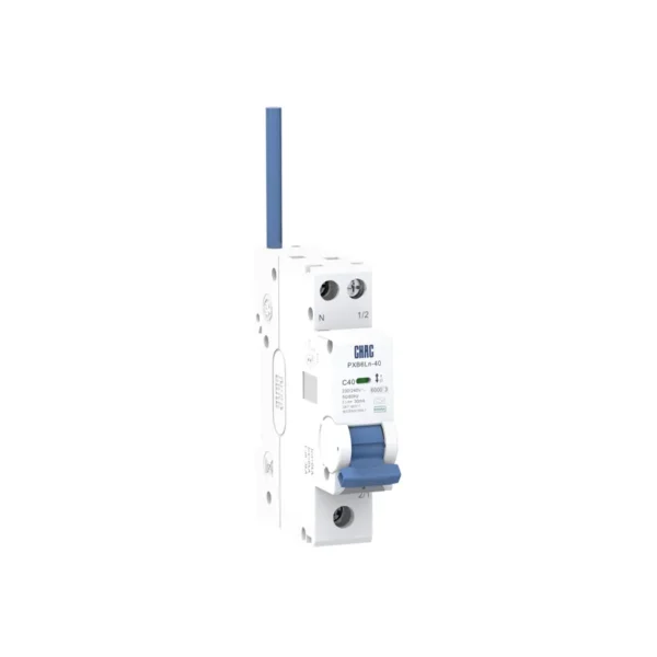
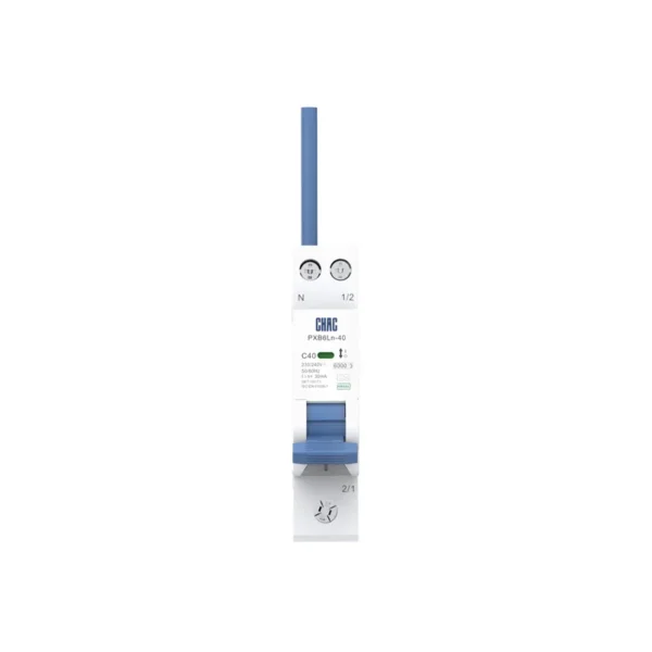
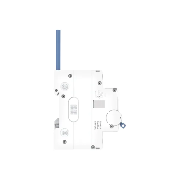
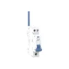
PXB6Ln-40 Electronic Residual Current Operated Circuit-Breaker with Overcurrent Protection
Características del producto
■ Enhanced Safety Design: Compact enclosure with a 1P+N configuration and simultaneous disconnection for improved maintenance safety.
■ Dual Electrical Protection: Integrated overload and short-circuit protection provides reliable basic protection for distribution circuits.
■ Safe Isolation: Reliable electrical isolation with a clearly indicated open position ensures complete circuit isolation for safe maintenance.
■ Wide Application Range: Suitable for circuit protection in industrial, commercial, high-rise residential, and household electrical systems.
Especificación de Pedido
Por favor, especifique lo siguiente al hacer un pedido:
1.Product Model: PXB6Ln-40
2.Number of Poles: 1P+N,
3.Rated Current & Tripping Curve: e.g., C/25A
- Tripping Curve (Type): B, C
- Rated Current (In): 6A, 10A, 16A, 20A, 25A, 32A,40A
4.Residual Current Operation:
- Residual Current Type: AC, A
- Rated Residual Operating Current (IΔn): 10mA, 30mA,100mA,
Quantity: e.g., 100 pcs
5.Ordering Example:
PXB6Ln-40 1P+N C/25A 30mA AC 100 pcs
Especificaciones técnicas
| Parámetro | |
| Tensión nominal | 230/240V |
| Rated Insulation Voltage(Ui) | 400V |
| Tensión Nominal de Resistencia al Impulso (Uimp) | 4000 V |
| Corriente Nominal (In) | 6、10、16、20、25、32、40 |
| Rated Residual Operating Current(IΔn) | 10、30、100mA |
| Residual Current Trip Type | AC type、A type |
| Frecuencia nominal | 50/60Hz |
| Número de polos | 1P+N |
| Rated Short-Circuit Breaking Capacity (Icn = Ics) | 6000A |
| Resistencia Mecánica | Mayor o igual a 10000 |
| Resistencia eléctrica | ≥4000 |
| Disparo Instantáneo | B、C |
| Grid Spacing | 50mm |
| Grado de Protección | IP 20 |
| Standards Compliance | IEC61009-1, GB/T 16917.1 |
| Certificación | CE CB CCC |DEKRA Certified |
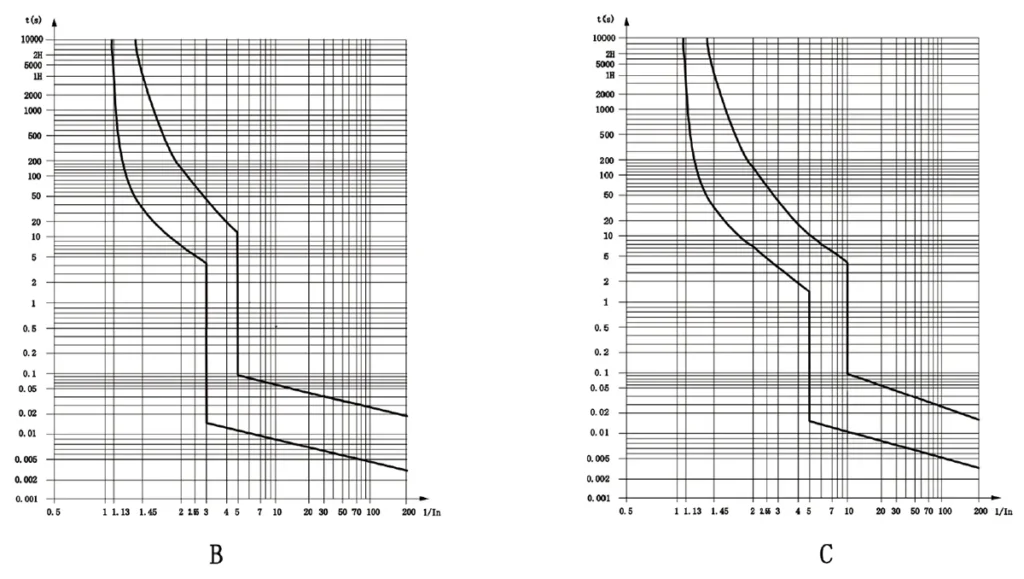
Tripping Characteristics (Reference Temperature: 30℃)
| Artículo | Curva de disparo | Corriente de prueba (A) | Estado inicial | Límite de tiempo para disparar o no disparar | Resultado esperado | Observaciones |
| a | B、C | 1.13En | Frío | t ≤ 1 h | No desatascador | La corriente sube suavemente al valor especificado en 5s |
| b | B、C | 1.45pulg | Siguiendo el ítem una prueba | t<1h | Tropezando | |
| c | B、C | 2.55In | Frío | 1s<t<60s(In≤32A) 1s<t<120s(In>32A) |
Tropezando | |
| d | B | 3En | Frío | t ≤ 0,1 s | No desatascador | Enciende la fuente de alimentación cerrando el interruptor auxiliar |
| C | 5In | |||||
| e | B | 5In | Frío | t<0.1s | Tropezando | Enciende la fuente de alimentación cerrando el interruptor auxiliar |
| C | 10 en |
Note: The :erm “cold” means that the test is carried out at at a reference calibration temperature without load before the test.
Requisitos del conductor y sección transversal
| Sección transversal de cobre (mm²) | Corriente nominal In(A) |
| 1 | En≤6 |
| 1.5 | 6<In≤13 |
| 2.5 | 13<In≤20 |
| 4 | 20<In≤25 |
| 6 | 25<In≤32 |
| 10 | 32<In≤40 |
Designación del tipo
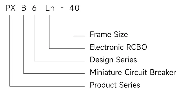
Curvas de disparo
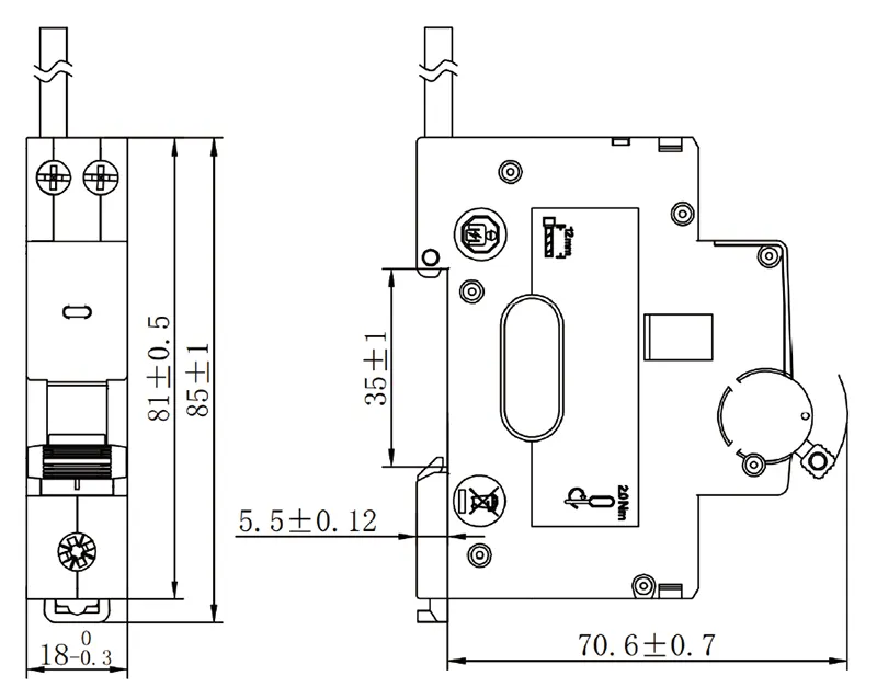
Dimensiones(mm)