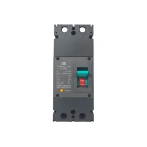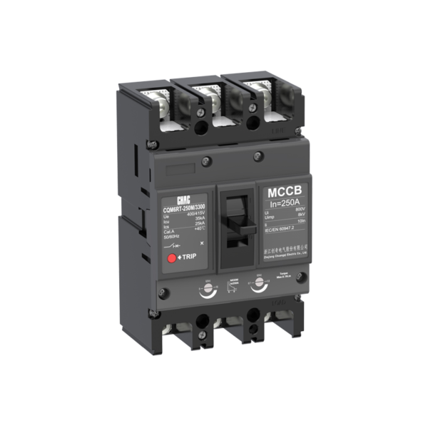
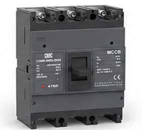
CQM6RT MCCB thermostatique et magnétique réglable - Fabricant OEM
Le CQM6RT MCCB fournit une protection réglable contre les surcharges et les courts-circuits dans sa plage 32–1250A publiée. La spécification doit tenir compte de la tension du système, de la charge, de la coordination des conducteurs, du courant de défaut présumé et des règles applicables, et non pas uniquement de la valeur en ampères.
Vue d'ensemble du produit
CQM6RT est un disjoncteur thermomagnétique destiné aux applications de distribution et de protection en courant alternatif 400/415V. Sa gamme publiée s’étend de 32 à 1250A, avec des options 3P / 4P. Le choix dépend de la conception complète du système électrique, notamment du niveau de court-circuit, de la coordination, de l’ampacité des conducteurs, des conditions d’encapsulation et des réglementations locales.
La spécification produit fournie fait référence aux normes IEC/EN 60947-1, IEC/EN 60947-2, IEC/EN 60947-3 et IEC/EN 60947-4, ainsi qu’aux normes GB/T 14048.1, .2, .3 et .4. Ces références normatives ne constituent pas, à elles seules, une certification pour une commande particulière.
Principales caractéristiques
Applications typiques
Les applications typiques comprennent les alimentateurs industriels et les circuits de moteurs pour lesquels la coordination en champ nécessite des réglages de déclenchement ajustables. Il s’agit de contextes d’évaluation et non de homologations universelles. Vérifiez avec précision le boîtier, la tension, la capacité de coupure, le déclencheur, les accessoires et la méthode d’installation avant toute spécification.
Demandes d’admission et guide de sélection
Utilisez les valeurs CQM6RT vérifiées ci-dessous pour établir une liste restreinte, puis validez le circuit complet. Le calibre d’un disjoncteur modulaire (MCCB) ne remplace pas les calculs des conducteurs, l’analyse du courant de défaut, l’examen de la coordination ou les exigences locales d’installation.
| Point de sélection | Référence CQM6RT | Ce que le projet doit confirmer |
|---|---|---|
| Courant nominal | 32–1250A | Courant de conception, ampacité des conducteurs, mode d’installation, température et regroupement |
| Tension | AC 400/415V | Système d’alimentation et dimensionnement des équipements |
| Pôles | 3P / 4P | Conducteurs sous tension et traitement du neutre |
| Voyage / protection | Imagerie thermique IR et imagerie magnétique IM réglables | Profil de charge, réponse aux défauts et coordination |
| Capacité de rupture | Classes C/S/M/H jusqu'à 75kA, selon le châssis et la configuration commandée | Courant de court-circuit prévisionnel au point d’installation |
Protection fixe vs réglable
Un dispositif thermomagnétique fixe peut convenir à une conception stable, tandis qu’un déclencheur réglable peut faciliter la coordination lorsque l’étude de projet nécessite des réglages sur site.
Trip Coordination
Compare MCCB Options →
Disjoncteur modulaire (MCCB) vs Disjoncteur miniature (MCB)
An MCCB is normally evaluated for higher current, fault duty or accessory flexibility; an MCB may be more suitable for compact final circuits.
Current & Fault Duty
Compare MCCB and MCB →
Icu vs Ics
The saved data for CQM6RT lists C/S/M/H classes up to 75kA, according to frame and ordered configuration. Match the declared duty to the prospective short-circuit current and continuity objective.
Short-Circuit Study
Review Technical Support →
Pole and Neutral Arrangement
Published pole options are 3P / 4P. Confirm which conductors must be switched, protected and isolated together.
System Arrangement
View MCCB Range →
Guide d'achat
- State the exact model: CQM6RT.
- Provide frame and rated current within the published range: 32–1250A.
- Confirm poles: 3P / 4P.
- Specify the trip unit or protection function: adjustable thermal Ir and magnetic Im.
- Provide system voltage, frequency, application, expected fault level, destination market and quantity.
- List required accessories, terminals, documents and any approved OEM/ODM marking or packaging requirements.
Examens d’installation et de coordination
- Use the exact model drawing and instructions; do not infer terminal positions, supply direction or accessory compatibility from another MCCB.
- Verify conductor material and cross-section against the circuit calculation, terminal data, temperature and grouping.
- Confirm Icu/Ics or DC fault duty, upstream/downstream coordination, enclosure conditions, altitude and clearances.
- Installation, isolation, testing and maintenance must be performed by qualified personnel under applicable rules.
Guide de sélection

| Product code ① | Shell frame grade ② | Shell frame grade ③ | Breaking capacity ④ | ||||
|---|---|---|---|---|---|---|---|
| CQM6 | RT | 160 | C | ||||
| Disjoncteur à boîtier moulé | RT stands for thermomagnetic ally adjustable T、A stands for single adjustable (i.e.,thermally adjustable/magnetically fixed). |
C | S | M | H | ||
| 160 | 160 | 25/18 | 35/25 | 50/35 | / | ||
| 250 | 250 | 25/18 | 35/25 | 50/35 | / | ||
| 400 | 400 | / | 35/25 | 50/35 | 75/50 | ||
| 630 | 630 | / | 35/25 | 50/35 | 75/50 | ||
| 800 | 800 | / | 35/25 | 50/35 | 75/50 | ||
| 1250 | 1250 | / | 35/25 | 50/35 | 75/50 | ||
| Operating method⑤ | Number of poles⑥ | Trip Unit &Accessories⑦ | Rated current A | |
|---|---|---|---|---|
| P | 4 | 300 | 125A | |
| P:Motorized operation Z:Turn the handle W:Direct operation DElectric operation DC1 DC 2,DC3 |
160A:3P,4P 250A:3P,4P 400A:3P,4P 630A:3P,4P 800A:3P,4P 1250A:3P,4P |
The first digit indicates the type of detent 2:Instantaneous detent only 3:Duplicate detent Note:The last two digits are the accessory designator(see accessory table). |
160 | 32,40,50,63,80,100,125,140,160 |
| 250 | 100,125,140,160,180,200,225,250 | |||
| 400 | 250,315,350,400 | |||
| 630 | 250,315,350,400,500,630 | |||
| 800 | 500,630,700,800 | |||
| 1250 | 800,1000,1250 | |||
| Application⑧ | Optional code for Level 4 products⑨ | Special code⑩ |
|---|---|---|
| 2 | A | I |
| 1:For power distribution | A:N-pole unprotected,not combinable A | I:Overload alarm non trip function |
| 2:For motor protection | B:N-pole unprotected,combinable |
| Accessory Voltage ⑪ | Motorized operating voltage ⑫ | Installation ⑬ | Terminal Block Option ⑭ | |||
|---|---|---|---|---|---|---|
| Q1 | D1 | Q | 2 | |||
| Undervoltage detent UVT Q1:AC220V Q2:AC240V Q3:AC380V Q4:AC415V |
Shunt release Shunt F1:AC220V F2:AC380V F3:DC110V F4:DC24V |
Auxiliary alarm Auxiliary J1:AC125V J2:AC250V J3:DC125V J4:DC24V |
CD1 D1:AC220V D2:AC230V D3:AC380V D4:AC400V |
CD2 D5:AC230V D6:AC110V D7:DC220V D8:DC110V D9:AC110~240V D10:DC100~220V |
Q:Front of plate H:Rear of plate C:Inserted |
1:No installation 2:Installation |
| Note:When motorized operation is selected,please refer to the external accessories for the two voltages applicable for motorized operation. | ||||||
Accessory List
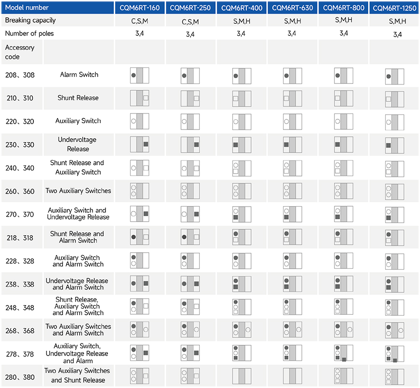
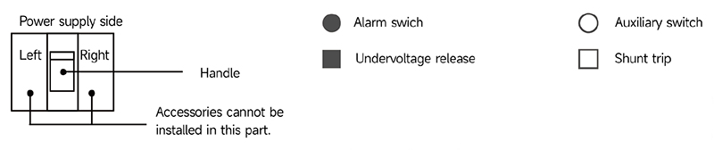
CHAC offers a right-side auxiliary switch, a left-side shunt release and a left-side undervoltage release.
For accessory codes 220, 320, 240, 340, 270 and 370, specify the required auxiliary contact arrangement when ordering.
Main Technical Parameters
| Model number | CQM6RT-160 | CQM6RT-250 | ||||||
|---|---|---|---|---|---|---|---|---|
| Rated current of frame level Inm(A) | 160 | 250 | ||||||
| Nombre de poteaux | 3,4 | 3,4 | ||||||
| Rated current In(A),at 40°C,50°C,55°C | 32,40,50,63,80,100,125,140,160 | 100,125,140,160,180,200,225,250 | ||||||
| Rated operating voltage Ue(V),AC 50/60Hz | 400/415 | 400/415 | ||||||
| Rated insulation voltage Ui (V) | 800 | 800 | ||||||
| Rated impulse withstand voltage Uimp(KV) | 8 | 8 | ||||||
| Breaking capacity designation | C | S | M | C | S | M | ||
| Short-circuit breaking capacity Icu/Ics(kA) | AC400/415V | 25/18 | 35/25 | 50/35 | 25/18 | 35/25 | 50/35 | |
| Selectivity category | A | A | A | A | A | A | ||
| Number of operating cycles ON (cycle) |
ON | 6000 | 6000 | |||||
| OFF | 10000 | 10000 | ||||||
| Trip mechanisms and protection types | Magnetic trip | Power distribution protection | ● | ● | ● | ● | ● | ● |
| Protection du moteur | ● | ● | ● | ● | ● | ● | ||
| Thermal-magnetic trip | Power distribution protection | ● | ● | ● | ● | ● | ● | |
| Protection du moteur | ● | ● | ● | ● | ● | ● | ||
| Accessoire | Auxiliary contacts | ● | ● | ● | ● | ● | ● | |
| Alarm contacts | ● | ● | ● | ● | ● | ● | ||
| Shunt disconnect | ● | ● | ● | ● | ● | ● | ||
| Undervoltage detent | ● | ● | ● | ● | ● | ● | ||
| Manual operating mechanism | ● | ● | ● | ● | ● | ● | ||
| Motorized operating mechanism | ● | ● | ● | ● | ● | ● | ||
| Backplane wiring | ● | ● | ● | ● | ● | ● | ||
| Inserted | ● | ● | ● | ● | ● | ● | ||
| Coupling plate | ● | ● | ● | ● | ● | ● | ||
| Partition between phases | ● | ● | ● | ● | ● | ● | ||
| Derivative products | Dedicated for prepayment electric meters | ● | ● | ● | ● | ● | ● | |
| Overload alarm without trip | ● | ● | ● | ● | ● | ● | ||
| Overall dimensions (mm) (a-b-c-ca) | 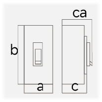 |
3 P | 90×155×71×95 | 90×155 ×85×109 | 105×165×71×96 | 105×165 ×93×119 | ||
| 4 P | 120×155×71×95 | 120×155 ×85×109 | 140×165×71×96 | 140×165 ×93×119 | ||||
Note: ● indicates an available optional accessory; – indicates that the accessory is not available.
| Model number | CQM6RT-400 | CQM6RT-630 | ||||||
|---|---|---|---|---|---|---|---|---|
| Rated current of frame level Inm(A) | 400 | 630 | ||||||
| Nombre de poteaux | 3,4 | 3,4 | ||||||
| Rated current In(A),at 40°C,50°C,55°C | 250,315,350,400 | 250,315,350,400,630 | ||||||
| Rated operating voltage Ue(V),AC 50/60Hz | 400/415 | 400/415 | ||||||
| Rated insulation voltage Ui (V) | 800 | 800 | ||||||
| Rated impulse withstand voltage Uimp(KV) | 8 | 8 | ||||||
| Breaking capacity designation | S | M | H | S | M | H | ||
| Short-circuit breaking capacity Icu/Ics(kA) | AC400/415V | 35/25 | 50/35 | 75/50 | 35/25 | 50/35 | 75/50 | |
| Selectivity category | A | A | A | A | A | A | ||
| Nombre de cycles de fonctionnement (cycle) |
ON | 3000 | 3000 | |||||
| OFF | 8000 | 8000 | ||||||
| Trip mechanisms and protection types | Magnetic trip | Power distribution protection | ● | ● | ● | ● | ● | ● |
| Protection du moteur | ● | ● | ● | ● | ● | ● | ||
| Thermal-magnetic trip | Power distribution protection | ● | ● | ● | ● | ● | ● | |
| Protection du moteur | ● | ● | ● | ● | ● | ● | ||
| Accessoire | Auxiliary contacts | ● | ● | ● | ● | ● | ● | |
| Alarm contacts | ● | ● | ● | ● | ● | ● | ||
| Shunt disconnect | ● | ● | ● | ● | ● | ● | ||
| Undervoltage detent | ● | ● | ● | ● | ● | ● | ||
| Manual operating mechanism | ● | ● | ● | ● | ● | ● | ||
| Motorized operating mechanism | ● | ● | ● | ● | ● | ● | ||
| Backplane wiring | ● | ● | ● | ● | ● | ● | ||
| Inserted | ● | ● | ● | ● | ● | ● | ||
| Coupling plate | ● | ● | ● | ● | ● | ● | ||
| Partition between phases | ● | ● | ● | ● | ● | ● | ||
| Derivative products | Dedicated for prepayment electric meters | ● | ● | ● | ● | ● | ● | |
| Overload alarm without trip | ● | ● | ● | ● | ● | ● | ||
| Overall dimensions (mm) (a-b-c-ca) | |
3 P | 140×257×108×156 | 140×257×108×156 | ||||
| 4 P | 185×257×108×156 | 185×257×108×156 | ||||||
Note: ● indicates an available optional accessory; – indicates that the accessory is not available.
| Model number | CQM6RT-800 | CQM6RT-1250 | ||||||
|---|---|---|---|---|---|---|---|---|
| Rated current of frame level Inm(A) | 800 | 1250 | ||||||
| Nombre de poteaux | 3,4 | 3,4 | ||||||
| Rated current In(A),at 40°C,50°C,55°C | 500,630,700,800 | 800,1000,1250 | ||||||
| Rated operating voltage Ue(V),AC 50/60Hz | 400/415 | 400/415 | ||||||
| Rated insulation voltage Ui (V) | 800 | 800 | ||||||
| Rated impulse withstand voltage Uimp(KV) | 8 | 8 | ||||||
| Breaking capacity designation | S | M | H | S | M | H | ||
| Short-circuit breaking capacity Icu/Ics(kA) | AC400/415V | 35/25 | 50/35 | 75/50 | 35/25 | 50/35 | 75/50 | |
| Selectivity category | A | A | A | A | A | A | ||
| Nombre de cycles de fonctionnement (cycle) |
ON | 1000 | 1000 | |||||
| OFF | 3000 | 3000 | ||||||
| Trip mechanisms and protection types | Magnetic trip | Power distribution protection | ● | ● | ● | ● | ● | ● |
| Protection du moteur | ● | ● | ● | ● | ● | ● | ||
| Thermal-magnetic trip | Power distribution protection | ● | ● | ● | ● | ● | ● | |
| Protection du moteur | ● | ● | ● | ● | ● | ● | ||
| Accessoire | Auxiliary contacts | ● | ● | ● | ● | ● | ● | |
| Alarm contacts | ● | ● | ● | ● | ● | ● | ||
| Shunt disconnect | ● | ● | ● | ● | ● | ● | ||
| Undervoltage detent | ● | ● | ● | ● | ● | ● | ||
| Manual operating mechanism | ● | ● | ● | ● | ● | ● | ||
| Motorized operating mechanism | ● | ● | ● | ● | ● | ● | ||
| Backplane wiring | ● | ● | ● | – | – | – | ||
| Inserted | ● | ● | ● | – | – | – | ||
| Coupling plate | ● | ● | ● | ● | ● | ● | ||
| Partition between phases | ● | ● | ● | ● | ● | ● | ||
| Derivative products | Dedicated for prepayment electric meters | ● | ● | ● | ● | ● | ● | |
| Overload alarm without trip | ● | ● | ● | ● | ● | ● | ||
| Overall dimensions (mm) (a-b-c-ca) | |
3 P | 210×275×114×163 | 210×275×114×163 | ||||
| 4 P | 280×275×114×163 | 280×275×114×163 | ||||||
Note: ● indicates an available optional accessory; – indicates that the accessory is not available.
Caractéristiques de fonctionnement
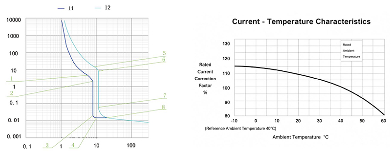
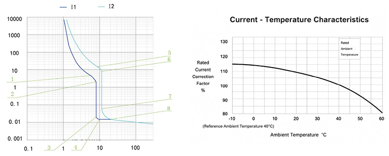
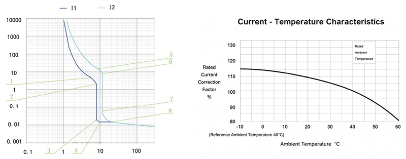
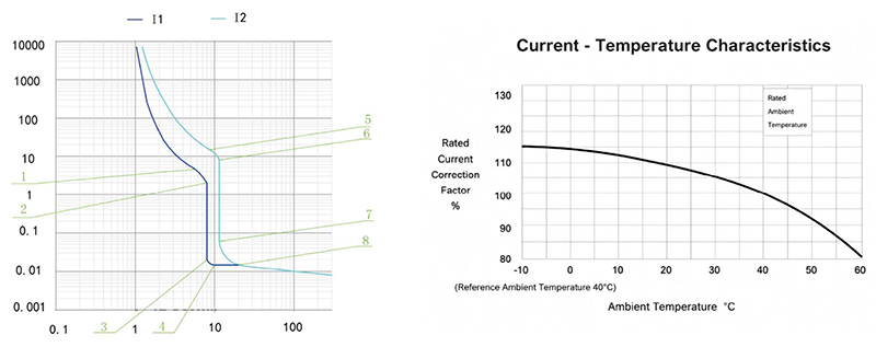
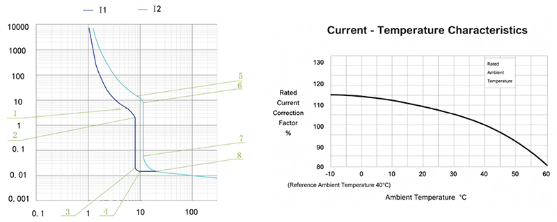
The following table gives the inverse-time operating characteristics for distribution protection with all poles energised at an ambient temperature of +40°C, without humidity compensation.
| Test current designation | Setting current multiple | Conventional time | Initial state |
|---|---|---|---|
| In≤63 In > 63 | |||
| Conventional non-tripping current | 1.05 | ≥1h ≥2h | Cool state |
| Conventional tripping current | 1.30 | <1h<2h | Hot state |
The following table gives the inverse-time operating characteristics for motor protection with all poles energised at an ambient temperature of +40°C, without humidity compensation.
| Test current designation | Setting current multiple | Conventional time | Initial state |
|---|---|---|---|
| In≤800 | |||
| Conventional non-tripping current | 1.0 | ≥2h | Cool state |
| Conventional tripping current | 1.2 | <2h | Hot state |
The operating-characteristics reference gives an instantaneous trip current setting of 10In for distribution protection. Confirm the applicable trip-unit setting for the ordered configuration.
The operating-characteristics reference gives an instantaneous trip current setting of 12In for motor protection.
The stated accuracy of the instantaneous trip current setting is 20% of the setting value.
CQM6RT-160 Operating Characteristic Curve
CQM6RT-250 Operating Characteristic Curve
CQM6RT-400 / 630 Operating Characteristic Curve
CQM6RT-800 Operating Characteristic Curve
CQM6RT-1250 Operating Characteristic Curve
Dimensions d'ensemble et de montage (mm)
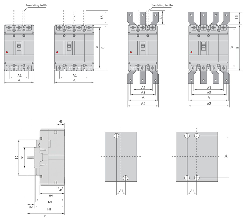
| Disjoncteur à boîtier moulé | Dimension globale | Dimensions d'installation | Boit | |||||||||||||||||||||
|---|---|---|---|---|---|---|---|---|---|---|---|---|---|---|---|---|---|---|---|---|---|---|---|---|
| A | A1 | A2 | A3 | B | B1 | B2 | B3 | B5 | B6 | H | H1 | H2 | H3 | H4 | H5 | H6 | A4 | B4 | ||||||
| 3P | 4P | 3P | 4P | 3P | 4P | 3P | 4P | |||||||||||||||||
| CQM6RT-160CS | 90 | 120 | 60 | 90 | – | – | – | – | 155 | 134 | 103 | 50 | 48 | – | 95 | 76 | 2.2 | 70.7 | 62.3 | 23.8 | 24.6 | 30 | 132 | M8 |
| CQM6RT-160M | 90 | 120 | 60 | 90 | – | – | – | – | 155 | 134 | 103 | 50 | 48 | – | 109.2 | 90 | 2.2 | 84.9 | 76.4 | 23.1 | 24.9 | 30 | 132 | M8 |
| CQM6RT-250CS | 105 | 140 | 70 | 105 | – | – | – | – | 165 | 144 | 102 | 50 | 97 | – | 95.8 | 75 | 2.8 | 71 | 62.2 | 22.7 | 23.3 | 35 | 126 | M8 |
| CQM6RT-250M | 105 | 140 | 70 | 105 | – | – | – | – | 165 | 144 | 102 | 50 | 95 | – | 118.6 | 97.6 | 2.8 | 93.4 | 84.5 | 23.1 | 23.2 | 35 | 126 | M8 |
| CQM6RT-400 | 140 | 185 | 88 | 132 | 140 | 196 | 112 | 168 | 257 | 230 | 179 | 90 | 103 | 42 | 156 | 112.1 | 3.5 | 107.5 | 99.6 | 30.9 | 32 | 44 | 194 | M10 |
| CQM6RT-630 SMH 400A | 140 | 185 | 88 | 132 | 140 | 196 | 112 | 168 | 257 | 230 | 179 | 90 | 103 | 42 | 156 | 112.1 | 3.5 | 107.5 | 99.6 | 30.9 | 34 | 44 | 194 | M10 |
| CQM6RT-630 SMH 630A | 140 | 185 | 88 | 132 | 140 | 196 | 112 | 168 | 257 | 230 | 179 | 90 | 103 | 42 | 156 | 112.1 | 3.5 | 107.5 | 99.6 | 33.4 | 30.7 | 44 | 194 | M10 |
| CQM6RT-800 SMH 630A | 210 | 280 | 140 | 210 | 180 | 250 | 140 | 210 | 275 | 243 | 192 | 90 | 103 | 87 | 162.5 | 118.4 | 2.7 | 114.3 | 106 | 28.5 | 32.7 | 70 | 242.5 | M12 |
| CQM6RT-800 SMH 800A | 210 | 280 | 140 | 210 | 180 | 250 | 140 | 210 | 275 | 243 | 192 | 90 | 103 | 87 | 162.5 | 118.4 | 2.7 | 114.3 | 106 | 29.5 | 34.7 | 70 | 242.5 | M12 |
| CQM6RT-1250 SMH | 210 | 280 | 140 | 210 | 180 | 250 | 140 | 210 | 275 | 243 | 192 | 90 | 103 | 87 | 162.5 | 118.4 | 2.7 | 114.3 | 106 | 31.5 | 32 | 70 | 242.5 | M10 |
Pourquoi choisir CHAC
Avec plus de 30 ans d'expérience dans la fabrication, 1100 employés et 100 millions de poteaux
Avec une capacité annuelle de 90% machines automatisées, CHAC garantit une production stable et rigoureuse.
contrôle qualité pour les clients OEM/ODM mondiaux. Notre système de fabrication interne permet une collaboration à long terme.
Coopération pour les marques électriques, les importateurs et les distributeurs.

30+
ANNÉE D'EXPÉRIENCE
Spécialisée dans la fabrication d'appareils électriques à faible tension

1100+
EMPLOYÉS
Une équipe professionnelle garantit une qualité et une livraison stables

100 millions d'euros
Capacité annuelle des poteaux
Capacité de production à grande échelle pour répondre à la demande mondiale

90%
PRODUCTION AUTOMATIQUE
Une automatisation avancée pour une efficacité et une cohérence élevées

Ligne de montage automatisée

Laboratoire d'essai
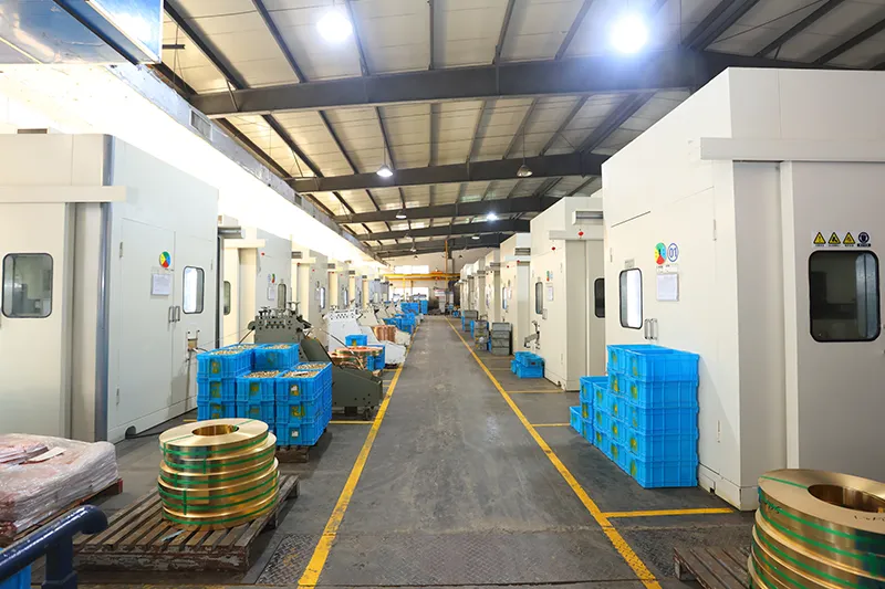
Injection et estampage
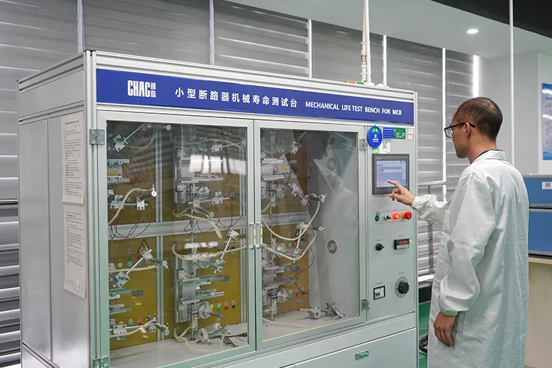
Inspection de qualité



Un système de contrôle qualité strict assure que chaque produit respecte les normes internationales.
Qu'est-ce que nous pouvons personnaliser ?
For CQM6RT projects, CHAC can review private-label marking, packaging, approved appearance options, published 32–1250A electrical configurations and technical-document requirements. Requests outside the published range are subject to engineering evaluation, testing, minimum order quantity and project feasibility.

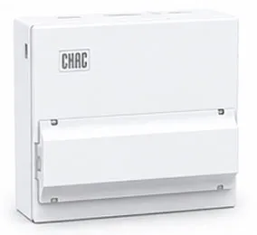
Enclos
Design
Dimensions, structures et détails d’installation sur mesure.

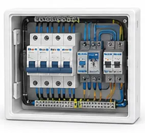
Intérieur
Configuration
Options de configuration internes et de disposition des composants flexibles.

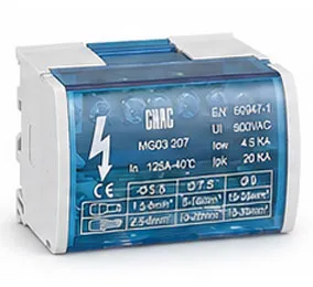
Branding et
Logo
Logos de marque privée, plaques d'identification et identité de marque.

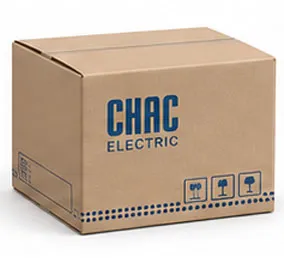
Emballage
Design
Cartons, étiquettes, manuels et solutions d'emballage personnalisés.

Électrique
Configuration
Configuration électrique adaptée en fonction des besoins de l’application.

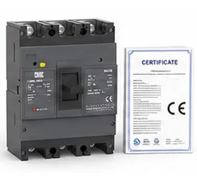
Certification
Support
Support aux normes et aux exigences de conformité propres au marché cible.
Télécharger
Disjoncteur à boîtier moulé de la série CQM6
Vue d'ensemble complète des produits pour les composants électriques à basse tension et référence de sélection de produit.
Dois-je avoir des documents techniques ?
Contactez-nous pour obtenir des fiches techniques, des certificats, des dessins, des conseils de sélection ou une assistance pour des projets OEM/ODM.
CQM6RT Product FAQ
What is the CQM6RT MCCB used for?
The CQM6RT is specified for adjustable overload and short-circuit protection in AC 400/415V systems within the published 32–1250A range. Suitability depends on the fault study, conductor coordination, enclosure and local rules.
How does the CQM6RT molded case circuit breaker work?
The protection mechanism responds to the fault conditions stated for this model: adjustable overload and short-circuit protection. Trip behaviour, settings and interruption duty must be checked against the ordered frame and product instructions.
How do I choose the CQM6RT rated current and poles?
Start with the design current and conductor calculation, then choose a published current within 32–1250A and poles from 3P / 4P. Neutral treatment, fault level, ambient conditions and coordination also need review.
What breaking capacity should I check on the CQM6RT?
Use the declared C/S/M/H classes up to 75kA, according to frame and ordered configuration for the exact frame, voltage and configuration. The prospective short-circuit current at the installation point must be within the applicable duty; a larger ampere value alone is not a selection rule.
Can the CQM6RT replace an MCB or an earth-leakage device?
An MCCB is not automatically a like-for-like replacement. The CQM6RT provides adjustable overload and short-circuit protection; residual-current protection, DC interruption, adjustable settings and other functions must be confirmed separately from the project requirement.
How should the CQM6RT be installed and tested?
Use only the exact model drawing, terminal identification and accessory instructions. A qualified person should verify isolation, conductor size, torque, clearances, settings, fault duty and functional tests before energising the circuit.
Confirm the Right CQM6RT Configuration
Send the frame, rated current, poles, protection function, system voltage, expected fault level, destination market and quantity. CHAC will review the request against the published model range.