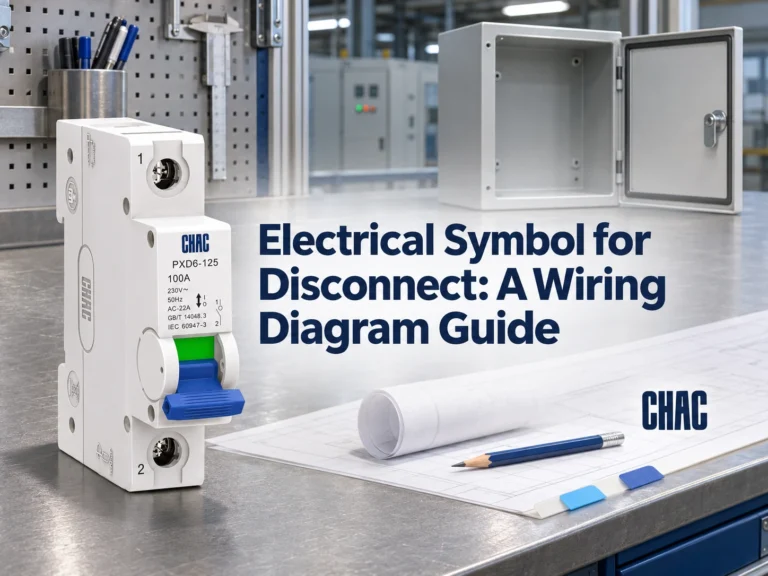
Una marcatura 10kA non costituisce una raccomandazione universale per l’aggiornamento, e un dispositivo 6kA non è automaticamente inadatto a un edificio moderno. La decisione dipende dalla corrente di guasto prevista nel punto di installazione dell’interruttore, confrontata nelle stesse condizioni di tensione e secondo gli standard di prodotto. La curva, la corrente di carico e la compatibilità con il quadro rimangono verifiche separate. Questa guida spiega cosa significano le due classificazioni, quando conta una combinazione a monte testata e perché sia la capacità massima di interruzione dei guasti sia l’efficace interruzione dei guasti devono essere riportate nella documentazione di selezione.
La risposta breve è: In un 6kA vs MCB da 10kA decisione, la capacità nominale di interruzione del sezionatore deve essere almeno uguale alla corrente di corto circuito prevista nel punto di installazione, secondo la norma e le regole di progetto applicabili. Una classificazione 6kA corrisponde a 6,000A e una classificazione 10kA a 10,000A in condizioni di prova definite; nessuno dei due valori descrive la corrente di carico normale. Calcolare o misurare il livello di guasto, verificare la tensione e la norma, e accertare qualsiasi disposizione di protezione a monte prima di approvare il dispositivo.
Cosa Significano Effettivamente 6kA e 10kA?
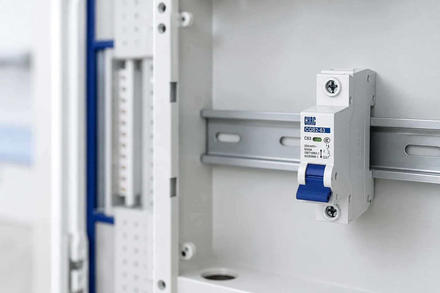
La capacità di interruzione dell'interruttore automatico in scatola stampata è la corrente di guasto che un interruttore magnetotermico miniaturizzato è classificato per interrompere in modo sicuro secondo una specifica sequenza di prova. Per impianti AC domestici e simili, IEC 60898-1 utilizza la capacità nominale di corto circuito Icn. Un numero stampato sulla parte anteriore ha quindi significato solo se associato alla tensione del dispositivo, allo standard di prodotto, ai poli e alla documentazione del produttore.
La capacità di interruzione non è uguale alla corrente nominale né alla curva di scatto. Un MCB 32A protegge un circuito che trasporta decine di ampere in condizioni normali; la sua marcatura 6kA o 10kA si riferisce a un raro cortocircuito che coinvolge migliaia di ampere. Allo stesso modo, le curve B, C e D descrivono gli intervalli di scatto istantaneo, e non il guasto massimo che il dispositivo può interrompere.
Perché il livello di cortocircuito nel punto di installazione determina la scelta?
La corrente di corto circuito prevista è la corrente che fluirebbe in una determinata posizione attraverso un guasto a impedenza trascurabile, prima della limitazione operata dai dispositivi di protezione. In genere risulta più elevata in prossimità di una sorgente a bassa impedenza e più bassa dopo lunghi tratti di cavo. L’impedenza del trasformatore, le sorgenti in parallelo, la sezione, il materiale e la lunghezza dei conduttori influiscono tutti sul risultato.
Calcolare o misurare direttamente presso il punto di installazione dell’interruttore: una cabina principale e una cabina remota per i circuiti finali possono presentare livelli di cortocircuito molto diversi. Utilizzare un calcolo della corrente di cortocircuito basato sull’impedenza oppure uno strumento idoneo per la misura del loop/PSC, secondo il metodo previsto dal progetto; registrare la tensione, l’apporto della sorgente, la configurazione di funzionamento, le ipotesi e la data.
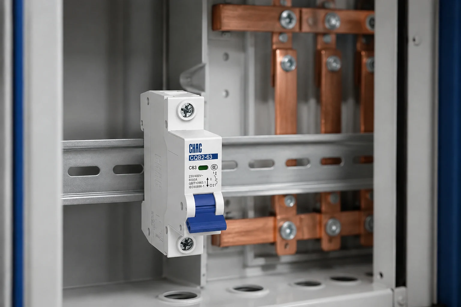
Trasformatori, generatori, collegamenti di sbarra o potenziamenti delle linee possono modificare la corrente di corto circuito. Un costo iniziale contenuto può diventare elevato se comporta riprogettazioni, sostituzioni o fermi impianto; un margine di sicurezza nelle specifiche riduce il rischio, ma non può mai sostituire i dati di prova.
Come si confrontano le opzioni 6kA e 10kA?
| Dimensioni della decisione | MCB da 6kA | MCB da 10kA |
|---|---|---|
| Capacità nominale di cortocircuito | 6,000 nelle condizioni standard e di prova indicate | 10,000 nelle condizioni standard e di prova indicate |
| Possibile contesto | Verified point fault level within 6kA | Verified level above 6kA but within 10kA |
| Design margin | Less headroom for system changes | More headroom; study still required |
| La tendenza dei costi unitari | Often lower, subject to configuration and market | Often higher because of greater interruption duty |
| Compatibilità | Voltage, poles, curve, assembly, and destination requirements must match | |
| Back-up protection | Requires manufacturer combination data | |
| Lifecycle effect | Economical when verified | May reduce upgrade risk; overspecification still costs more |
How does a short-circuit current calculation guide the choice?
For a simplified balanced three-phase fault, a short-circuit current formula is Isc = U20 / (√3 × |ZT|), where U20 is the source’s no-load line-to-line voltage and ZT is the total upstream per-phase impedance referred to that voltage level. Schneider Electric’s three-phase short-circuit calculation guide explains how network, transformer and conductor resistance and reactance enter this calculation.
As an illustrative calculation only, if U20 is 400 V and the assessed impedance magnitude is 0.040 Ω, the equation gives approximately 5.77 kA. Those assumed inputs are not site measurements or a recommendation to select a 6 kA breaker. The responsible designer must account for the applicable calculation method, source conditions, tolerances and all relevant fault contributions before approving a rating.
Calculating prospective short-circuit current at a downstream board requires that board’s supply path. A transformer-terminal result should not be copied unchanged through an arbitrary cable run. Keep the utility fault data, transformer information, conductor details and supply operating mode with the study. Review maximum current for breaking duty and minimum current for required disconnection performance.
Is the peak short-circuit current the same as the kA breaking rating?
No. A peak short-circuit current formula addresses a different quantity from the RMS AC-component value used for the relevant breaking rating. The asymmetrical peak depends on circuit conditions; a single universal multiplier is not an adequate study. Compare like quantities and separately review making or withstand duties where applicable. The MCB and MCCB rating comparison helps distinguish Icn, Icu and Ics before supplier quotations are compared.
When can upstream protection support a lower-rated MCB?
A current-limiting upstream fuse or breaker can reduce peak current and let-through energy, expressed as I²t. That does not automatically reduce the prospective current used for a standalone downstream rating. A lower-rated MCB is acceptable in a cascading arrangement only when the manufacturer has verified the exact combination, voltage, fault level, and standard.
Back-up protection shows that two devices can clear a high fault safely. Selectivity aims for the downstream device alone to operate so healthy circuits remain energized. A combination may provide back-up protection without full selectivity, increasing downtime.
Do not infer coordination from individual ratings or generic I²t data. Check both models, settings, voltage, fault range, and the manufacturer table. If the combination is unlisted, use the downstream standalone rating or obtain project-specific verification.
Which option fits the verified fault level?
| Evidence at the breaker location | 6kA option | 10kA option | Required action |
|---|---|---|---|
| Fault level below 6kA | May be suitable | May add headroom | Verify all ratings and project rules |
| Above 6kA, up to 10kA | Not suitable standalone | May be suitable | Confirm the value and documents |
| Above 10kA | Not suitable standalone | Not suitable standalone | Use higher capacity or verified coordination |
| Unknown or changing | Do not approve | Rating alone is insufficient | Complete the fault-current study |
| Upstream back-up proposed | Possible only within a tested combination | Retain the manufacturer table and study in the project file | |
Which standard and voltage must the ratings share?
IEC 60898-1 covers overcurrent circuit breakers for household and similar installations and defines ratings and test sequences. It is a product standard, not a certification. IEC 60947-2 covers circuit breakers within low-voltage switchgear and controlgear and uses concepts such as Icu and Ics. Do not compare “10kA” markings across standards without reviewing the test basis. A quotation for a 10 kAIC circuit breaker therefore needs its standard and voltage stated before comparison with an IEC-rated 10 kA MCB. If the supplier uses breaking current, confirm that it means the declared short-circuit interrupting rating, not the current that triggers the trip mechanism.
IEC 60364-4-43 addresses installation protection against overcurrent. In North America, adopted NFPA 70 and local rules govern installation; OSHA 1910.303(b)(4) requires interrupting equipment to be rated for nominal voltage and available current. Unsupported claims can delay approval and force replacement.
For the CHAC CQB2-63, CCC is the certification currently confirmed on the product page; IEC 60898-1 is stated as its standard. Confirm the precise model, destination market, and documentary scope for every order.
What evidence should buyers request before ordering an MCB?
- Establish the maximum point fault current for every credible supply configuration and planned upgrade.
- Choose capacity at least equal to the verified level, including the project’s required allowance.
- Separately confirm voltage, current, curve, poles, conductors, enclosure, and market rules.
- Require model-specific test and coordination evidence; record upstream device settings and combination limits.
- Compare approval effort, replacement exposure, downtime, and unit cost.
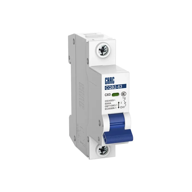
CHAC Electric offers the CQB2-63 6kA miniature circuit breaker for appropriately verified final-distribution duties. Its guidance on when 6kA is not enough reinforces the need to check point fault level. Where the study requires more capacity, review the CQB2-125 10kA MCB option and request the exact model documentation before specification.
Why is a higher breaking capacity not a complete specification?
The choice between a 6kA or 10kA MCB follows an engineering sequence: identify the prospective fault current at the installation point, confirm the standard and voltage, then check whether any tested back-up or cascading arrangement is permitted for the exact devices.
| Buyer question | Useful answer | Next verification |
|---|---|---|
| Is a 10kA MCB automatically better? | It provides a higher declared interrupting capacity under defined test conditions, but it does not fix an unsuitable curve, pole arrangement, coordination or enclosure. | Compare the complete product and installation requirements. |
| What does 10kA mean? | It is a short-circuit interruption rating, not the normal current carried by the circuit. | Read the exact standard, voltage and rating marking. |
| Can a 6kA device protect a 7kA point? | Not without a documented, permitted combination that establishes the required protection. | Obtain manufacturer back-up tables and the fault study. |
A defensible 10kA MCB decision still needs the same inputs as a 6kA selection: transformer impedance, source configuration, conductor length and impedance, parallel sources, voltage, poles, ambient conditions and the device standard. A headline number cannot replace a fault current calculation. For a product-family starting point, see the CQB2-63 MCB data and verify the exact ordered version before approval.
Why must both maximum and minimum fault current be checked?
Maximum fault current determines whether interruption duty is within the breaker’s declared capacity. Minimum fault current is a different design check: the current available through the relevant fault path must operate the protection within the required time. A long cable run can reduce the prospective current and ease the first check while making fast fault clearing more difficult. Selecting 10kA instead of 6kA does not resolve that second issue.
La società Schneider Electric fundamental circuit-breaker characteristics treats the instantaneous threshold and breaking rating separately. The designer should retain the time-current curve, relevant fault-path calculation and applicable disconnection requirement alongside the maximum fault study. Where residual-current protection forms part of the protective measure, verify that arrangement separately rather than treating breaking capacity as shock protection.
Also compare like quantities. A kA rating stated as rms short-circuit current is not interchangeable with a peak-current or let-through figure. Those values describe different aspects of the fault and tested protection arrangement. Do not convert a current-limiting upstream device’s graph into a permission to use any downstream MCB. Retain the exact tested combination and its voltage and rating limits.
The two checks should be reviewed together after source or circuit changes. A transformer replacement may increase maximum fault duty; a longer feeder may reduce the current available for fast operation. More rating headroom in one dimension cannot replace the other calculation.
Domande frequenti
Should I choose a 6kA or 10kA MCB?
Choose the rating that meets or exceeds the calculated prospective short-circuit current at the installation point under the applicable product standard. If the study is unavailable, do not use 6kA or 10kA as a guess.
What is the difference between a 10kA and 6kA breaker?
The declared short-circuit interruption capacity differs under defined test conditions. Neither number states the normal load current, conductor size, trip curve or suitability of the complete installation.
Is a 10kA MCB always better than a 6kA MCB?
No. It has higher interruption capability, but suitability also depends on voltage, current, curve, poles, standard, panel compatibility, and documentation. Select it when the fault study supports the choice.
Can I use a 6kA MCB if the prospective fault current is 7kA?
Not as a standalone device, because 7kA exceeds its rating. Use a suitably rated breaker or a manufacturer-verified combination covering the exact devices, voltage, and fault level.
Does a longer cable run reduce prospective short-circuit current?
Often yes, but length is only one input. Include conductor size and material, source impedance, parallel paths, and supply configuration in the calculation or measurement.
Can an upstream fuse make a 6kA MCB acceptable on a higher-fault system?
Only when the precise fuse-and-MCB combination has verified back-up data for the applicable fault level and voltage. Current limitation and let-through energy cannot be converted into a blanket permission to use any lower-rated downstream breaker.
How often should the fault-level assessment be reviewed?
Review it when the source, transformer, generator, bus tie, cable, or operating configuration changes, and at the interval required by the project’s electrical-safety program. Update labels and protective-device records where local rules require them.
Can a longer cable make a breaker easier to rate but slower to clear a fault?
Yes. Added impedance can reduce maximum prospective current while also reducing the current available to operate protection quickly. Check both interruption capacity and the required disconnection time using the actual fault path and device curve.
Referenze
- Schneider Electric: Caratteristiche fondamentali di un interruttore di circuito; instantaneous thresholds and Icn/Icu/Ics definitions, updated August 5, 2026.
- UL Solutions: Guida all’applicazione dei quadri elettrici di distribuzione; US panel and series-combination conditions, not automatic permission for IEC cascading.
- NFPA: NFPA 70 National Electrical Code; confirm local adoption and project requirements.
The reliable rule is simple: select the breaker from the fault current available where it will operate, not from habit or a catalogue number viewed in isolation.
For a project-specific review, share the single-line diagram, system voltage, calculated fault level, upstream protective device, required curve and poles, destination market, and documentation needs. Contact CHAC Electric to discuss the appropriate MCB configuration.