Wyłącznik magnetyczno-termiczny, który uruchamia się podczas rozruchu, może mieć nieodpowiednią charakterystykę natychmiastową, jednak zmiana jego krzywej bez uprzedniej kontroli obciążenia może zatuszować rzeczywistą awarię. Silnik, transformator lub zestaw sterowników LED charakteryzuje się określonym przebiegiem prądu w czasie, a nie tylko kategorią obciążenia. Wybrany urządzenie musi dopuszczać akceptowalne zachowanie podczas rozruchu, jednocześnie zapewniając ochronę przewodnika i prawidłowe wyłączanie zwarć w odpowiednim czasie. Niniejszy przewodnik porównuje krzywe B, C i D, wyjaśnia, jakie dane dotyczące prądów rozruchowych są istotne, oraz wskazuje niezbędne sprawdzenia, które zapobiegają osłabieniu projektu ochrony w wyniku zmiany krzywej.
Krótka odpowiedź brzmi: Praktyczna różnica polega na Krzywa B kontra krzywa C kontra krzywa D w wyłącznikach automatycznych Wybór to natychmiastowa strefa działania: powszechnie podawane zakresy 3–5 wartości znamionowej prądu dla B, 5–10 dla C i 10–20 dla D; należy zweryfikować dokładną krzywą urządzenia oraz podstawę testów. Wybierz na podstawie zmierzonego lub zgłoszonego przez producenta prądu rozruchowego obciążenia, a następnie zweryfikuj ochronę przewodów, potencjalny prąd zwarciowy i czas odłączenia., Zdolność przełaczania, koordynacja w łańcuchu dostaw oraz lokalne zasady projektowe. Wyższa krzywa nie jest uniwersalnym rozwiązaniem problemu nieuprawnionych wyłączników.
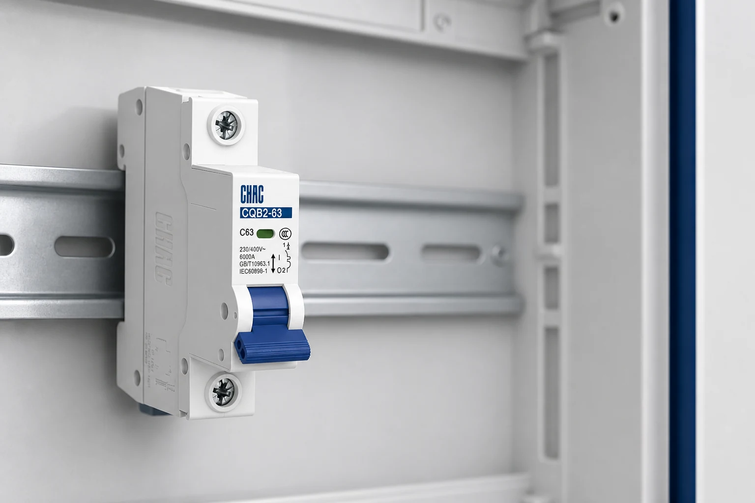
A wyłącznik nadprądowy Łączy zabezpieczenie termiczne przed przeciążeniem z szybkim, magnetycznym wyłączaniem w przypadku zwarć. Litera na krzywej określa głównie charakterystykę działania elektromagnesu; nie podaje ona wartości prądowej, zdolności przeładowej, napięcia, liczby biegunów ani statusu homologacji. Kupujący potrzebujący szerszego porównania mogą zapoznać się z tymi informacjami. Różnice między MCB a MCCB.
Co tak naprawdę zmieniają krzywe B, C i D?
Powszechnie publikowane natychmiastowe zakresy B, C i D to odpowiednio 3–5 × In, 5–10 × In i 10–20 × In, gdzie In to prąd znamionowy. Użyj dokumentowanego zakresu i pełnej krzywej oferowanego urządzenia, zamiast założenia, że każdy produkt przemysłowy stosuje te dokładne granice. Zatem, dla ilustracyjnego urządzenia 16 A, obszar magnetyczny wynosi 48–80 A dla B, 80–160 A dla C i 160–320 A dla D. Są to znormalizowane zakresy, a nie gwarancja, że każde urządzenie wyzwoli się dokładnie przy jednym prądzie.
Element termiczny reaguje na utrzymującą się przekrotną prąd. Zmiana z B16 na C16 nie tworzy obwodu z przewodem o wyższej wytrzymałości; zmienia ona tolerancję na krótkotrwały skok prądu przed uruchomieniem działania magnetycznego. Czas wyłączenia zależy również od prądu, początkowej temperatury, tolerancji oraz opublikowanej przez producenta krzywej. Zobacz tę wyjaśnioną na poziomie produktu Krzywe wyłączania B, C i D.
Jak porównują się krzywe B, C i D dla tej samej prądu znamionowego?
Jest to tabela kryterialna, a nie specyfikacja. Deklarowany standard urządzenia oraz opublikowana krzywa stanowią ramę referencyjną, jednak odpowiedniość zależy od obliczeń układu i danych producenta. Przykłady mają charakter poglądowy, ponieważ produkty w obrębie każdej kategorii mogą wykazywać bardzo różnorodne prądy rozruchowe. W przypadku porównania wyłączników typu B i typu C należy utrzymać stałą wartość prądu znamionowego i sprawdzić prąd rozruchowy oraz czas trwania rozruchu obciążenia na podstawie opublikowanych krzywych. Te rodzaje krzywych wyłączników nie wpływają na dopuszczalny prąd przewodnika.
| Charakterystyczny | Krzywa B | Krzywa C | Krzywa D |
|---|---|---|---|
| Często publikowany natychmiastowy pas | 3–5 × W | 5–10 × W | 10–20 × W |
| Tolerancja prądu wstępnego | Najniższy z trzech | Umierzone | Najwyższy z trzech |
| Warunkowy punkt wyjścia | Obwody końcowe oporowe lub o niskim prądzie rozruchowym | Zmieszane obciążenia o charakterze ogólnym lub urządzenia o umiarkowanym poborze prądu rozruchowego | Urządzenia o wysokim poborze prądu rozruchowego, potwierdzone obliczeniami |
| Wymóg prądu zwarciowego dla szybkiej pracy magnetycznej | Niższy | Wyższy | Najwyższy |
| Procurement risk if chosen by label alone | Nuisance trips on high inrush | May still be too sensitive or too slow for the actual circuit | Fault may not reach the magnetic band; coordination can be impaired |
| Tendencja do kosztów jednostkowych | Curve alone is rarely the useful cost comparator; documentation, ratings, approvals, downtime, and redesign exposure drive total cost. | ||
A curve that is too sensitive can interrupt normal operation. One that is too tolerant may miss the required automatic-disconnection time or disrupt selectivity. Unit-price savings rarely offset commissioning delay, repeated callouts, or a coordination gap.
How should load type and cold-start inrush guide selection?
Start with the current waveform, not the equipment category. Record steady current, inrush peak and duration, starts per hour, simultaneous energization, ambient temperature, and worst cold start. Under IEC 60364-4-43 principles, load current, protective-device rating, and conductor capacity must remain coordinated; changing curve never permits an undersized cable.
| Load or project condition | Dowody do zebrania | Conditional curve direction | Check before approval |
|---|---|---|---|
| Heating or simple resistive load | Nameplate current and switching duty | B may be suitable where inrush is low | Conductor capacity, ambient derating, disconnection time |
| Oświetlenie | Driver/ballast inrush and number switched together | B or C may fit; high LED-driver inrush can change the answer | Manufacturer limits, switching method, fault-loop result |
| Sockets and mixed general loads | Likely connected equipment and diversity | B or C depending on local practice and load behavior | Adopted code, cable, earth-fault path, residual-current requirements |
| Small motor or compressor | Locked-rotor/start current, acceleration time, starting method | C may work; D is considered only when higher inrush is proven | Motor overload protection, short-circuit coordination, start frequency |
| Transformer or bank of power supplies | Manufacturer inrush envelope at energization | C or D may be appropriate; phase angle and cold start matter | Primary conductors, upstream device, fault current, energization sequence |
If a breaker trips, distinguish normal inrush from overload, short circuit, earth leakage, overheating, loose connections, or a defective load. Moving from B to C or D without diagnosis can conceal the cause. This guide to a circuit breaker that keeps tripping explains the risk.
What standards and coordination checks govern the decision?
IEC 60898-1 covers circuit-breakers for overcurrent protection in household and similar installations for AC operation; its requirements and test methods underpin the familiar B, C, and D bands. IEC 60947-2 covers industrial circuit-breakers and uses a different application framework. A catalogue statement that a device was designed to a standard is not, by itself, third-party certification.
IEC 60364-4-43 addresses conductor overcurrent protection. The project also needs fault-loop or prospective-fault-current calculations and the applicable disconnection time. Because D needs more current than B to enter its magnetic band, a long run or higher loop impedance may make D unsuitable even if it stops start-up trips. Breaking capacity must independently meet the prospective short-circuit current.
Verify selectivity and backup protection with manufacturer tables or a time-current study. The market may apply IEC-based national rules, BS 7671, or another code; temperature, grouping, altitude, enclosure approval, residual-current protection, and equipment instructions can alter the answer. Unsupported claims can cause rejected submittals, rework, or shipment delays.
What should buyers verify before ordering a trip curve?
- Define voltage, frequency, poles, load current, cable, installation method, ambient conditions, and prospective fault current.
- Obtain the maker’s inrush curve or measure peak and duration under credible cold and simultaneous starts.
- Compare inrush with the full time-current envelope; calculate earth-fault clearing and short-circuit performance.
- Check conductor protection, breaking capacity, motor overload protection where relevant, selectivity, and enclosure compatibility.
- Confirm local code, exact-model documents, markings, certification requirements, and project approval before purchase.
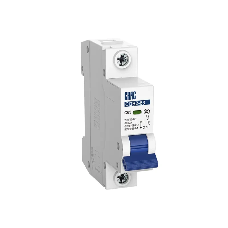
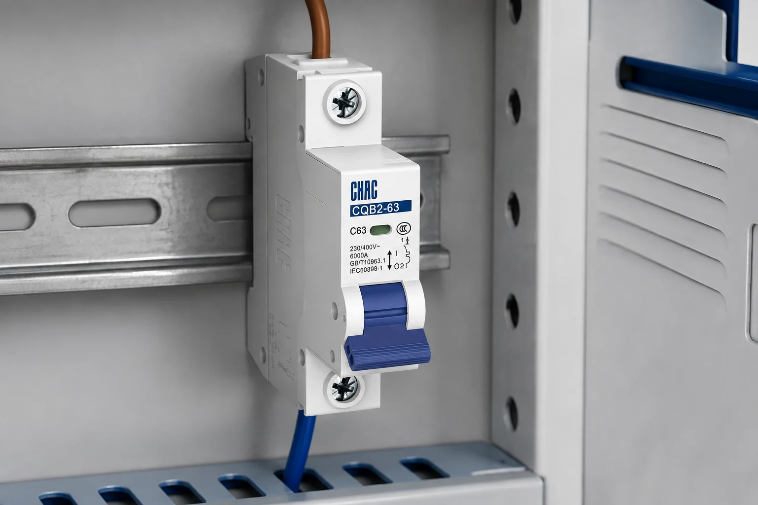
For CHAC Electric, the miniature circuit breaker selection review can use the CQB2-63 as a documented product-family reference. The only certification confirmed for this product in this article is CCC. IEC 60898-1 is a standard and test framework, not a certification; buyers should request evidence for the exact model, rating, curve, and destination-market requirement rather than infer approval from a standard number.
Why can a curve change leave the underlying fault unresolved?
A C curve vs D curve MCB decision is conditional: the instantaneous band must tolerate the documented inrush while the thermal element, conductor protection, prospective fault current and disconnection requirements remain suitable. A curve change is not a substitute for checking a motor, transformer, power supply or wiring fault.
| Pytanie | Evidence-led answer | Check before changing curve |
|---|---|---|
| Is C curve better than D curve? | Neither is universally better; C and D are selected for different inrush conditions within the device and installation limits. | Load data, inrush waveform or manufacturer starting information. |
| Can a higher curve stop nuisance trips? | It may change instantaneous operation, but a loose connection, undersized conductor or failing load still requires diagnosis. | Terminal condition, conductor calculation and fault checks. |
| Does D curve mean a motor always needs it? | No. Motor duty, starting method, locked-rotor current, number of starts and coordination determine the choice. | Motor data and the complete protection scheme. |
Record MCB inrush current at the point where the protection is selected, and distinguish it from steady-state load current. A short, high motor starting current may be normal, but repeated starts, a jammed rotor, low control voltage or a deteriorating capacitor can produce a different symptom. The CQB2-63 curve guidance linked above can support a shortlist; the exact trip curve and installation conditions must still be confirmed from the ordered model documents.
Why does inrush duration matter as much as the peak?
A peak-current number without duration is an incomplete input. A brief capacitor-charging surge and a motor that takes longer to accelerate can present different operating duties even if their recorded peaks are similar. Compare the manufacturer’s starting envelope or suitable measurements with the full time-current curve, including tolerances. An ordinary meter that misses a short surge cannot establish that no inrush occurred.
For lighting or multiple power supplies, record how many units are energized together and whether cold start or automatic restoration changes that number. Staggering starts may be a design option when the equipment and controls support it, but it is not a substitute for identifying a stalled load, insulation fault or loose termination. Do not increase the ampere rating merely to tolerate a surge.
Schneider Electric circuit-breaker characteristics guide shows both familiar domestic curve bands and different examples for modular industrial devices. That is why the curve letter must be tied to the exact product. A higher instantaneous threshold also needs sufficient current in the relevant fault path to meet the required clearing time. Confirm that limit before changing B to C or C to D, particularly on long runs or sources with limited fault contribution.
What should be recorded before a trip curve is changed?
For a proposed Krzywa ruchu MCB change, keep the original device identification, the reason for the change and the approved replacement specification together. Record the observed startup condition, including which loads start together and whether the supply mode changes. “Trips occasionally” gives a designer less useful information than a repeatable description of the event.
Ask the designer which assumptions remain valid under generator supply, a long feeder or a changed load group. Then attach the revised fault and disconnection assessment to the change record. Do not use a nuisance-trip improvement alone as proof that the new curve protects the circuit adequately.
The short-circuit current and breaking-capacity guide explains the separate maximum-fault check. Keeping that check beside the curve assessment prevents the replacement from being approved on starting behavior alone.
Często zadawane pytania
What is the difference between C curve and D curve MCBs?
Ich natychmiastowe pasma operacyjne są różne, dlatego dopuszczalny prąd włączeniowy oraz wymagany margines dla prądu zwarciowego również się różnią. Wybór należy dokonać na podstawie danych dotyczących obciążenia i kompleksowego projektu zabezpieczeń, a nie ze względu na preferencję wyższej litery.
Dlaczego wyłącznik automatyczny odbija podczas uruchamiania urządzenia?
Prąd wstępnego poboru może przekraczać wybrany zakres działania zabezpieczenia natychmiastowego, jednak identyczne objawy mogą wystąpić również w przypadku awarii, niskiego napięcia zasilania, zablokowanego silnika lub luźnego połączenia. Przed zmianą charakterystyki należy dokonać pomiarów i zdiagnozować obciążenie.
Which is better, a B curve or C curve MCB?
Neither is universally better. B reaches its magnetic operating region at a lower multiple of rated current, while C tolerates more inrush; the correct choice is the one that passes load-starting, cable-protection, fault-clearing, and local-code checks.
Can I replace a B curve MCB with a C curve of the same amp rating?
Not from the amp rating alone. Confirm the load inrush, earth-fault loop or prospective fault current, disconnection time, breaking capacity, conductor protection, panel compatibility, and approval requirements before substituting.
Is a D curve MCB always required for motors?
No. Motor start current and duration vary with motor design, load torque, starter, voltage, and temperature; some circuits coordinate with C, while a documented high-inrush case may justify D. Motor overload protection and short-circuit coordination must also be checked.
Why does an MCB trip when equipment starts in cold weather?
Cold conditions can change lubricant drag, compressor pressure behavior, motor acceleration, transformer magnetizing inrush, or power-supply charging. Measure or obtain the worst-case inrush envelope and inspect for actual faults before changing curve or rating.
Does a higher trip curve increase breaking capacity?
No. B, C, and D describe instantaneous trip-current bands; breaking capacity is a separate rated short-circuit performance. Both must be suitable for the circuit, and neither replaces a coordination study.
Is an inrush peak alone enough to select an MCB curve?
No. Duration, repeated or simultaneous starts and the full device curve also matter. Use equipment starting data or suitable measurements, then verify conductor protection, fault clearing and breaking capacity.
Do all industrial breakers with a D label share one operating band?
No universal assumption should be made. Published industrial characteristics and test frameworks can differ. Read the exact device curve and declared standard before applying a familiar B/C/D screening range.
Przypisy
- Schneider Electric: Fundamental characteristics of a circuit-breaker; published domestic and industrial curve examples; exact manufacturer curves govern.
- IET: BS 7671 Requirements for Electrical Installations; applicable national edition and circuit design must be verified.
- Schneider Electric: Funkcje ochrony silników; motor-protection duties extend beyond an MCB curve.
The durable rule is simple: select the curve from verified load behavior, then prove that the whole protective system still clears faults safely.
Review the CQB2-63 documentation against your single-line diagram and project requirements, then skontaktuj się z CHAC Electric with the load profile, conductor details, fault-current calculation, destination market, and required compliance evidence for a focused selection discussion.