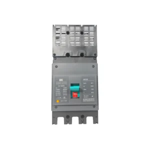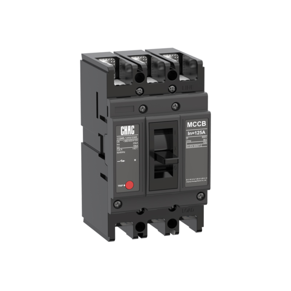
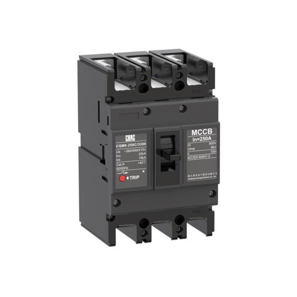
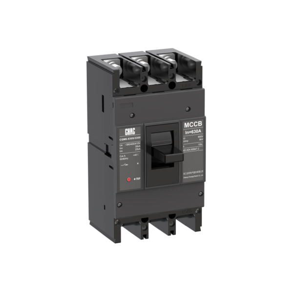
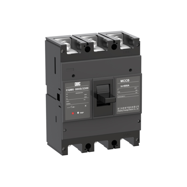
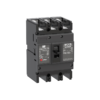
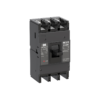
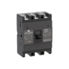
CQM6 Standardowy złącze obrotowe w obudowie (MCCB) Producent OEM
The CQM6 Wyłącznik miękki Zapewnia zabezpieczenie przeciążeniowe i przed zwarciem w zakresie 16–1600A, który został opublikowany. Specyfikacja powinna uwzględniać napięcie systemu, obciążenie, koordynację przewodów, spodziewany prąd zwarciowy oraz obowiązujące przepisy – a nie tylko wartość amperową.
Oversight produktu
CQM6 to wyłącznik obwodowy MCCB przeznaczony do aplikacji dystrybucyjnych i ochronnych w sieciach prądu przemiennego. Jego oficjalny zakres obejmuje 16–1600A z opcjami 2P / 3P / 4P, w zależności od obudowy; CQM6-1600: opcje 3P. Wybór zależy od kompletnego projektu systemu energetycznego, w tym poziomu zwarciowego, koordynacji, przepustowości przewodów, warunków obudowy oraz lokalnych przepisów.
Podana specyfikacja produktu odwołuje się do IEC/EN 60947-1, IEC/EN 60947-2, IEC/EN 60947-3 i IEC/EN 60947-4, a także do GB/T 14048.1, .2, .3 i .4. Same w sobie te odniesienia normowe nie stanowią podstawy do certyfikacji dla konkretnego zamówienia.
Kluczowe cechy
Typowe zastosowania
Typowe zastosowania obejmują sieci dystrybucyjne w sektorze komercyjnym, przemysłowym oraz infrastrukturalnym, a także obwody silnikowe. Są to konteksty oceny, a nie uniwersalne zatwierdzenia. Przed ustaleniem specyfikacji należy potwierdzić dokładny rozmiar obudowy, napięcie, zdolność wyłączania, jednostkę odbiorczą, akcesoria oraz sposób montażu.
Wnioski i przewodnik po procesie rekrutacji
Użyj poniższych zweryfikowanych wartości CQM6, aby stworzyć krótką listę, a następnie zweryfikuj cały obwód. Wartość znamionowa wyłącznika MCCB nie zastępuje obliczeń przewodów, analizy prądu zwarciowego, przeglądu koordynacji ani lokalnych wymagań instalacyjnych.
| Punkt wyboru | Odniesienie CQM6 | Co projekt musi potwierdzić |
|---|---|---|
| Prąd znamionowy | 16–1600A | Projekt prądu, przewodność przewodu, sposób instalacji, temperatura i grupowanie |
| Napięcie | AC 400/415V; CQM6-1600 również wymienia konfiguracje 660/690V | System dostaw i klasyfikacja urządzeń |
| Polacy | 2P / 3P / 4P, w zależności od ramy; CQM6-1600: 3P | Traktowanie przewodów pod napięciem i przewodu neutralnego |
| Podróż / ochrona | thermal-magnetic trip | Profil obciążenia, reakcja na awarię i koordynacja |
| Przerwanie przepustowości | Klasy C/S/M/H/L, z Icu do 100kA dla wymienionych konfiguracji CQM6-1600 660/690V; sprawdź dokładny typ obudowy i napięcie. | Przewidywany prąd zwarciowy w punkcie instalacji |
Ochrona stała vs regulowana
Urządzenie termomagnetyczne o stałej charakterystyce może być odpowiednie dla stabilnej konstrukcji, podczas gdy regulowana jednostka wyłączająca może ułatwić koordynację w przypadku, gdy analiza projektowa wymaga dostosowania ustawień na miejscu.
Koordynacja wyjazdu
Porównaj opcje wyłączników niskonapięciowych →
MCCB kontra MCB
Zwykle wyłącznik magnetyczno-termostatyczny (MCCB) jest wybierany ze względu na większy prąd znamionowy, zdolność przeładowczą lub większą elastyczność w zakresie akcesoriów; natomiast wyłącznik termomagnetyczny (MCB) może być bardziej odpowiedni do kompaktowych obwodów końcowych.
Obciążenie znamionowe i awaryjne
Porównaj wyłącznik obwodowy wielokrotnego użytku (MCCB) i wyłącznik obwodowy jednorazowego użytku (MCB) →
Icu kontra Ics
The saved data for CQM6 lists C/S/M/H/L classes, with Icu up to 100kA for the listed CQM6-1600 660/690V configurations; verify the exact frame and voltage. Match the declared duty to the prospective short-circuit current and continuity objective.
Studium zwarć
Przegląd Działu Obsługi Technicznej →
Układ biegunów i przewodu neutralnego
Published pole options are 2P / 3P / 4P, depending on frame; CQM6-1600: 3P. Confirm which conductors must be switched, protected and isolated together.
Układ systemu
View MCCB Range →
Przewodnik po zamówieniach
- State the exact model: CQM6.
- Provide frame and rated current within the published range: 16–1600A.
- Confirm poles: 2P / 3P / 4P, depending on frame; CQM6-1600: 3P.
- Specify the trip unit or protection function: thermal-magnetic trip.
- Provide system voltage, frequency, application, expected fault level, destination market and quantity.
- List required accessories, terminals, documents and any approved OEM/ODM marking or packaging requirements.
Kontrole instalacji i koordynacji
- Use the exact model drawing and instructions; do not infer terminal positions, supply direction or accessory compatibility from another MCCB.
- Verify conductor material and cross-section against the circuit calculation, terminal data, temperature and grouping.
- Confirm Icu/Ics or DC fault duty, upstream/downstream coordination, enclosure conditions, altitude and clearances.
- Installation, isolation, testing and maintenance must be performed by qualified personnel under applicable rules.
Selection Guide

| Product code ① | Extension Code ② | Shell frame grade ③ | Breaking capacity ④ | Operating method ⑤ | Number of poles ⑥ | |||||
|---|---|---|---|---|---|---|---|---|---|---|
| CQM6 | G | 125 | C | P | 4 | |||||
| Przełącznik obwodowy w obudowie formowanej | —:Thermal and magnetic protection are not adjustable G:Overload alarm without trip function |
C | S | L | M | H | P:Motorized operation Z:Turning handle W.Direct operation |
125A:2P,3P,4P 160A:3P,4P 250A:2P,3P,4P 400A:3P,4P 630A:3P,4P 800A:3P,4P 1250A:3P,4P 1600A:3P |
||
| 125 | 125 | 15/8 | 25/18 | / | / | / | ||||
| 160 | 160 | 25/18 | 35/25 | / | 50/35 | / | ||||
| 250 | 250 | 25/18 | 35/25 | / | 50/35 | / | ||||
| 400 | 400 | / | 35/25 | / | 50/35 | 70/50 | ||||
| 630 | 630 | / | 35/25 | / | 50/35 | 70/50 | ||||
| 800 | 800 | / | 35/25 | / | 50/35 | 70/50 | ||||
| 1250 | 1250 | / | / | / | 50/35 | 70/55 | ||||
| 1600 | 1600 | / | / | 70/20 | 100/35 | 100/50 | ||||
| Trip Unit &Accessories ⑦ | Rated current A ⑧ | Function ⑨ | 4P Option Code ⑩ | Special code ⑪ | |
|---|---|---|---|---|---|
| 300 | 125A | 2 | A | I | |
| The first digit indicates the type of detent 2:instantaneous detent only 3:Duplicate detent Note:The last two digits are the accessory designator(see accessory table). |
125 | 16,20,32,40,50,63,80,100,125 | 1:For power distribution 2:For motor protection |
A:N-pole is unprotected and cannot be combined B:N-pole is unprotected and can be combined C:N-pole is protected and can be combined D:N-pole is protected and cannot be combined |
I:Overload alarm non trip function |
| 160 | 16,20,32,40,50,63,80,100,125,140,160 | ||||
| 250 | 100,125,140,160,180,200,225,250 | ||||
| 400 | 250,315,350,400 | ||||
| 630 | 250,315,350,400,500,630 | ||||
| 800 | 500,630,700,800 | ||||
| 1250 | 800,1000,1250 | ||||
| 1600 | 800,1000,1250,1400,1500,1600 | ||||
| Accessory Voltage ⑫ | Motorized operating voltage ⑬ | Installation ⑭ | Terminal Block Option ⑮ | |||
|---|---|---|---|---|---|---|
| Q1 | D1 | Q | 2 | |||
| Undervoltage detent Q1:AC220V Q2:AC240V Q3:AC380V Q4:AC415V | Shunt release F1:AC220V F2:AC380V F3:DC110V F4:DC24V | Auxiliary alarm J1:AC125V J2:AC250V J3:DC125V J4:DC24V | CD1 Electrical Operation D1:AC220V D2:AC230V D3:AC380V D4:AC400V |
CD2 Obsługa elektryczna D5:AC230V D6:AC110V D7:DC220 D8:DC110 D9:AC110–240V D10:DC100–220V | Q:Front of plate H:Rear of plate C:Inserted | 1:Noinstitution 2:Installation |
| Note:When motorized operation is selected,please refer to the external accessories for the two voltages applicable for motorized operation. | ||||||
Accessory List
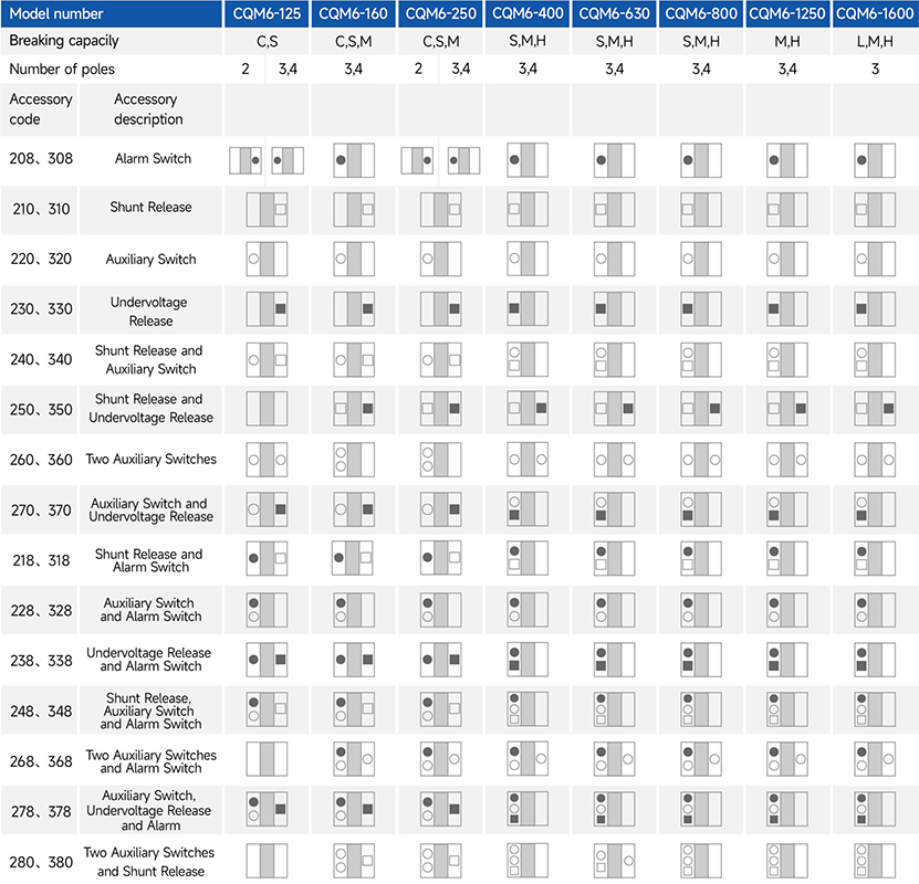
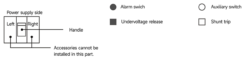
CHAC offers a right-side auxiliary switch, a left-side shunt release and a left-side undervoltage release.
For accessory codes 220, 320, 240, 340, 270 and 370, the auxiliary switch can provide two contact pairs. Specify this requirement when ordering.
For accessory codes 250 and 350, the shunt release and undervoltage release on frames 400 and above are available only for 3-pole circuit breakers.
Main Technical Parameters
| Model number | CQM6-125 | CQM6-160 | |||||
|---|---|---|---|---|---|---|---|
| Rated current of frame level Inm(A) | 125 | 160 | |||||
| Liczba biegunów | 2,3,4 | 3,4 | |||||
| Rated current In(A),at 40°C,50°C,55°C | 16,20,25,32,40,50,63,80,100,125 | 16,20,25,32,40,50,63,80,100,125,140,160 | |||||
| Rated operating voltage Ue(V),AC 50/60Hz | 400/415 | 400/415 | |||||
| Nominalne napięcie izolacji Ui (V) | 800 | 800 | |||||
| Rated impulse withstand voltage Uimp(KV) | 8 | 8 | |||||
| Breaking capacity designation | C | S | C | S | M | ||
| Short-circuit breaking capacity Icu/Ics(kA) | AC400/415V | 15/8 | 25/18 | 25/18 | 35/25 | 50/35 | |
| Selectivity category | A | A | A | A | A | ||
| Number of operating cycles(cycle) | ON | 6000 | 6000 | ||||
| OFF | 10000 | 10000 | |||||
| Trip mechanisms and protection types | Magnetic trip | Power distribution protection | ● | ● | ● | ● | ● |
| Motor protection | ● | ● | ● | ● | ● | ||
| Thermal-magnetic trip | Power distribution protection | ● | ● | ● | ● | ● | |
| Motor protection | ● | ● | ● | ● | ● | ||
| Akcesorium | Auxiliary contacts | ● | ● | ● | ● | ● | |
| Alarm contacts | ● | ● | ● | ● | ● | ||
| Shunt disconnect | ● | ● | ● | ● | ● | ||
| Undervoltage detent | ● | ● | ● | ● | ● | ||
| Manual operating mechanism | ● | ● | ● | ● | ● | ||
| Motorized operating mechanism | ● | ● | ● | ● | ● | ||
| Backplane wiring | ● | ● | ● | ● | ● | ||
| Inserted | ● | ● | ● | ● | ● | ||
| Coupling plate | ● | ● | ● | ● | ● | ||
| Partition between phases | ● | ● | ● | ● | ● | ||
| Derivative products | Dedicated for prepayment electric meters | ● | ● | ● | ● | ● | |
| Overload alarm without trip | – | – | ● | ● | ● | ||
| Overall dimensions (mm) (a–b–c–ca) | 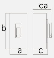 |
3 P | 75×130×68×91 | 90×155×70×95 | 90×155×85 ×109 | ||
| 4 P | 100×130×68×91 | 120×155×70×95 | 120×155×85 ×109 | ||||
Note: ● indicates an available optional accessory; – indicates that the accessory is not available.
Main Technical Parameters
| Model number | CQM6-250 | CQM6-400 | CQM6-630 | ||||||||
|---|---|---|---|---|---|---|---|---|---|---|---|
| Rated current of frame level Inm(A) | 250 | 400 | 630 | ||||||||
| Liczba biegunów | 2,3,4 | 3,4 | 3,4 | ||||||||
| Rated current In(A),at 40°C,50°C,55°C | 100,125,140,160,180,200,225,250 | 250,315,350,400 | 250,315,350,400,500,630 | ||||||||
| Rated operating voltage Ue(V),AC 50/60Hz | 400/415 | 400/415 | 400/415 | ||||||||
| Nominalne napięcie izolacji Ui (V) | 800 | 800 | 800 | ||||||||
| Rated impulse withstand voltage Uimp(KV) | 8 | 8 | 8 | ||||||||
| Breaking capacity designation | C | S | M | S | M | H | S | M | H | ||
| Short-circuit breaking capacity Icu/Ics(kA) | AC400/415V | 25/18 | 35/25 | 50/35 | 35/25 | 50/35 | 70/50 | 35/25 | 50/35 | 70/50 | |
| Selectivity category | A | A | A | A | A | A | A | A | A | ||
| Number of operating cycles (cycle) |
ON | 6000 | 3000 | 3000 | |||||||
| OFF | 10000 | 8000 | 8000 | ||||||||
| Trip mechanisms and protection types | Magnetic trip | Power distribution protection | ● | ● | ● | ● | ● | ● | ● | ● | ● |
| Motor protection | ● | ● | ● | ● | ● | ● | ● | ● | ● | ||
| Thermal-magnetic trip | Power distribution protection | ● | ● | ● | ● | ● | ● | ● | ● | ● | |
| Motor protection | ● | ● | ● | ● | ● | ● | ● | ● | ● | ||
| Akcesorium | Auxiliary contacts | ● | ● | ● | ● | ● | ● | ● | ● | ● | |
| Alarm contacts | ● | ● | ● | ● | ● | ● | ● | ● | ● | ||
| Shunt disconnect | ● | ● | ● | ● | ● | ● | ● | ● | ● | ||
| Undervoltage detent | ● | ● | ● | ● | ● | ● | ● | ● | ● | ||
| Manual operating mechanism | ● | ● | ● | ● | ● | ● | ● | ● | ● | ||
| Motorized operating mechanism | ● | ● | ● | ● | ● | ● | ● | ● | ● | ||
| Backplane wiring | ● | ● | ● | ● | ● | ● | ● | ● | ● | ||
| Inserted | ● | ● | ● | ● | ● | ● | ● | ● | ● | ||
| Coupling plate | ● | ● | ● | ● | ● | ● | ● | ● | ● | ||
| Partition between phases | ● | ● | ● | ● | ● | ● | ● | ● | ● | ||
| Derivative products | Dedicated for prepayment electric meters | ● | ● | ● | ● | ● | ● | ● | ● | ● | |
| Overload alarm without trip | ● | ● | ● | ● | ● | ● | ● | ● | ● | ||
| Overall dimensions (mm) (a-b-c-ca) | |
3 P | 105×165×70×95 | 105×165×93×118 | 140×257×107×156 | 140×257×107×156 | |||||
| 4 P | 140×165×70×95 | 140×165×93×118 | 185×257×107×156 | 185×257×107×156 | |||||||
Note: ● indicates an available optional accessory; – indicates that the accessory is not available.
Main Technical Parameters
| Model number | CQM6-800 | CQM6-1250 | CQM6-1600 | |||||||
|---|---|---|---|---|---|---|---|---|---|---|
| Rated current of frame level Inm(A) | 800 | 1250 | 1600 | |||||||
| Liczba biegunów | 3,4 | 3,4 | 3 | |||||||
| Rated current In(A),at 40°C,50°C,55°C | 500,630,700,800 | 800,1000,1250 | 800,1000,1250,1400,1500,1600 | |||||||
| Rated operating voltage Ue(V),AC 50/60Hz | 400/415 | 400/415 | 400/415V | 660/690V | ||||||
| Nominalne napięcie izolacji Ui (V) | 800 | 1000 | 1000 | |||||||
| Rated impulse withstand voltage Uimp(KV) | 8 | 12 | 12 | |||||||
| Breaking capacity designation | S | M | H | M | H | L | M | H | ||
| Short-circuit breaking capacity Icu/Ics(kA) | AC400/415V | 35/25 | 50/35 | 70/50 | 50/35 | 70/55 | 70/20 | 100/35 | 100/50 | |
| Selectivity category | A | A | A | A | A | A | A | A | ||
| Number of operating cycles (cycle) |
ON | 1000 | 1000 | 500 | ||||||
| OFF | 3000 | 3000 | 3000 | |||||||
| Trip mechanisms and protection types | Magnetic trip | Power distribution protection | ● | ● | ● | ● | ● | ● | ● | ● |
| Motor protection | ● | ● | ● | ● | ● | ● | ● | ● | ||
| Thermal-magnetic trip | Power distribution protection | ● | ● | ● | ● | ● | ● | ● | ● | |
| Motor protection | ● | ● | ● | ● | ● | ● | ● | ● | ||
| Akcesorium | Auxiliary contacts | ● | ● | ● | ● | ● | ● | ● | ● | |
| Alarm contacts | ● | ● | ● | ● | ● | ● | ● | ● | ||
| Shunt disconnect | ● | ● | ● | ● | ● | ● | ● | ● | ||
| Undervoltage detent | ● | ● | ● | ● | ● | ● | ● | ● | ||
| Manual operating mechanism | ● | ● | ● | ● | ● | ● | ● | ● | ||
| Motorized operating mechanism | ● | ● | ● | ● | ● | ● | ● | ● | ||
| Backplane wiring | ● | ● | ● | ● | ● | ● | ● | ● | ||
| Inserted | ● | ● | ● | ● | ● | ● | ● | ● | ||
| Coupling plate | ● | ● | ● | ● | ● | ● | ● | ● | ||
| Partition between phases | ● | ● | ● | ● | ● | ● | ● | ● | ||
| Derivative products | Dedicated for prepayment electric meters | ● | ● | ● | ● | ● | ● | ● | ● | |
| Overload alarm without trip | ● | ● | ● | ● | ● | ● | ● | ● | ||
| Overall dimensions (mm) (a–b–c–ca) | |
3 P | 210×275×113×162 | 210×275×113×162 | 210×268×161×240 | |||||
| 4 P | 280×275×113×162 | 280×275×113×162 | ||||||||
Note: ● indicates an available optional accessory; – indicates that the accessory is not available.
Operating Characteristics
The following table gives the inverse-time operating characteristics for distribution protection with all poles energised at an ambient temperature of +40°C, without humidity compensation.
| Test current designation | Setting current multiple | Conventional time | Initial state |
|---|---|---|---|
| In≤63 63<In | |||
| Conventional non-tripping current | 1.05 | ≥1h ≥2h | Cool state |
| Conventional tripping current | 1.30 | <1h <2h | Hot state |
The following table gives the inverse-time operating characteristics for motor protection with all poles energised at an ambient temperature of +40°C, without humidity compensation.
| Test current designation | Setting current multiple | Conventional time | Initial state |
|---|---|---|---|
| In≤800 | |||
| Conventional non-tripping current | 1.0 | ≥2h | Cool state |
| Conventional tripping current | 1.2 | <2h | Hot state |
The operating-characteristics reference gives an instantaneous trip current setting of 10In for distribution protection. Confirm the applicable trip-unit setting for the ordered configuration.
The operating-characteristics reference gives an instantaneous trip current setting of 12In for motor protection.
The stated accuracy of the instantaneous trip current setting is 20% of the setting value.
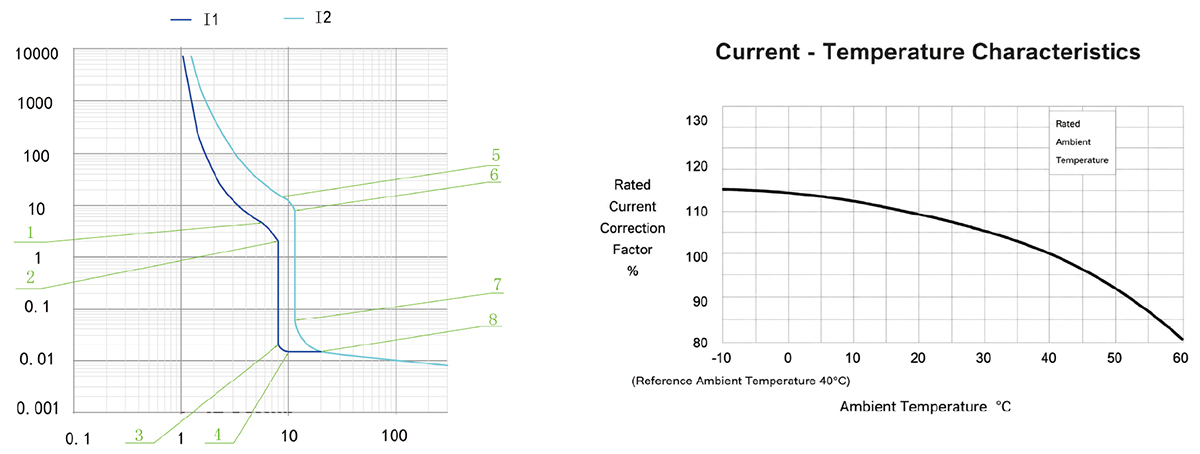
CQM6-125 Operating Characteristic Curve
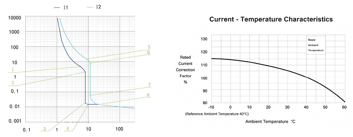
CQM6-160 Operating Characteristic Curve
CQM6-250 Operating Characteristic Curve
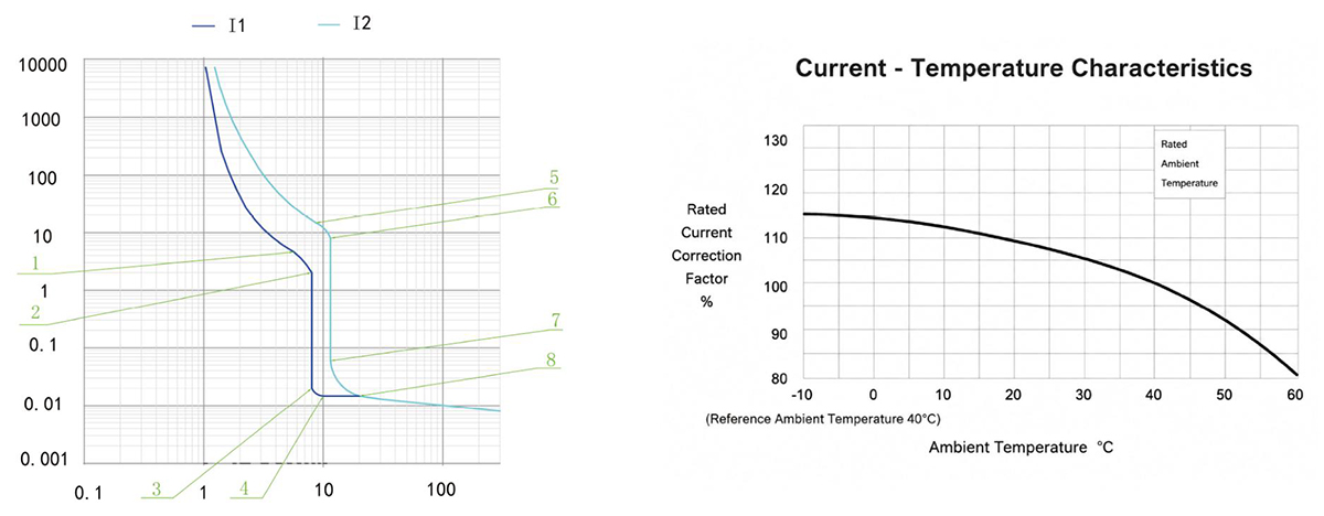
CQM6-400 / 630 Operating Characteristic Curve
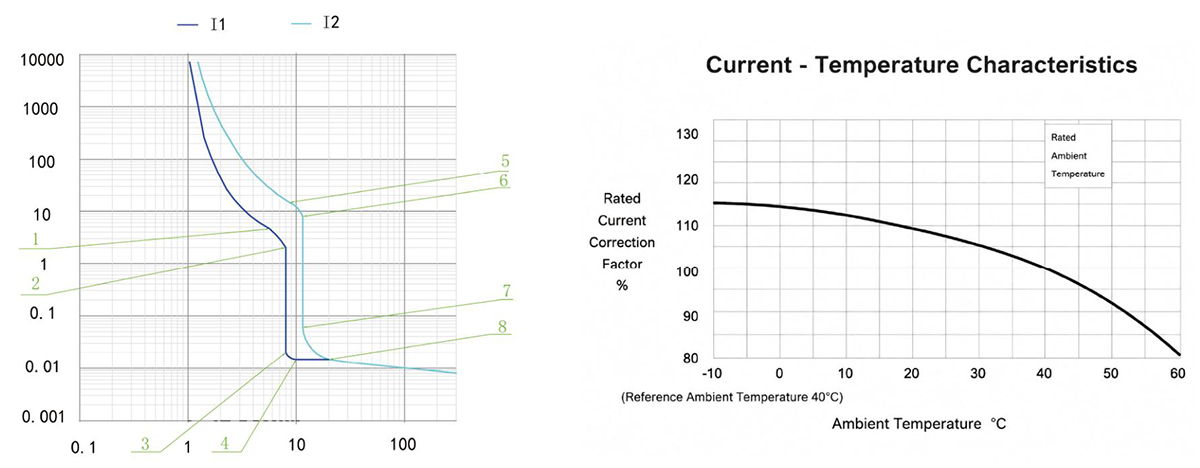
CQM6-800 Operating Characteristic Curve
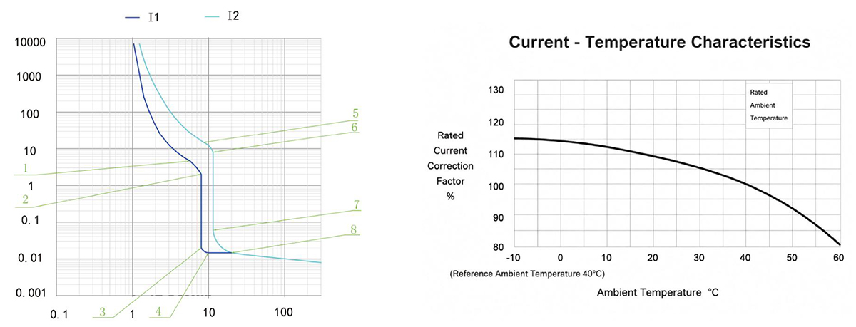
CQM6-1250 Operating Characteristic Curve
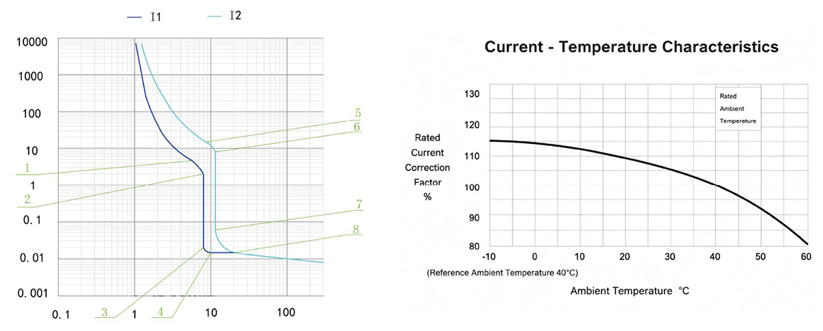
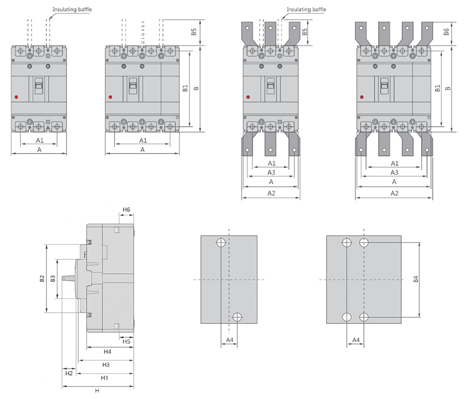
CQM6-125~1250 Outline and Installation Dimensions(mm)
CQM6-1600 Outline and Installation Dimensions(mm)
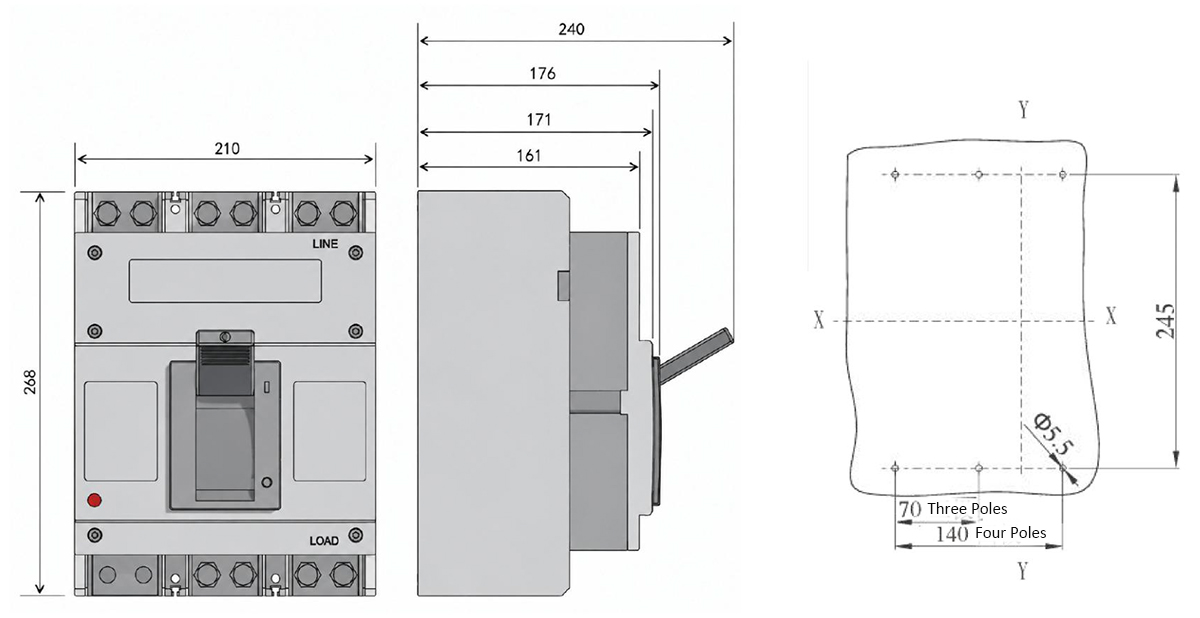
| Przełącznik obwodowy w obudowie formowanej | Overall dimension | Installation dimensions | Boit | |||||||||||||||||||||
|---|---|---|---|---|---|---|---|---|---|---|---|---|---|---|---|---|---|---|---|---|---|---|---|---|
| A | A1 | A2 | A3 | B | B1 | B2 | B3 | B5 | B6 | H | H1 | H2 | H3 | H4 | H5 | H6 | A4 | B4 | ||||||
| 3P | 4P | 3P | 4P | 3P | 4P | 3P | 4P | |||||||||||||||||
| CQM6-125CSM | 75 | 100 | 50 | 75 | – | – | – | – | 130 | 114 | 85 | 50 | 48 | – | 91 | 73.4 | 2.4 | 68 | 61 | 23.9 | 24 | 25 | 111 | M6 |
| CQM6-160CS | 90 | 120 | 60 | 90 | – | – | – | – | 155 | 134 | 103 | 50 | 48 | – | 95 | 75.5 | 2.1 | 70 | 62 | 24 | 24.8 | 30 | 132 | M8 |
| CQM6-160M | 90 | 120 | 60 | 90 | – | – | – | – | 155 | 134 | 103 | 50 | 48 | – | 109.5 | 90 | 2.1 | 85 | 76.5 | 23.6 | 25 | 30 | 132 | M8 |
| CQM6-250CS | 105 | 140 | 70 | 105 | – | – | – | – | 165 | 144 | 102 | 50 | 97 | – | 95 | 74.2 | 2.7 | 70 | 61.4 | 22.3 | 23.1 | 35 | 126 | M8 |
| CQM6-250M | 105 | 140 | 70 | 105 | – | – | – | – | 165 | 144 | 102 | 50 | 95 | – | 118.5 | 97.7 | 2.7 | 93.4 | 84.8 | 22.9 | 23.3 | 35 | 126 | M8 |
| CQM6-400SMH | 140 | 185 | 70 | 132 | 140 | 196 | 112 | 168 | 257 | 230 | 179 | 90 | 103 | 42 | 156 | 111.7 | 3.5 | 107.5 | 99.5 | 30.9 | 32.4 | 44 | 194 | M10 |
| CQM6-630SMH 400A | 140 | 185 | 88 | 132 | 140 | 196 | 112 | 168 | 257 | 230 | 179 | 90 | 103 | 42 | 156 | 111.7 | 3.5 | 107.5 | 99.5 | 30.9 | 32.4 | 44 | 194 | M10 |
| CQM6-630SMH 630A | 140 | 185 | 88 | 132 | 140 | 196 | 112 | 168 | 257 | 230 | 179 | 90 | 103 | 42 | 156 | 111.7 | 3.5 | 107.5 | 99.5 | 33.2 | 34 | 44 | 194 | M10 |
| CQM6-800SMH 630A | 210 | 280 | 140 | 210 | 180 | 250 | 140 | 210 | 275 | 243 | 192 | 90 | 103 | 87 | 162.5 | 118 | 2.7 | 113.4 | 105.5 | 28.3 | 30.4 | 70 | 242.5 | M12 |
| CQM6-800SMH 800A | 210 | 280 | 140 | 210 | 180 | 250 | 140 | 210 | 275 | 243 | 192 | 90 | 103 | 87 | 162.5 | 118 | 2.7 | 113.4 | 105.5 | 29 | 32.6 | 70 | 242.5 | M12 |
| CQM6-1250SMH | 210 | 280 | 140 | 210 | 180 | 250 | 140 | 210 | 275 | 243 | 192 | 90 | 103 | 87 | 162.5 | 118 | 2.7 | 113.4 | 105.5 | 31.3 | 34.4 | 70 | 242.5 | M10 |
| CQM6-1600LMH | 210 | – | 140 | – | – | – | – | – | 268 | 240 | 118 | 97 | 110 | – | 240 | 171 | 5 | 161 | 150 | 33 | 34 | 70 | 245.0 | M10 |
Dlaczego wybrać CHAC
Dzięki ponad 30 latom doświadczenia w produkcji, ponad 1100 pracownikom i ponad 100M słupom
Roczna wydajność i 90% automatyzacji produkcji pozwalają CHAC na stabilną zdolność produkcyjną oraz ścisłe
kontrola jakości dla globalnych klientów OEM/ODM. Nasz wewnętrzny system produkcyjny wspiera długoterminowe
współpraca z markami elektrycznymi, importerami i dystrybutorami.

30+
ROKIĘLNE DOŚWIADCZENIE
Specjalizujemy się w produkcji urządzeń elektrycznych niskiego napięcia

1100+
ZAPOSOBOWANI
Profesjonalny zespół zapewnia stabilną jakość i terminowość dostaw

100 milionów+
ROZDZIELANIE NAPĘDU ROZNOMÓWCOW WROCŁAWA
Duża zdolność produkcyjna umożliwiająca zaspokojenie globalnego popytu

90%
AUTOMATYCZNA PRODUKCJA
Zaawansowana automatyzacja dla wysokiej wydajności i spójności
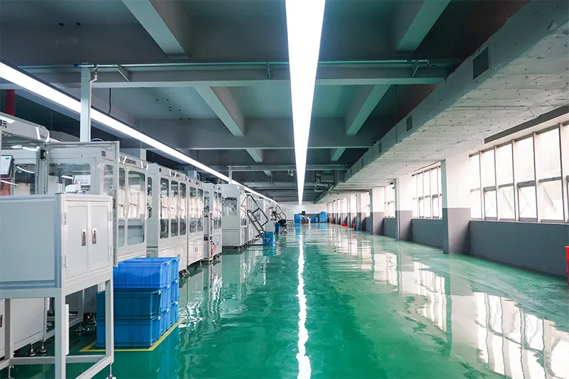
Automatyczna linia montażowa

Laboratorium Badawcze
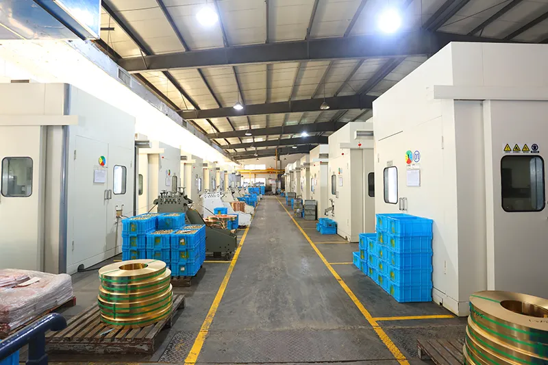
Wtrysk i tłoczenie
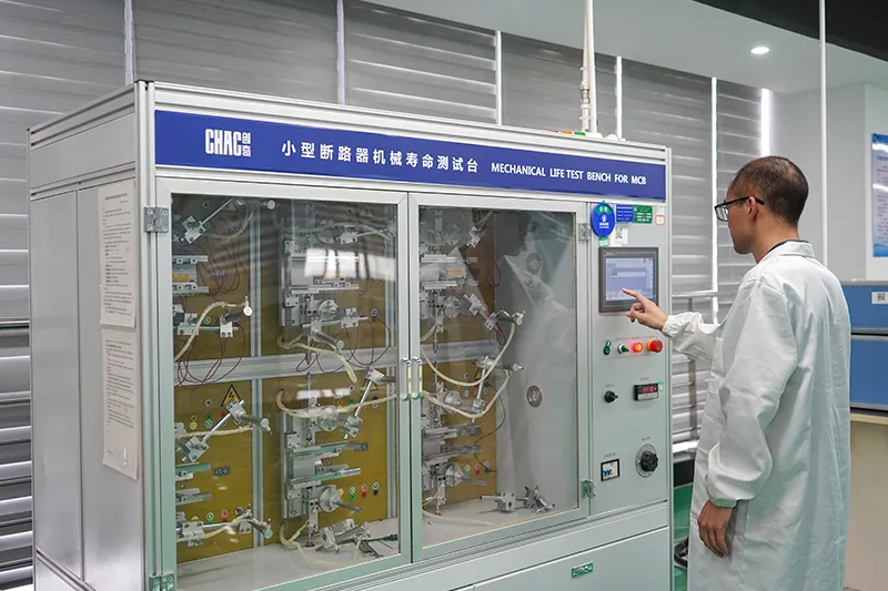
Inspekcja jakości



Ścisły system kontroli jakości zapewnia, że każdy produkt spełnia globalne standardy.
Czego możemy się dostosować?
For CQM6 projects, CHAC can review private-label marking, packaging, approved appearance options, published 16–1600A electrical configurations and technical-document requirements. Requests outside the published range are subject to engineering evaluation, testing, minimum order quantity and project feasibility.

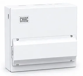
Obudowa
Projektowanie
Dostosowane wymiary obudowy, struktury i szczegóły instalacji.

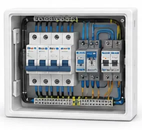
Wewnętrzny
Konfiguracja
Elastyczna struktura wewnętrzna i możliwość dostosowania układu komponentów.

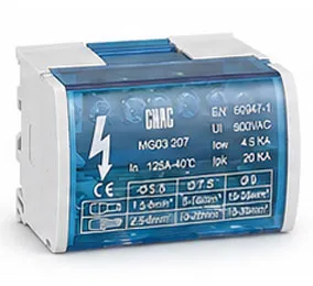
Markowanie i
Logo
Loga z własnym nadrukiem, tablice z nazwą firmy i identyfikacja marki.

Opakowanie
Projektowanie
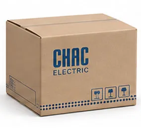
Niestandardowe opakowania, etykiety, instrukcje obsługi i rozwiązania pakowania.

Elektryczny
Konfiguracja
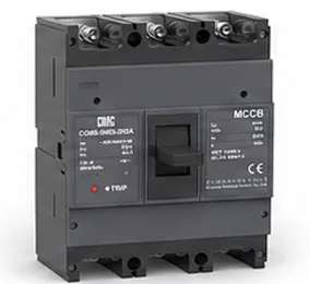
Skrojone rozwiązanie elektryczne dostosowane do wymagań aplikacji.

Certyfikacja
Obsługa klienta
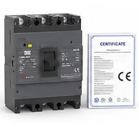
Obsługa standardów i wymagań dotyczących zgodności z wymogami rynku docelowego.
Pobierz
Przełącznik obwodowy w obudowie z formą CQM6
Pełny przegląd produktów dla komponentów elektrycznych niskiego napięcia oraz poradnik doboru produktów.
Potrzebujesz dokumentów technicznych?
Skontaktuj się z nami, aby uzyskać karty techniczne, certyfikaty, rysunki, poradniki doboru lub wsparcie w ramach projektów OEM/ODM.
CQM6 Product FAQ
What is the CQM6 MCCB used for?
The CQM6 is specified for overload and short-circuit protection in AC systems at the voltage listed for the ordered frame within the published 16–1600A range. Suitability depends on the fault study, conductor coordination, enclosure and local rules.
How does the CQM6 molded case circuit breaker work?
The protection mechanism responds to the fault conditions stated for this model: overload and short-circuit protection. Trip behaviour, settings and interruption duty must be checked against the ordered frame and product instructions.
How do I choose the CQM6 rated current and poles?
Start with the design current and conductor calculation, then choose a published current within 16–1600A and poles from 2P / 3P / 4P, depending on frame; CQM6-1600: 3P. Neutral treatment, fault level, ambient conditions and coordination also need review.
What breaking capacity should I check on the CQM6?
Use the declared C/S/M/H/L classes, with Icu up to 100kA for the listed CQM6-1600 660/690V configurations; verify the exact frame and voltage for the exact frame, voltage and configuration. The prospective short-circuit current at the installation point must be within the applicable duty; a larger ampere value alone is not a selection rule.
Can the CQM6 replace an MCB or an earth-leakage device?
An MCCB is not automatically a like-for-like replacement. The CQM6 provides overload and short-circuit protection; residual-current protection, DC interruption, adjustable settings and other functions must be confirmed separately from the project requirement.
How should the CQM6 be installed and tested?
Use only the exact model drawing, terminal identification and accessory instructions. A qualified person should verify isolation, conductor size, torque, clearances, settings, fault duty and functional tests before energising the circuit.
Confirm the Right CQM6 Configuration
Send the frame, rated current, poles, protection function, system voltage, expected fault level, destination market and quantity. CHAC will review the request against the published model range.