Imagine um técnico de manutenção substituindo um relé em uma esteira transportadora parada. O relé de reposição possui a mesma tensão da bobina, mas o intertravamento funciona de maneira diferente porque o contato auxiliar selecionado é normalmente aberto em vez de normalmente fechado. O problema reside na incompatibilidade das funções dos contatos, e não na indicação de que o novo relé esteja defeituoso.
Resumo: A símbolo de contato normalmente aberto descreve um contato que está aberto em seu estado normal especificado, quando não atuado. Um contato normalmente fechado está fechado nesse estado. Para um relé comum sem travamento, o estado normal geralmente significa que a bobina está desenergizada. O estado físico do contato também deve ser diferenciado da avaliação verdadeira ou falsa de uma instrução de CLP.
O que significa “normal” para um contato de relé ou de botão-pulsador?
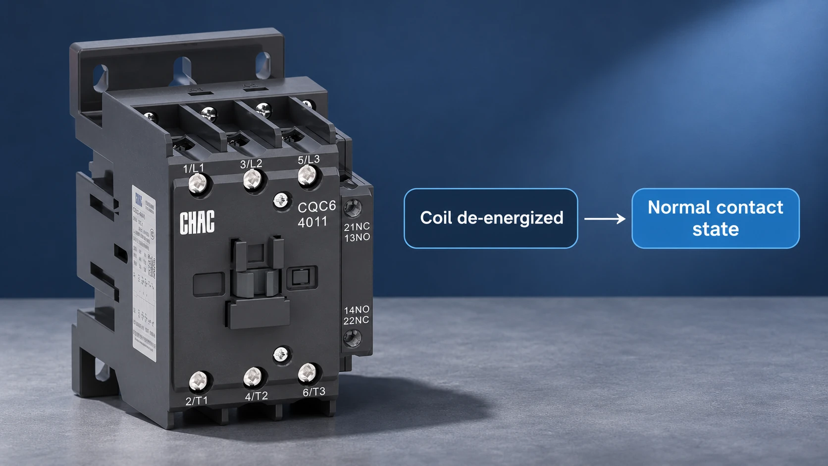
Normal não significa que a máquina esteja em operação, que haja energia disponível ou que o operador considere as condições seguras. Trata-se de um estado de referência utilizado para manter a consistência dos diagramas. Em um simples botão de retorno por mola, esse estado corresponde à posição em que o botão está solto. Em um relé eletromagnético comum, esse estado corresponde à situação em que a bobina está desenergizada.
Relés de retenção, seletoras mantidas e dispositivos com uma posição de reset definida exigem cuidados adicionais. A remoção da alimentação da bobina não garante que um contato de retenção retorne a um estado único. Leia a descrição do dispositivo e as notas do desenho antes de aplicar a regra simples de desenergização a todos os componentes.
A biblioteca de relés IEC-60617 da Autodesk identifica separadamente contatos normalmente abertos, contatos normalmente fechados, bobinas de relé e contatos de posição mantida ou com atraso. Isso é importante porque um pequeno qualificador pode alterar o significado de um símbolo que, de outra forma, seria familiar. Um contato com atraso não deve ser interpretado como um contato auxiliar instantâneo.
| Condição normal de relé não trancável | Sem contato | Contato NC | Interpretação |
|---|---|---|---|
| Bobina desenergizada | Abrir | Fechado | Condição de referência normal |
| Bobina energizada e mecanismo acionado | Fechado | Abrir | Condição acionada |
| Alimentação da bobina removida e mecanismo retornado | Abrir | Fechado | Retorne à posição normal, supondo um dispositivo de retorno por mola em funcionamento. |
Esta tabela descreve o comportamento pretendido em estado estacionário. Ela não especifica o tempo de comutação, a rebatida dos contatos, a sequência do tipo “abre-antes-de-fechar” nem um nível de desempenho de segurança. Esses detalhes dependem das características técnicas do dispositivo selecionado e, quando aplicável, de um projeto de segurança validado.
Como identificar os contatos NA e NF em um diagrama de fiação
In a common ladder representation, a normally open contact appears as two separated parallel contact lines. A normally closed representation adds a diagonal mark. IEC-style schematic contacts can instead resemble a movable contact approaching a fixed contact. The normally closed contact symbol therefore cannot be identified solely by memorizing one image from a different drawing library.
Use the project legend first, then follow the component tag. A contact assigned to relay K1 should be traced to the K1 coil and to the device contact arrangement. K1 is an illustrative tag, not a universal coding requirement. Cross-references may use sheet numbers, grid positions or contact-location tables.
A symbol for normally open contact says what the contact does in its reference state. It does not specify how much current it can switch. Main power contacts and auxiliary contacts can have different ratings, even when both are normally open and belong to the same contactor.
When drawings are copied into purchasing documents, preserve the contact qualifier, tag and reference text. A cropped image that excludes a timer mark or contact identifier can turn a clear schematic into an ambiguous replacement request.
Why a PLC contact instruction may differ from the physical switch
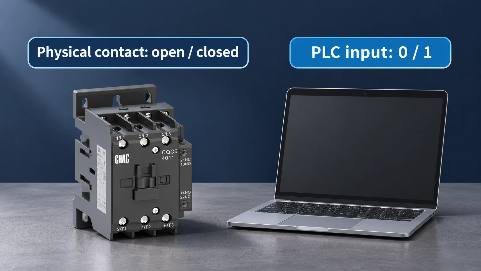
A physical switch contact creates or interrupts an electrical path. A PLC ladder instruction evaluates a stored bit or expression. Although the graphics may look similar, the instruction is not necessarily a drawing of the field switch.
For example, a physically normally closed stop contact can energize a PLC input during a healthy condition. An instruction that evaluates whether that input bit is 1 can then be true. Choosing an instruction because its graphic resembles the physical contact can produce the opposite behavior from the intended logic.
| Artigo | O que descreve | O que verificar |
|---|---|---|
| Physical NO or NC contact | Conductive state in the specified reference condition | Contact arrangement and actuator state |
| PLC input channel | Electrical input interpreted by the controller | Input type, voltage and wiring documentation |
| Input bit | Stored input status, often represented as 0 or 1 | Address mapping and any inversion or processing |
| Ladder contact instruction | A test of a bit or logical condition | The controller vendor’s instruction semantics |
Keep these four descriptions separate during troubleshooting. Record the physical actuator position, the input indication, the controller bit and the instruction result. That short sequence helps locate whether the mismatch is mechanical, electrical, a mapping issue or a software assumption.
A normal control input is not automatically a safety-rated input. A basic ladder example also does not establish a suitable emergency-stop architecture, diagnostic coverage or fault response. Those functions need their own risk assessment and applicable safety requirements.
How start and stop contacts control a motor without isolating its supply
A simple momentary start push button often uses an NO contact that closes when pressed. A simple stop circuit often uses an NC contact that opens when pressed. These examples explain the logic, but the complete machine may use interlocks, monitored devices or a safety controller that changes the required arrangement.
OSHA 29 CFR 1910.147 states that push buttons, selector switches and other control-circuit devices are not energy-isolating devices. Stopping a motor through a contactor therefore does not by itself establish an isolated work condition. The separate disconnecting equipment and site procedure still matter.
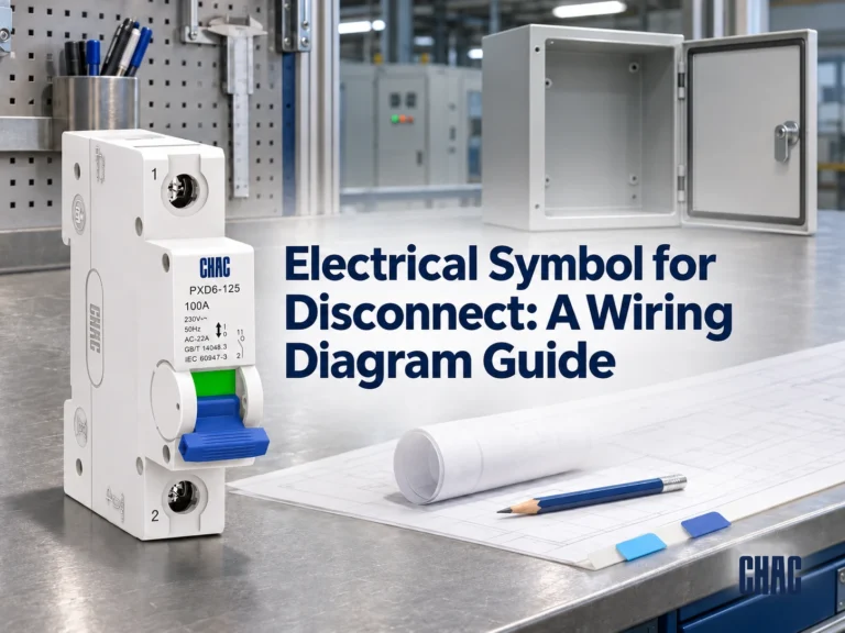
For a practical distinction between switching families, compare the PXD6-125 isolator with an AC contactor. They should be selected for their documented functions, rather than treated as interchangeable ways to draw an open circuit.
Specify coil supply and NO/NC contact requirements before ordering
A replacement request should state the exact model, coil supply, required number of NO and NC auxiliary contacts, switching duty and mounting arrangement. State whether the required contact is built into the device or supplied as a separate accessory. Do not rely on a family photograph to determine what is included.
O CHAC CQC6 contactor range includes model and accessory information that should be checked against the application. Confirm the contact block designation and terminal diagram for the exact ordered combination. A matching coil voltage alone is insufficient.
For maintenance teams, a useful spare-parts record combines the approved part number, coil data, contact arrangement and drawing revision in one entry. This reduces repeated interpretation during a breakdown. It also makes a proposed alternative easier to assess without assuming that every device in a similar housing has identical contacts.
Common questions about normally open and normally closed contacts
What does a normally open contact symbol mean?
It means the contact is open in its specified normal or unactuated state. Actuation is intended to close it, subject to the operating behavior of the particular device.
How does a normally closed contact symbol differ from a normally open symbol?
It indicates a conductive contact in the normal state, with opening on actuation. The graphical difference depends on the drawing convention, so use the legend rather than assuming every schematic uses the same diagonal mark.
Does normal mean the relay coil is de-energized?
For a typical non-latching electromagnetic relay, yes. Latching, maintained-position and specialized devices can require a different stated reference condition, which should be identified in the documentation.
What happens to a normally open contact when its relay coil is energized?
It closes when the relay mechanism operates as intended. This description assumes the correct coil supply and a functioning device, and does not define the contact’s switching delay or load rating.
How can you tell whether a contact is normally open or normally closed?
Check the manufacturer’s contact diagram and the project legend in the defined reference state. Any physical continuity testing should be performed under an appropriate safe isolation procedure, with external circuit paths accounted for.
How is a normally open push button shown in a wiring diagram?
It uses an NO contact symbol with a push-button actuation indication or designation. The normal state is generally the released condition for a momentary spring-return button.
Does a normally open PLC contact instruction always describe a physical NO switch?
No. A PLC instruction evaluates a logical condition or bit, which may be associated with many kinds of physical devices. Read the input mapping and the controller’s instruction definition separately.
Referências
- Autodesk: relay and contact symbol descriptions
- Autodesk: IEC-60617 symbol categories
- 29 CFR 1910.147: control devices and energy isolation
Specify the contact function, then verify the exact device. Send CHAC your contact arrangement and coil requirements for a model-specific quotation.