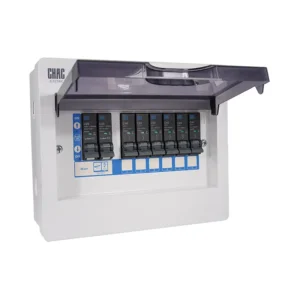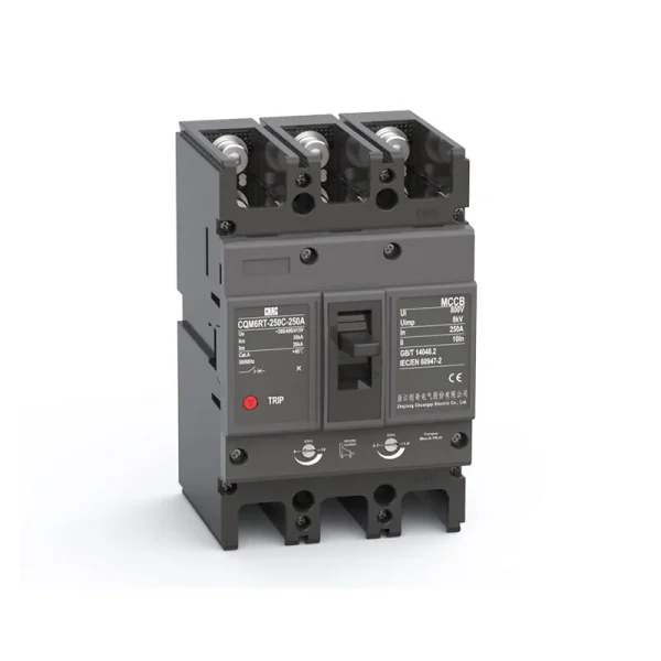
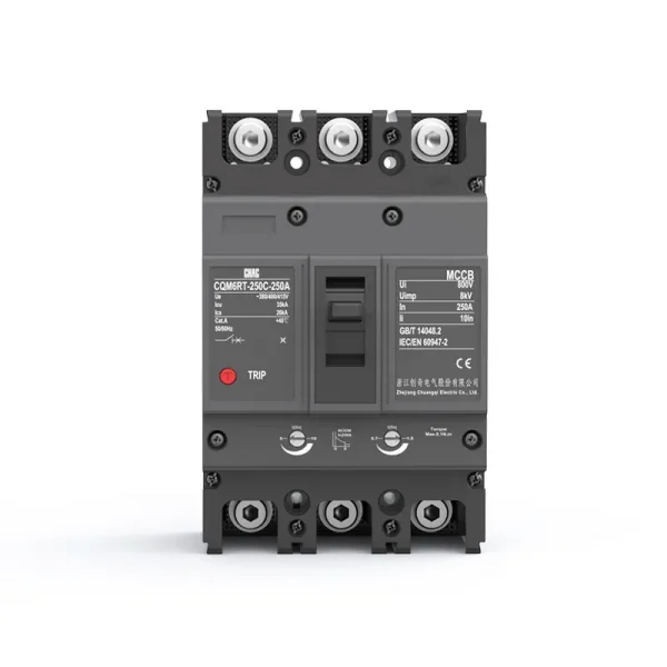

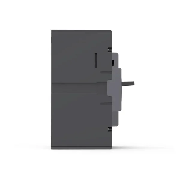
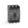
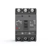


Fabricante OEM de disjuntores em caixa moldada (MCCB) magnetotérmicos ajustáveis CQM6RT
O CQM6RT MCCB provides adjustable overload and short-circuit protection within its published 63–800A range. Specification should follow the system voltage, load, conductor coordination, prospective fault current and applicable rules—not the ampere value alone.
Visão Geral do Produto
CQM6RT is a thermal magnetic circuit breaker for AC 400/415V distribution and protection applications. Its published range covers 63–800A with 3P / 4P options. Selection depends on the complete power-system design, including fault level, coordination, conductor ampacity, enclosure conditions and local rules.
The saved model record lists IEC/EN 60947 and GB/T 14048 references listed on the page as the applicable standard reference. No certification claim is added beyond the model record.
Principais Características
Aplicações Típicas
Typical applications include industrial feeders and motor circuits where field coordination requires adjustable trip settings. These are evaluation contexts rather than universal approvals. Confirm the exact frame, voltage, breaking duty, trip unit, accessories and installation method before specification.
Guia de Candidaturas e Seleção
Use the verified CQM6RT values below to create a shortlist, then validate the complete circuit. An MCCB rating does not replace conductor calculations, fault-current analysis, coordination review or local installation requirements.
| Ponto de seleção | CQM6RT reference | O que o projeto deve confirmar |
|---|---|---|
| Corrente nominal | 63–800A | Design current, conductor ampacity, installation method, temperature and grouping |
| Tensão | AC 400/415V | Sistema de alimentação e classificação de equipamento |
| Polacos | 3P / 4P | Live conductors and neutral treatment |
| Trip / protection | adjustable thermal Ir and magnetic Im | Load profile, fault response and coordination |
| Capacidade de corte | C/S/M classes up to 75kA, according to frame and ordered configuration | Prospective short-circuit current at the installation point |
Fixed vs Adjustable Protection
A fixed thermal-magnetic device can suit a stable design, while an adjustable trip unit may help coordination when the project study requires field settings.
Trip Coordination
Compare MCCB Options →
MCCB vs MCB
An MCCB is normally evaluated for higher current, fault duty or accessory flexibility; an MCB may be more suitable for compact final circuits.
Current & Fault Duty
Compare MCCB and MCB →
Icu vs Ics
The saved data for CQM6RT lists C/S/M classes up to 75kA, according to frame and ordered configuration. Match the declared duty to the prospective short-circuit current and continuity objective.
Short-Circuit Study
Review Technical Support →
Pole and Neutral Arrangement
Published pole options are 3P / 4P. Confirm which conductors must be switched, protected and isolated together.
System Arrangement
View MCCB Range →
Guia de Encomenda
- State the exact model: CQM6RT.
- Provide frame and rated current within the published range: 63–800A.
- Confirm poles: 3P / 4P.
- Specify the trip unit or protection function: adjustable thermal Ir and magnetic Im.
- Provide system voltage, frequency, application, expected fault level, destination market and quantity.
- List required accessories, terminals, documents and any approved OEM/ODM marking or packaging requirements.
Verificações de Instalação e Coordenação
- Use the exact model drawing and instructions; do not infer terminal positions, supply direction or accessory compatibility from another MCCB.
- Verify conductor material and cross-section against the circuit calculation, terminal data, temperature and grouping.
- Confirm Icu/Ics or DC fault duty, upstream/downstream coordination, enclosure conditions, altitude and clearances.
- Installation, isolation, testing and maintenance must be performed by qualified personnel under applicable rules.
Accessory List
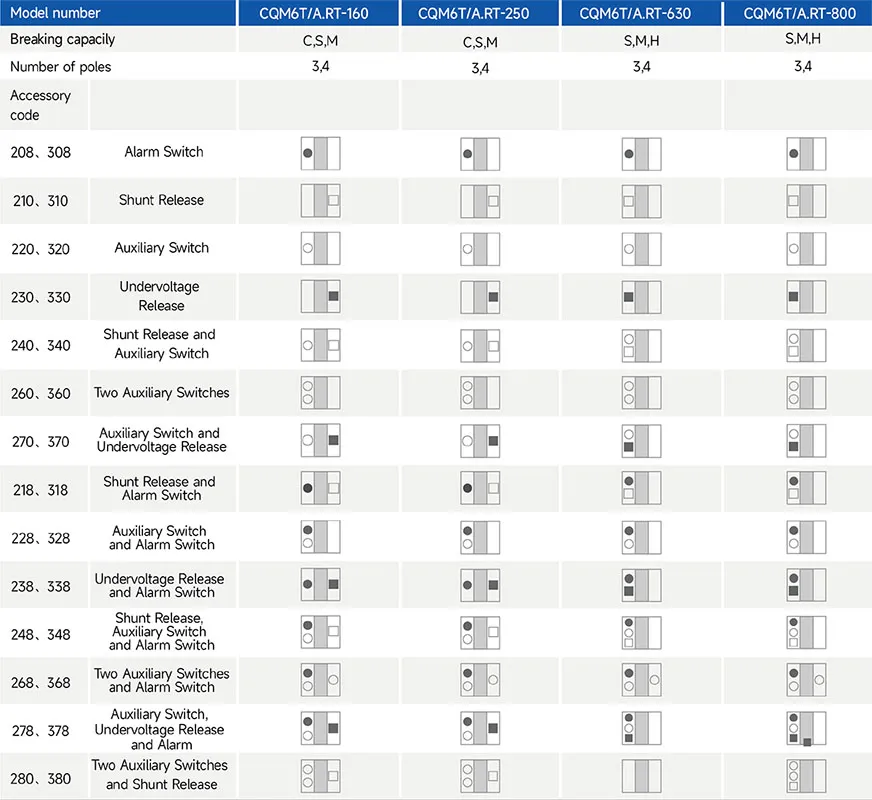
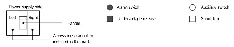
1.MH can provide thre new products right auxiary svitch,left stunt and left undervoltape for custorrersto chose.
2.In 220,320,240,340,270,370 specincafons,the auxilary swichcanbe used for Mopairs of swches,which shoukdbe specfied when ordering.
Guia de Seleção

| Product code ① | Shell frame grade ② | Shell frame grade ③ | Breaking capacity ④ | ||||
| CQM6 | RT | 160 | C | ||||
| Molded case circuit breaker | RT stands for thermomagnetic ally adjustable T、 A stands for single adjustable (i.e., thermally adjustable/magnetically fixed). |
C | S | M | H | ||
| 160 | 160 | 25/18 | 35/25 | 50/35 | / | ||
| 250 | 250 | 25/18 | 35/25 | 50/35 | / | ||
| 630 | 630 | / | 35/25 | 50/35 | 75/50 | ||
| 800 | 800 | / | 35/25 | 50/35 | 75/50 | ||
| Operating method ⑤ | The number of poles ⑥ | Decoupler method and internal accessories ⑦ | Rated current A | |
| P | 4 | 300 | 125A | |
| P: Motorized operation Z: Turn the handle W: Direct operation Delectric operation DC1DC 2,DC3 |
2: 2-pole 3: 3-pole 4: 4-pole |
The first digit indicates the type of detent 2: Instantaneous detent only 3: Duplicate detent Note: The last two digits are the accessory designator (see accessory table). |
160 | 32,40,50,63,80,100,125,140,160 |
| 250 | 100,125,140,160,180,200,225,250 | |||
| 630 | 250,315,350,400,500,630 | |||
| 800 | 500,630,700,800 | |||
| Application⑧ | Optional code for Level 4 products⑨ | Special code⑩ |
| 2 | A | I |
| 1:For power distribution | A:N-pole unprotected,not combinable A | I:Overload alarm non |
| 2:For motor protection | B:N-pole unprotected,combinable | trip function |
| Accessory Voltage⑪ | Motorized operating voltage⑫ | Installation⑬ | Whether to install a terminal block⑭ | |||
| Q1 | D1 | Q | 2 | |||
| Undervoltage detent UVT | Shunt release Shunt |
Auxiliary alarm Auxiliary |
DC1 | DC3 D5: AC230V | Q: Front of plate H: Rear of plate C: Inserted |
1: No installation 2: Installation |
| Q1: AC220V | F1: AC220V | J1: AC125V | D1: AC220V | D6: AC110V | ||
| Q2: AC240V | F2: AC380V | J2: AC250V | D2: AC230V | D7: DC220V | ||
| Q3: AC380V | F3: DC110V | J3: DC125V | D3: AC380V | D8: DC110V | ||
| Q4: AC415V | F4: DC24V | J4: DC24V | D4: AC400V | D9: AC110~240V | ||
| D10: DC100~220V | ||||||
Main Technical Parameters
| Número do modelo | CQM6T/A.RT-160 | CQM6T/A.RT-250 | ||||||
| Rated current of frame level Inm(A) | 160 | 250 | ||||||
| Número de polos | 3, 4 | 3, 4 | ||||||
| Rated current In(A),at 40℃,50℃,55℃ | 63,80,100,125,160 | 125,140,160,180,200,225,250 | ||||||
| Rated operating voltage Ue(V),AC 50/60Hz | 400/415 | 400/415 | ||||||
| Rated insulation voltage Ui (V) | 800 | 800 | ||||||
| Rated impulse withstand voltage Uimp(KV) | 8 | 8 | ||||||
| Breaking capacity designation | C | S | M | C | S | M | ||
| Short-circuit breaking capacity Icu/Ics(kA) | AC400/415V | 25/18 | 35/25 | 50/35 | 25/18 | 35/25 | 50/35 | |
| Selectivity category | A | A | A | A | A | A | ||
| Number of operating cycles(cycle) | ON | 6000 | 6000 | |||||
| OFF | 10000 | 10000 | ||||||
| Trip mechanisms and protection types |
Magnetic trip | Power distribution protection | ● | ● | ● | ● | ● | ● |
| Motor protection | ● | ● | ● | ● | ● | ● | ||
| Thermal-magnetic trip | Power distribution protection | ● | ● | ● | ● | ● | ● | |
| Motor protection | ● | ● | ● | ● | ● | ● | ||
| Accessory | Auxiliary contacts | ● | ● | ● | ● | ● | ● | |
| Alarm contacts | ● | ● | ● | ● | ● | ● | ||
| Shunt disconnect | ● | ● | ● | ● | ● | ● | ||
| Undervoltage detent | ● | ● | ● | ● | ● | ● | ||
| Manual operating mechanism | ● | ● | ● | ● | ● | ● | ||
| Motorized operating mechanism | ● | ● | ● | ● | ● | ● | ||
| Backplane wiring | ● | ● | ● | ● | ● | ● | ||
| Inserted | ● | ● | ● | ● | ● | ● | ||
| Coupling plate | ● | ● | ● | ● | ● | ● | ||
| Partition between phases | ● | ● | ● | ● | ● | ● | ||
| Derivative products | Dedicated for prepayment electric meters | ● | ● | ● | ● | ● | ● | |
| Overload alarm without trip | ● | ● | ● | ● | ● | ● | ||
| Overall dimensions (mm) (a-b-c-ca) |
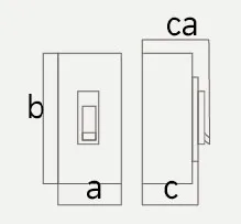 |
3 P | 90-155-70-94 | 90-155-84-109 | 105-165-70-96 | 105-165-93-120 | ||
| 4 P | 120-155-70-94 | 120-155-84-109 | 140-165-70-96 | 140-165-93-120 | ||||
Note: ● for optional accessories;“-”for no optional accessories.
| Número do modelo | CQM6T/A.RT-630 | CQM6T/A.RT-800 | ||||||
| Rated current of frame level Inm(A) | 630 | 800 | ||||||
| Número de polos | 3, 4 | 3, 4 | ||||||
| Rated current In(A),at 40℃,50℃,55℃ | 250,315,350,400,500,630 | 500,630,700,800 | ||||||
| Rated operating voltage Ue(V),AC 50/60Hz | 400/415 | 400/415 | ||||||
| Rated insulation voltage Ui (V) | 800 | 800 | ||||||
| Rated impulse withstand voltage Uimp(KV) | 8 | 8 | ||||||
| Breaking capacity designation | S | M | H | S | M | H | ||
| Short-circuit breaking capacity Icu/Ics(kA) | AC400/415V | 35/25 | 50/35 | 75/50 | 35/25 | 50/35 | 75/50 | |
| Selectivity category | A | A | A | A | A | A | ||
| Number of operating cycles(cycle) | ON | 3000 | 3000 | |||||
| OFF | 8000 | 8000 | ||||||
| Trip mechanisms and protection types |
Magnetic trip | Power distribution protection | ● | ● | ● | ● | ● | ● |
| Motor protection | ● | ● | ● | ● | ● | ● | ||
| Thermal-magnetic trip | Power distribution protection | ● | ● | ● | ● | ● | ● | |
| Motor protection | ● | ● | ● | ● | ● | ● | ||
| Accessory | Auxiliary contacts | ● | ● | ● | ● | ● | ● | |
| Alarm contacts | ● | ● | ● | ● | ● | ● | ||
| Shunt disconnect | ● | ● | ● | ● | ● | ● | ||
| Undervoltage detent | ● | ● | ● | ● | ● | ● | ||
| Manual operating mechanism | ● | ● | ● | ● | ● | ● | ||
| Motorized operating mechanism | ● | ● | ● | ● | ● | ● | ||
| Backplane wiring | ● | ● | ● | ● | ● | ● | ||
| Inserted | ● | ● | ● | ● | ● | ● | ||
| Coupling plate | ● | ● | ● | ● | ● | ● | ||
| Partition between phases | ● | ● | ● | ● | ● | ● | ||
| Derivative products | Dedicated for prepayment electric meters | ● | ● | ● | ● | ● | ● | |
| Overload alarm without trip | ● | ● | ● | ● | ● | ● | ||
| Overall dimensions (mm) (a-b-c-ca) |
|
3 P | 210-275-105-155 | 210-275-105-155 | ||||
| 4 P | 280-275-105-155 | 280-275-105-155 | ||||||
Note: ● for optional accessories;“-”for no optional accessories.
Características operacionais
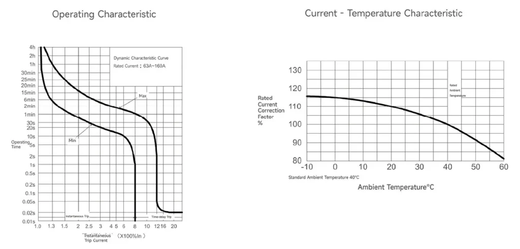
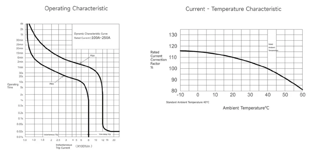
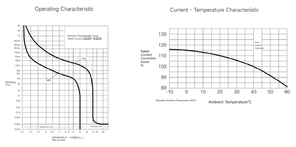
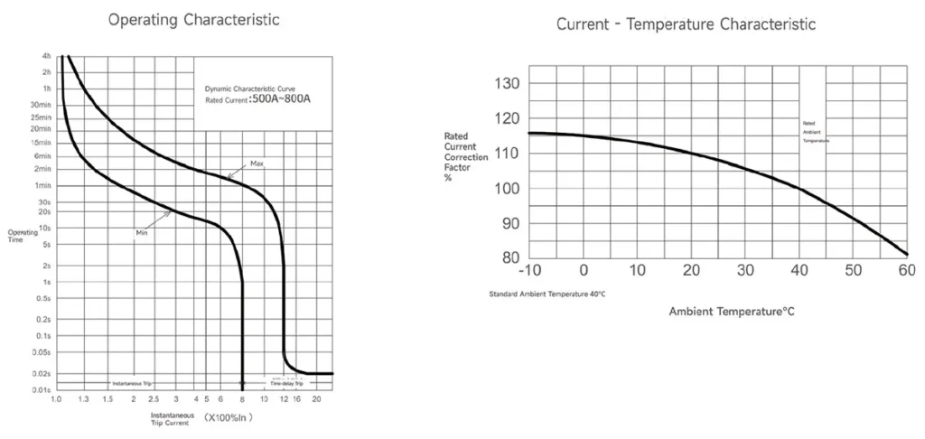
1.The inverse time operating characteristics of power distribution circuit breakers when all poles are energized simultaneously at anambient airtemperature of +40℃(with no humidity compensation)are shown in the following table:
| Test current designation | Setting current multiple | Conventional time | Initial state |
| In≤63 In > 63 | |||
| Conventional non-tripping current | 1.05 | ≥1h ≥2h | Cool state |
| Conventional tripping current | 1.30 | <1h<2h | Hot state |
2.The inverse time action characteristics of circuit breakers for motor protection without humidity compensation when all poles areenergizedsimultaneously at an ambient air temperature of +40℃ are shown in the following table.
| Test current designation | Setting current multiple | Conventional time | Initial state |
| In≤800 | |||
| Conventional non-tripping current | 1.0 | ≥2h | Cool state |
| Conventional tripping current | 1.20 | <2h | Hot state |
3.Action characteristics under short-circuit condition:The short-circuitcurentsetting value of the instantaneous tripper of the circuitbreaker for power distribution is 10ln.
The short-circuit current setting value of the instaneous tripper of the circuit breaker for motorprotection is 12ln.
The accuracy of the short-circuit curent setting value of the instantarheous tripper is 20%of the short-circuit currentsetting value.
CQMGT/A.RT-160 Operating Characteristic Curve
CQMGT/A.RT-250 Operating Characteristic Curve
CQMGT/A.RT-630 Operating Characteristic Curve
CQMGT/A.RT-800 Operating Characteristic Curve
Outline and Installation Dimensions(mm)
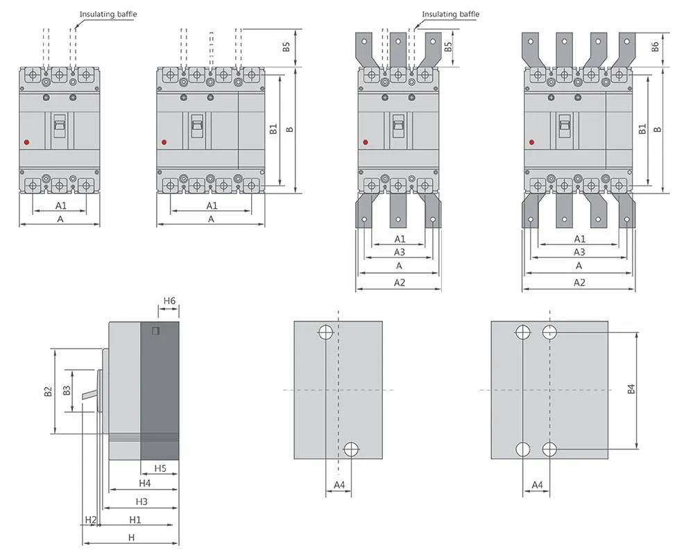
| Molded case circuit breaker | Overall dimension | Installation dimensions | Bolt | |||||||||||||||||||||
| A | A1 | A2 | A3 | B | B1 | B2 | B3 | B5 | B6 | H | H1 | H2 | H3 | H4 | H5 | H6 | A4 | B4 | ||||||
| 3P | 4P | 3P | 4P | 3P | 4P | 3P | 4P | |||||||||||||||||
| CQM6T/A.RT-160CS | 90 | 120 | 60 | 90 | – | – | – | – | 155 | 134 | 103 | 50 | 50 | – | 94 | 72 | 4 | 70 | 61 | 41 | 24 | 30 | 132 | M8 |
| CQM6T/A.RT-160M | 90 | 120 | 60 | 90 | – | – | – | – | 155 | 134 | 103 | 50 | 50 | – | 109 | 83 | 4 | 83 | 76 | 24.5 | 24.5 | 30 | 132 | M8 |
| CQM6T/A.RT-250CS | 105 | 140 | 70 | 105 | – | – | – | – | 165 | 144 | 103 | 50 | 100 | – | 96 | 72 | 4 | 70 | 61 | 46 | 24 | 35 | 126 | M8 |
| CQM6T/A.RT-250M | 105 | 140 | 70 | 105 | – | – | – | – | 165 | 144 | 102 | 50 | 110 | – | 120 | 95 | 4 | 91 | 84 | 22.5 | 24 | 35 | 126 | M8 |
| CQM6T/A.RT-630SMH | 140 | 185 | 88 | 132 | 140 | 196 | 112 | 168 | 257 | 230 | 179 | 90 | 110 | 42 | 155 | 107 | 5 | 105 | 97 | 64 | 35 | 44 | 194 | M10 |
| CQM6T/A.RT-800SMH | 210 | 280 | 140 | 210 | 180 | 250 | 140 | 210 | 275 | 243 | 192 | 90 | 110 | 87 | 155 | 107 | 5 | 104 | 97 | 65 | 24 | 70 | 242.5 | M12 |
Porquê escolher a CHAC
Com mais de 30 anos de experiência em fabrico, mais de 1100 funcionários, mais de 100 milhões de postes
Com uma capacidade anual e um processo de produção automatizado 90%, a CHAC garante uma capacidade de produção estável e rigorosos
Controlo de qualidade para clientes OEM/ODM globais. O nosso sistema de fabrico interno suporta a longo prazo
cooperação para marcas elétricas, importadores e distribuidores.

30+
ANOS DE EXPERIÊNCIA
Especializado em fabrico de baixa tensão elétrica

1100+
FUNCIONÁRIOS
Equipa profissional garante qualidade e entrega estáveis

100M+
CAPACIDADE ANUAL DE POSTOS
Capacidade de produção em larga escala para satisfazer a procura global

90%
PRODUÇÃO AUTOMATIZADA
Automação avançada para alta eficiência e consistência

Linha de Montagem Automatizada

Laboratório de Ensaios
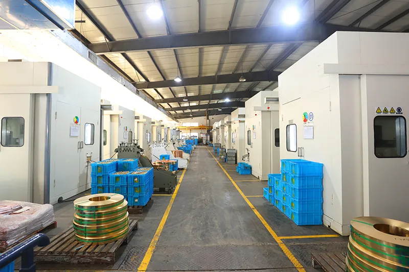
Injeção e Estampagem
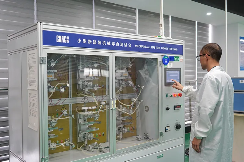
Inspeção de Qualidade



Um rigoroso sistema de controlo de qualidade garante que cada produto cumpre as normas globais.
O que podemos personalizar?
For CQM6RT projects, CHAC can review private-label marking, packaging, approved appearance options, published 63–800A electrical configurations and technical-document requirements. Requests outside the published range are subject to engineering evaluation, testing, minimum order quantity and project feasibility.

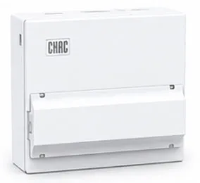
Recinto
Design
Tamanhos de caixas personalizadas, estruturas e detalhes de instalação.

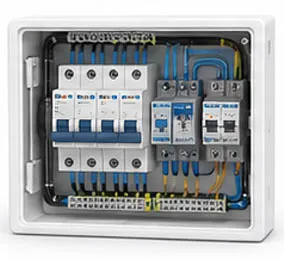
Interno
Configuração
Layout interno flexível e opções de arranjo de componentes.

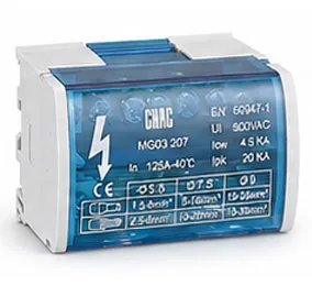
Branding &
Logótipo
Logótipos de marca própria, placas de identificação e identificação da marca.

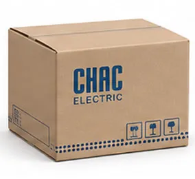
Embalagem
Design
Caixas personalizadas, etiquetas, manuais e soluções de embalagem.

Elétrico
Configuração
Instalação elétrica à medida com base nos requisitos da aplicação.
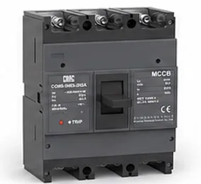

Certificação
Apoio
Apoio a normas e requisitos de conformidade do mercado-alvo.
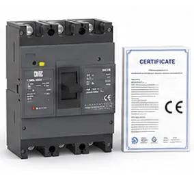
Transferir
Disjuntor de Caixa Moldada Série CQM6
Visão geral completa de componentes elétricos de baixa tensão e referência para seleção de produtos.
Precisa de Documentos Técnicos?
Contacte-nos para folhas de dados, certificados, desenhos, orientação de seleção ou suporte a projetos OEM/ODM.
CQM6RT Product FAQ
What is the CQM6RT MCCB used for?
The CQM6RT is specified for adjustable overload and short-circuit protection in AC 400/415V systems within the published 63–800A range. Suitability depends on the fault study, conductor coordination, enclosure and local rules.
How does the CQM6RT molded case circuit breaker work?
The protection mechanism responds to the fault conditions stated for this model: adjustable overload and short-circuit protection. Trip behaviour, settings and interruption duty must be checked against the ordered frame and product instructions.
How do I choose the CQM6RT rated current and poles?
Start with the design current and conductor calculation, then choose a published current within 63–800A and poles from 3P / 4P. Neutral treatment, fault level, ambient conditions and coordination also need review.
What breaking capacity should I check on the CQM6RT?
Use the declared C/S/M classes up to 75kA, according to frame and ordered configuration for the exact frame, voltage and configuration. The prospective short-circuit current at the installation point must be within the applicable duty; a larger ampere value alone is not a selection rule.
Can the CQM6RT replace an MCB or an earth-leakage device?
An MCCB is not automatically a like-for-like replacement. The CQM6RT provides adjustable overload and short-circuit protection; residual-current protection, DC interruption, adjustable settings and other functions must be confirmed separately from the project requirement.
How should the CQM6RT be installed and tested?
Use only the exact model drawing, terminal identification and accessory instructions. A qualified person should verify isolation, conductor size, torque, clearances, settings, fault duty and functional tests before energising the circuit.
Confirm the Right CQM6RT Configuration
Send the frame, rated current, poles, protection function, system voltage, expected fault level, destination market and quantity. CHAC will review the request against the published model range.