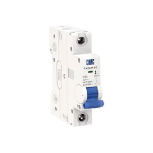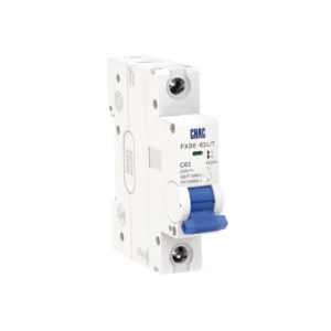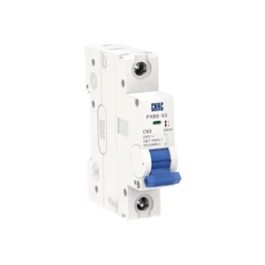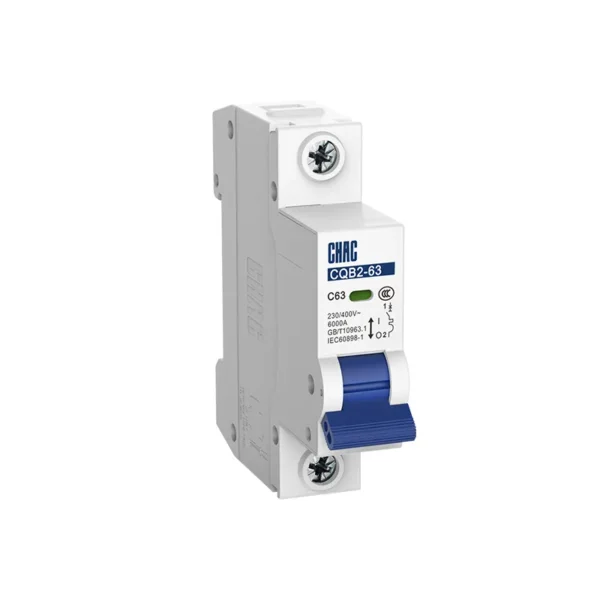
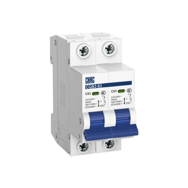
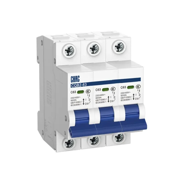
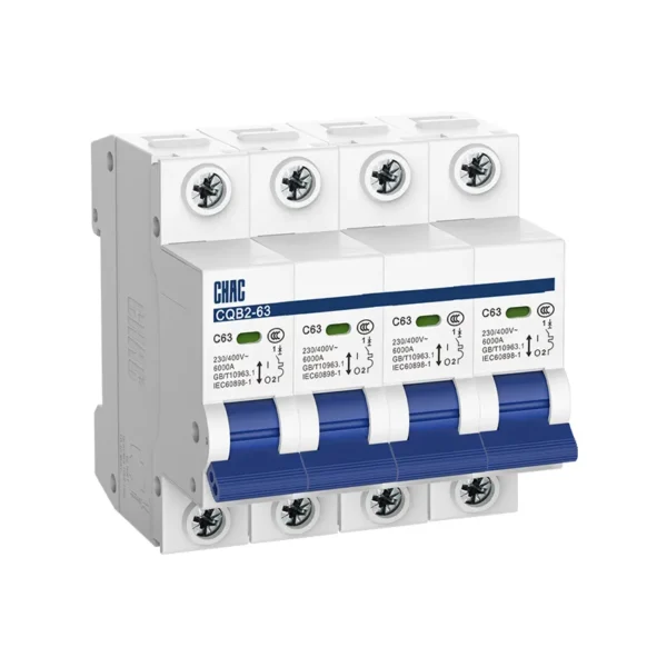
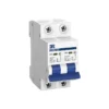
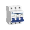
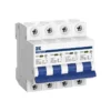
CQB2-63 Miniature Circuit Breaker
The CQB2-63 miniature circuit breaker is designed for overload and short-circuit protection in 230/400V AC final-distribution systems. It covers 6A to 63A, B, C and D tripping curves, and 1P, 1P+N, 2P, 3P, 3P+N and 4P configurations. Its rated short-circuit breaking capacity is 6kA, with Icn equal to Ics. The series is specified to IEC 60898-1 and the model page lists CCC certification. It gives distributors, panel builders and OEM buyers a clearly defined platform for residential, commercial and light-industrial distribution projects.
Product Overview
The CQB2-63 is a 6kA miniature circuit breaker for final-distribution circuits that require overload and short-circuit protection. It is rated for 230/400V AC at 50 or 60Hz and is available from 6A to 63A. Buyers can specify B, C or D tripping characteristics and choose 1P, 1P+N, 2P, 3P, 3P+N or 4P configurations to suit the circuit and local installation rules.
For distributors, panel builders and electrical OEMs, the series combines a consistent 6kA breaking-capacity platform with a broad configuration range. Selection should still be based on conductor ampacity, load behavior, prospective short-circuit current, ambient conditions and the destination market. The CQB2-63 is specified to IEC 60898-1, and CCC is the certification confirmed for this model on the current product page.
Key Features
Typical Applications
The CQB2-63 is intended for final circuits in residential, commercial and light-industrial distribution systems. Typical uses include lighting, socket-outlet, small HVAC, pump and other branch circuits when the selected rating and trip curve match the conductor, load and fault-current study. An MCB primarily protects the circuit conductors, so selection must account for cable size, installation method, ambient temperature, grouping and upstream coordination rather than the appliance name alone.
Applications and Selection Guide
| Selection item | How to evaluate it | CQB2-63 options |
|---|---|---|
| Rated current | Confirm design current, conductor ampacity, installation method, ambient temperature and grouping. Do not increase the breaker rating to solve repeated tripping without diagnosing the cause. | 6A, 10A, 16A, 20A, 25A, 32A, 40A, 50A, 63A |
| Tripping curve | Compare normal operating current, starting or inrush current and the fault-current level needed for timely magnetic operation. | B, C or D |
| Number of poles | Match the supply system and determine which live conductors—and, where required, the neutral—must be disconnected together. | 1P, 1P+N, 2P, 3P, 3P+N, 4P |
| Breaking capacity | Verify that the prospective short-circuit current at the installation point does not exceed the device rating. Use another protective solution if the study requires a higher value. | 6kA, Icn = Ics |
| Standard and market documents | Check the product standard, destination-market rules and the exact documents required by the customer or approval body. | IEC 60898-1; CCC confirmed on this page |
Compare breaking capacity, tripping curves, pole configurations and protection functions before selecting the right miniature circuit breaker for your application.
6kA vs 10kA MCB
Select breaking capacity according to the prospective short-circuit current at the installation point, not only the rated current of the circuit.
B Curve vs C Curve vs D Curve
Select the tripping curve according to load inrush characteristics, not by current rating alone.
1P+N vs 2P MCB
Both options can be used in single-phase circuits, but their switching and protection arrangements are different.
MCB vs RCBO
An MCB protects against overload and short circuit, while an RCBO also provides residual-current protection.
Need Help Selecting an MCB Configuration?
Share your pole configuration, rated current, tripping curve and quantity. Our team will help confirm a suitable CQB2-63 option for your application.
Installation and Ordering Details to Confirm
Professional MCB product pages commonly identify operating and storage conditions, mounting format, conductor capacity, tightening torque, dimensions and weight. These values vary by product family, rated current and pole configuration, so figures from another brand or series should not be applied to the CQB2-63. Confirm the following items on the approved CQB2-63 datasheet, installation instructions or project quotation before final selection:
For a project-specific confirmation, send CHAC the rated current, trip curve, pole configuration, destination market, expected quantity and panel or conductor constraints.
How to choose between B, C and D curves
The curve identifies the instantaneous magnetic-trip range, not a general quality grade. The CQB2-63 tripping table gives 3–5 × In for B curve, 5–10 × In for C curve and 10–20 × In for D curve. B curve is commonly considered for low-inrush circuits, C curve for moderate inrush, and D curve for higher-inrush equipment. The final choice must still provide adequate fault protection; selecting a slower curve only to avoid nuisance trips can delay operation when fault current is limited.
How to choose the pole configuration
Select the pole arrangement from the actual supply and isolation requirements rather than from panel space alone. A 1P device switches one conductor, while multi-pole versions provide mechanically linked operation for the specified conductors. Neutral switching and isolation rules vary by system and market, so 1P+N, 3P+N and 4P options should be confirmed against the project drawings and local requirements.
When 6kA is not enough
A 6kA marking means the breaker is rated to interrupt a prospective short-circuit current of up to 6,000A under the applicable test conditions; it is not the normal load-current rating. If the calculated or measured prospective fault current at the installation point exceeds 6kA, use equipment with a suitable rating or a verified coordinated solution rather than assuming every MCB is interchangeable.
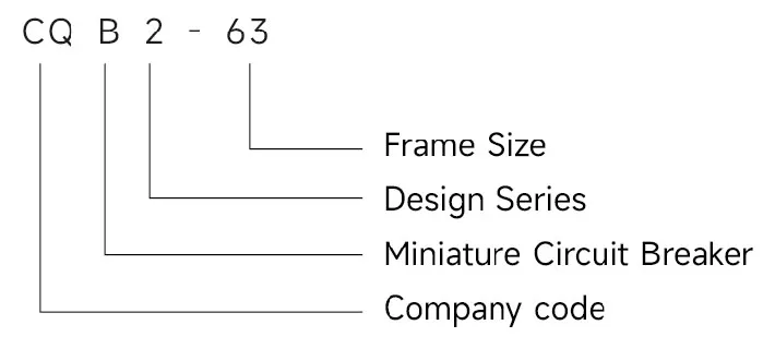
Type designation
Tripping curves

Dimensions(unit:mm)

Technical Specifications
| Parameter | |
| Rated insulation voltage | 500 V |
| Rated impulse withstand voltage (Uimp) | 4000 V |
| Rated current | 6A, 10A, 16A, 20A, 25A, 32A, 40A, 50A, 63A |
| Rated frequency | 50 Hz / 60 Hz |
| Number of poles | 1P, 1P+N, 2P, 3P, 3P+N, 4P |
| Rated breaking capacity (Icn = Ics) | 6000 A |
| Mechanical life | ≥ 10,000 operations |
| Electrical life | ≥ 6,000 operations |
| Tripping characteristics | B, C, D |
| Terminal center distance | 45 mm |
| Degree of protection | IP20 |
| Standards | IEC 60898-1, GB/T 10963.1 |
| Certification | CCC |
Table 1 Tripping characteristics (Reference temperature 30°C)
| Item | Tripping Curve | Test current In(A) | Initial Status | Time limit for tripping or non-tripping | Expected result | Remarks |
| a | B、C、D | 1.13ln | Cold | t≤1h | Non-tripping | Current smoothly rises to specified value within 5s |
| b | B、C、D | 1.45ln | Following item a test | t<1h | Tripping | |
| c | B、C、D | 2.55ln | Cold | 1s<t<60s(ln≤32A) 1s<t<120s(ln>32A) |
Tripping | |
| d | B | 3In | Cold | t≤0.1s | Non-tripping | Switch on the power supply by closing the auxiliary switch |
| C | 5In | |||||
| D | 10ln | |||||
| e | B | 5In | Cold | t<0.1s | Tripping | Switch on the power supply by closing the auxiliary switch |
| C | 10ln | |||||
| D | 20ln |
Note: The term “cold” means that the test is carried out at a reference calibration temperature without load before the test.
Conductor requirements and cross section
| Copper cross-section(mm²) | Rated current In(A) |
| 1 | In≤6 |
| 1.5 | 6 In≤13 |
| 2.5 | 13 In≤20 |
| 4 | 20 In≤25 |
| 6 | 25 In≤32 |
| 10 | 32 In≤50 |
| 16 | 50 In≤63 |
Why Choose CHAC
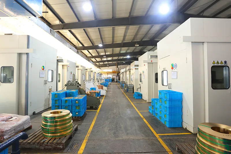
With 30+ years of manufacturing experience, 1100+ employees, 100M+ poles
annual capacity and 90% automated production, CHAC provides stable production capacity and strict
quality control for global OEM/ODM customers. Our in-house manufacturing system supports long-term
cooperation for electrical brands, importers and distributors.

30+
YEARS EXPERIENCE
Specialized in low-voltage electrical manufacturing

1100+
EMPLOYEES
Professional team ensures stable quality and delivery

100M+
POLES ANNUAL CAPACITY
Large-scale production capacity to meet global demand

90%
AUTOMATED PRODUCTION
Advanced automation for high efficiency and consistency

Automated Assembly Line

Testing Laboratory
Injection & Stamping

Quality Inspection



Strict quality control system ensures every product meets global standards.
What Can We Customize?
CQB2-63 OEM/ODM options are reviewed per project rather than assumed to be available for every configuration. The published 6–63A ratings, B/C/D curves and listed pole arrangements are the starting platform. Marking, packaging, labels, manuals, appearance requests, engineering work and certification support depend on technical feasibility, order quantity, tooling requirements and the destination market. Changes to internal construction, breaking capacity, terminals, dimensions or certified ratings require separate engineering and compliance confirmation.

Logo & Branding
Logo and marking requests are reviewed against the available print area, required regulatory markings and approved artwork.


Packaging
Customization
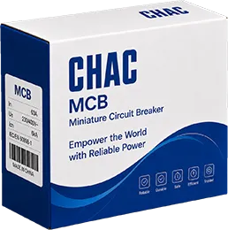
Color boxes, cartons, labels and manuals can be reviewed by language, destination market and order quantity.

Electrical
Customization
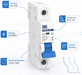
Available rated-current, pole and B/C/D curve combinations are reviewed within the validated CQB2-63 platform.

Product
Appearance
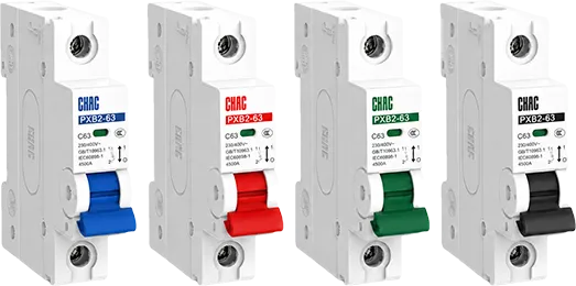
Housing or handle color requests require technical, material, tooling and compliance review before sampling.

Certification
Support
Destination-market documents and certification requirements are reviewed for the exact model and configuration before sample approval.


Engineering
Development
Drawing, prototype and validation support is scoped per project; internal construction or rating changes are not assumed.

Download
CQB2 Series Miniature Circuit Breaker
Complete product overview for low-voltage electrical components and product selection reference.
Need Technical Documents?
Contact us for datasheets, certificates, drawings, selection guidance or OEM/ODM project support.
CQB2-63 Miniature Circuit Breaker FAQ
How to choose the correct MCB?
Start with the conductor ampacity and circuit design current, then check the supply voltage, pole configuration, load inrush, ambient conditions and prospective short-circuit current. For the CQB2-63, select within 6–63A, match the B/C/D curve to the load and fault conditions, and verify that the installation point does not exceed the 6kA breaking-capacity rating.
What are the different types of poles in an MCB?
MCBs may switch one or several conductors together. The CQB2-63 is offered in 1P, 1P+N, 2P, 3P, 3P+N and 4P configurations; the correct option depends on the single- or three-phase system and whether the neutral must be switched or isolated under the applicable rules.
What does kA mean on circuit breakers?
kA indicates short-circuit breaking capacity, not continuous load current. The CQB2-63 has a 6kA rating, meaning it is designed to interrupt up to 6,000A of prospective short-circuit current under the stated IEC 60898-1 test conditions; the installation must be checked to confirm that this rating is sufficient.
What is the difference between a 1-pole MCB and a 2-pole MCB?
A 1-pole MCB operates one conductor, while a 2-pole MCB provides linked operation across two conductors. The choice depends on the supply arrangement and disconnection rules; two unrelated single-pole breakers should not be assumed to provide the same common operation as a purpose-designed 2P device.
What is the C curve and D curve in an MCB?
For the CQB2-63, the published instantaneous magnetic-trip ranges are 5–10 × In for C curve and 10–20 × In for D curve. D curve tolerates more starting current, but it should only be used when the load profile and available fault current allow the protective device to operate within the required disconnection time.
When should a B-curve MCB be used?
B curve is generally considered for circuits with relatively low starting or inrush current. The CQB2-63 data gives a B-curve magnetic-trip range of 3–5 × In; engineers should still confirm conductor protection, normal transients and fault-loop conditions rather than choosing the curve from the load label alone.
Build the Right CQB2-63 Configuration for Your Market
Send us your required current rating, B/C/D curve, pole configuration, destination market and estimated quantity. CHAC will review the specification and provide the relevant technical documents and commercial proposal.