
حاسبة حجم الكابل — نحاس/بولي فينيل كلوريد
حجم كابلات النحاس/PVC بالملليمتر المربع باستخدام القدرة التحملية المصححة وانخفاض الجهد المقاوم. يغطي ثلاثة موصلات محملة في الهواء بطرق A1، A2، B1، B2 وC.
ابحث عن أصغر موصل نحاسي مغلف بالبولي فينيل كلوريد (PVC) يحقق متطلبات التصنيف الحالي وانخفاض الجهد الناتج عن المقاومة المدخلة للدائرة ثلاثية الأطوار المتوازنة.
النتيجة
مرجع موصل النحاس/البولي فينيل كلوريد
6.00مم²فحوصات الجدول والانخفاض المقاوم فقط6 مم² هو أصغر موصل مدرج يلبي حدود القدرة الحالية وانخفاض الجهد المقاوم المدخلة.
Iz = Itable × ktemperature × kother; Ib ≤ In ≤ Iz; ΔV% = 100 × √3 × I × ρ70 × L / (S × V)الشكل المحدد G20 يغطي صفوف النحاس/PVC لثلاثة موصلات مُحمَّلة عند درجة حرارة هواء مرجعية قدرها 30°C، وفقًا للطرق A1/A2/B1/B2/C. يعتمد الانخفاض على مقاومة النحاس عند 70°C ويستثني المفاعلة. يرجى التحقق بشكل منفصل من تيار التشغيل الاعتيادي لجهاز الحماية، وتحمل الدائرة القصيرة، والمحطات، وتحميل المحايد/التوافقي.
لماذا هذا النتيجة؟
تم تصحيح Iz ≥ 32.00 A؛ انخفاض الجهد ≤ 3%. الطريقة C، درجة حرارة المحيط 30°C، التصحيح الكلي 1.000. نحاس/PVC، ثلاثة موصلات محملة؛ المقاومة عند 70°C.
خيارات مرجعية محددة وخيارات مدرجة مجاورة. يتم تقريب القيم للعرض؛ وتستخدم التحققات القيم غير المدورة.
| حجم الكابل | السعة المصححة | انخفاض الجهد | السبب |
|---|---|---|---|
| 4 مم² | 32.00 أ · يلبي المتطلبات | 3.63% · فوق الحد | انخفاض الجهد أعلى من الحد المسموح به |
| 6 مم²مرجع مختار | 41.00 A · يلبي المتطلبات | 2.42% · ضمن الحد | أول مباراة مدرجة لهذه الفحوصات |
| 10 مم² | 57.00 A · يلبي المتطلبات | 1.45% · ضمن الحد | تم استيفاء الشيكات؛ الخيار مدرج لاحقًا |
عرض جميع الخيارات المحددة في 16
| حجم الكابل | السعة المصححة | انخفاض الجهد | السبب |
|---|---|---|---|
| 1.5 مم² | 17.50 A · المتطلب أدناه | 9.67% · فوق الحد | السعة المصححة أقل من القيمة المحددة؛ انخفاض الجهد يتجاوز الحد المسموح به. |
| 2.5 مم² | 24.00 A · المتطلب أدناه | 5.80% · فوق الحد | السعة المصححة أقل من القيمة المحددة؛ انخفاض الجهد يتجاوز الحد المسموح به. |
| 4 مم² | 32.00 أ · يلبي المتطلبات | 3.63% · فوق الحد | انخفاض الجهد أعلى من الحد المسموح به |
| 6 مم²مرجع مختار | 41.00 A · يلبي المتطلبات | 2.42% · ضمن الحد | أول مباراة مدرجة لهذه الفحوصات |
| 10 مم² | 57.00 A · يلبي المتطلبات | 1.45% · ضمن الحد | تم استيفاء الشيكات؛ الخيار مدرج لاحقًا |
| 16 مم² | 76.00 أ · يلبي المتطلبات | 0.91% · ضمن الحد | تم استيفاء الشيكات؛ الخيار مدرج لاحقًا |
| 25 مم² | 96.00 أ · يلبي المتطلبات | 0.58% · ضمن الحد | تم استيفاء الشيكات؛ الخيار مدرج لاحقًا |
| 35 مم² | 119.00 A · يلبي المتطلبات | 0.41% · ضمن الحد | تم استيفاء الشيكات؛ الخيار مدرج لاحقًا |
| 50 مم² | 144.00 أ · يلبي المتطلبات | 0.29% · ضمن الحد | تم استيفاء الشيكات؛ الخيار مدرج لاحقًا |
| 70 mm² | 184.00 A · Meets requirement | 0.21% · Within limit | تم استيفاء الشيكات؛ الخيار مدرج لاحقًا |
| 95 mm² | 223.00 A · Meets requirement | 0.15% · Within limit | تم استيفاء الشيكات؛ الخيار مدرج لاحقًا |
| 120 mm² | 259.00 A · Meets requirement | 0.12% · Within limit | تم استيفاء الشيكات؛ الخيار مدرج لاحقًا |
| 150 mm² | 299.00 A · Meets requirement | 0.10% · Within limit | تم استيفاء الشيكات؛ الخيار مدرج لاحقًا |
| 185 mm² | 341.00 A · Meets requirement | 0.08% · Within limit | تم استيفاء الشيكات؛ الخيار مدرج لاحقًا |
| 240 mm² | 403.00 A · Meets requirement | 0.06% · Within limit | تم استيفاء الشيكات؛ الخيار مدرج لاحقًا |
| 300 mm² | 464.00 A · Meets requirement | 0.05% · Within limit | تم استيفاء الشيكات؛ الخيار مدرج لاحقًا |
لا يزال قيد التأكيد
- Verify short-circuit withstand, protective-device operating current, terminals and neutral/harmonic loading separately.
- This resistive estimate excludes cable reactance; the loaded table does not cover other conductor constructions or installation methods.
مصدر البيانات: Electrical Installation Guide — Figure G20 copper/PVC reference (ينفتح في علامة تبويب جديدة)
الخوارزمية والطريقة
حجم كابلات النحاس/PVC بالملليمتر المربع باستخدام القدرة التحملية المصححة وانخفاض الجهد المقاوم. يغطي ثلاثة موصلات محملة في الهواء بطرق A1، A2، B1، B2 وC.
كيفية استخدام هذه الحاسبة
- Confirm this table applies: copper, PVC, three loaded conductors and one of the listed air installation methods.
- Enter load current, protective-device current, route length, ambient temperature and a justified additional correction product.
- Review the smallest listed area meeting both current and resistive-drop checks, then verify fault withstand and all remaining installation conditions.
حدود الحساب
Does not extrapolate to DC, two loaded conductors, aluminium, XLPE, buried cable or parallel circuits. The loaded 1.5–300 mm² table is a reference subset. AC reactance, harmonics, device I2 ≤ 1.45 Iz and full code compliance require separate checks.
Cable sizing calculation: ampacity and voltage drop
The loaded reference is Figure G20 of the Electrical Installation Guide: copper conductors, PVC insulation, three loaded conductors and a 70°C conductor limit. This version includes air-installation methods A1, A2, B1, B2 and C. It checks both corrected capacity and an entered resistive voltage-drop limit.
تدوين الملاحظات
| مدخل | ما الذي يجب التحقق منه |
|---|---|
| Current and protective-device rating | The input check requires Ib ≤ In. The search then requires the selected cable’s corrected Iz to be at least In. |
| Installation and correction | Choose the actual listed method. The air-temperature factor is applied internally; the additional correction product must exclude that same temperature factor. |
| Drop and conductor temperature | The voltage-drop estimate uses copper resistivity corrected from 20°C to 70°C. It excludes cable reactance and does not model harmonics or unequal phase loads. |
مثال عملي · قيم النموذج الأولي
32 A circuit, copper/PVC clipped direct
Three loaded conductors · method C · 30°C air · other factor 1.00 · 400 V · one-way 50 m · drop limit 3%
4 mm² has 32 A base capacity but exceeds the entered 3% resistive-drop limit.
6 mm² has 41 A base/corrected capacity and approximately 2.42% resistive drop.
6.00 mm²
6 mm² is the first loaded row meeting both entered bounds. The cable still needs fault-withstand, terminal, neutral/harmonic and protective-device operating-current checks.
Cable sizing calculation: ampacity and voltage drop
Cable ampacity is the current a conductor can carry under stated installation and temperature conditions. Start with circuit design current Ib and protective-device rating In. Select a conductor whose corrected current capacity Iz is at least In, with Ib ≤ In.
Then check the route length against the chosen voltage-drop limit. The smallest cable that carries the current may still lose too much voltage on a long run. In the default example, 4 mm² meets 32 A base capacity in method C but fails the entered drop limit; 6 mm² is the first listed size meeting both checks.
A wire size calculator must use the right installation table
This version returns metric copper conductor areas for PVC insulation and three loaded conductors. It uses the stated air-installation methods A1, A2, B1, B2 and C, with a 70°C conductor limit. Select the actual installation method before comparing the table’s current values.
Corrected capacity equals the base table value multiplied by the air-temperature factor and your additional correction product. Grouping or other applicable factors can reduce capacity further. Do not include the air-temperature factor again in the extra field; it is already applied by the calculator.
Cable size and circuit breaker rating must be checked together
Increasing a breaker rating without checking the cable can remove the intended overload protection. Recheck corrected ampacity whenever device rating, route conditions or grouping changes. Also verify protective-device operating-current requirements and cable short-circuit withstand.
The voltage-drop result here is a resistive estimate using copper resistance at 70°C. Cable reactance, harmonic currents and neutral loading require additional assessment. The table does not cover AWG, aluminium, XLPE, buried cables, DC circuits or parallel conductors; those need their own verified sizing data.
Keep the table conditions attached to the result
- Do not apply these three-loaded-conductor PVC rows to DC, two-loaded-conductor circuits, XLPE, aluminium, buried cable or parallel conductors. Those require the appropriate separate tables and corrections.
- Ib ≤ In ≤ Iz is one part of conductor protection. Verify the applicable conventional operating-current condition, short-circuit withstand, disconnection conditions and voltage drop using the complete installation data.
الأسئلة الشائعة
Why does this version only support copper/PVC and three loaded conductors?
Those are the verified table conditions loaded into the calculator. Other constructions require different source data and must not be inferred from these values.
Why can a cable pass ampacity but fail the tool?
A long route can exceed the chosen voltage-drop limit even when corrected current capacity is sufficient. Both checks must be met.
Should I include ambient temperature in the extra correction product?
No. The selected temperature factor is already applied. Use the extra field for justified additional factors such as grouping, without counting the same effect twice.
Does this verify the neutral conductor and short-circuit withstand?
No. These require separate checks, particularly where harmonics load the neutral or the protective device limits fault energy.
Does this wire size calculator return AWG sizes?
No. It selects from the loaded metric copper/PVC table in mm². Converting area to an approximate AWG designation does not transfer the table’s ampacity to a different cable construction or installation standard.
Can I increase the circuit breaker size when voltage drop is too high?
A larger breaker does not reduce cable resistance or voltage drop. Review conductor area, length and installation conditions, then check the protective device against the selected cable’s corrected current capacity.
هل تحتاج إلى مساعدة في اختيار منتج CHAC؟
ارسل إلى النظام طاقة التيار الكهربائي والجهد الكهربائي وظروف التركيب الخاصة بك مع استفسارك.
Copper/PVC cable current-carrying capacity
Base ampacity values from Electrical Installation Guide, Figure G20. This is an external installation reference, not a CHAC cable product rating.
Reference data. Calculate to highlight the matching row.
Scroll horizontally on small screens to read all columns.
| Conductor area (mm²) | A1 (A) | A2 (A) | B1 (A) | B2 (A) | C (A) |
|---|---|---|---|---|---|
| 1.5Current reference | 13.5 | 13 | 15.5 | 15 | 17.5 |
| 2.5Current reference | 18 | 17.5 | 21 | 20 | 24 |
| 4Current reference | 24 | 23 | 28 | 27 | 32 |
| 6Current reference | 31 | 29 | 36 | 34 | 41 |
| 10Current reference | 42 | 39 | 50 | 46 | 57 |
| 16Current reference | 56 | 52 | 68 | 62 | 76 |
| 25Current reference | 73 | 68 | 89 | 80 | 96 |
| 35Current reference | 89 | 83 | 110 | 99 | 119 |
| 50Current reference | 108 | 99 | 134 | 118 | 144 |
| 70Current reference | 136 | 125 | 171 | 149 | 184 |
| 95Current reference | 164 | 150 | 207 | 179 | 223 |
| 120Current reference | 188 | 172 | 239 | 206 | 259 |
| 150Current reference | 216 | 196 | 262 | 225 | 299 |
| 185Current reference | 245 | 223 | 296 | 255 | 341 |
| 240Current reference | 286 | 261 | 346 | 297 | 403 |
| 300Current reference | 328 | 298 | 394 | 339 | 464 |
- A1
- Insulated conductors in conduit in a thermally insulated wall.
- A2
- Multicore cable in conduit in a thermally insulated wall.
- B1
- Insulated conductors in conduit on a wall.
- B2
- Multicore cable in conduit on a wall.
- C
- Cable clipped direct or on an unperforated tray, within the source method conditions.
Reading this reference
- Copper conductors, PVC insulation, three loaded conductors, 70°C conductor limit and 30°C ambient air. Only methods A1, A2, B1, B2 and C are reproduced.
- The numbers in this reference table remain the base values. The calculator applies temperature and other entered correction factors separately.
- Do not apply these values to aluminium, XLPE, DC circuits, two loaded conductors, buried cables or parallel conductors. Verify the complete installation conditions in the source.
Source: Electrical Installation Guide — Figure G20 and installation methods (ينفتح في علامة تبويب جديدة)
Source checked: . This is the retrieval date, not a standard edition or product revision date.
مثال على التطبيق • مدخلات إيضاحية
Checking a warm equipment feeder for ampacity and drop
For a 40 A load and 40 A protective-device reference, consider an 80 m, 400 V three-phase copper/PVC route using method B2, 40°C ambient and an entered grouping factor of 0.80. The calculator returns 16 mm²: its 62 A base capacity becomes 43.15 A after correction, and the resistive voltage drop is 1.81%, below the example’s 3% target. The cable values are installation-reference data, not CHAC cable ratings. When reviewing PXB6-63 or CQM6 protection, also check the actual route, fault withstand and trip behavior; passing voltage drop alone does not establish cable suitability.
بيانات المنتج: قاطع الدائرة المصغر PXB6-63 · مصنع معدات أصلية لمُقاطِع الدائرة الكهربائية المُقوّس (MCCB) من طراز CQM6 القياسي
منتجات CHAC ذات الصلة
Compare the protective-device ratings with the cable’s corrected current-carrying capacity.
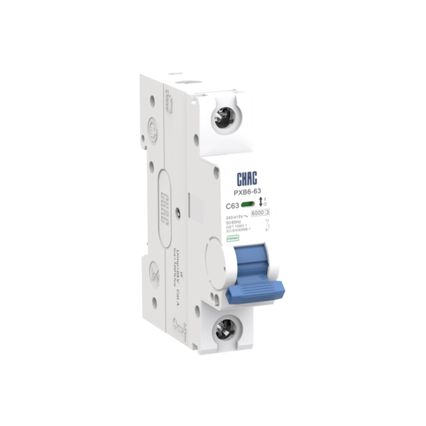
PXB6-63
قاطع دارة مصغر
تحقق من التيار المقنن، وعدد الأقطاب، ومنحنى الإغلاق.
عرض المنتج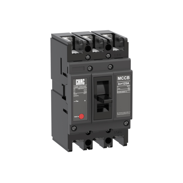
CQM6
قاطع الدائرة في الصندوق المطلي
راجع الهيكل، ووحدة التحرير، وقدرة القطع.
عرض المنتج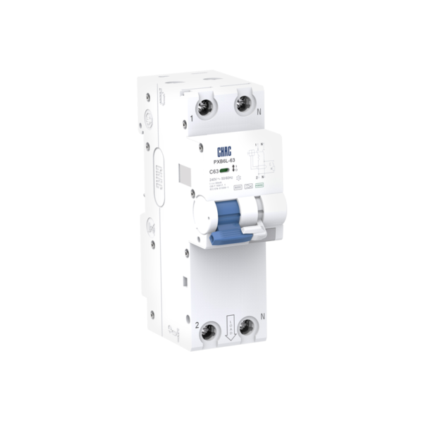
PXB6L-63
قاطع دارة تيار متبقي مع حماية من التيار الزائد
تحقق من نوع التيار المتبقي، وحساسية الجهاز، وقيم الحماية من التيار الزائد.
عرض المنتج