لنفترض مثلاً توسيعًا لمصنع يطلب فيه المشتري قاطعًا كهربائيًا مزوّدًا بحماية من الأعطال الأرضية، فيتلقى عرضين مختلفين تمامًا. يصف أحدهما حماية العاملين، بينما يشير الآخر إلى وظيفة قابلة للضبط لحماية المعدات. وكلاهما يذكر الأعطال الأرضية، لكن قبول أيٍّ منهما دون التحقق من الغاية المقصودة قد يؤدي إلى عدم استيفاء مواصفات المشروع. هذه مسألة توضيحية في مجال الشراء، وليست حالة تم الإبلاغ عنها في أحد المواقع.
ملخص: حماية المعدات من الأعطال الأرضية, يحدّ نظام الحماية من التيار الأرضي المتبقي (GFPE) من الأضرار الناجمة عن بعض أنواع الأعطال الأرضية، لكنه لا يحل محل نظام الحماية الشخصية بالدائرة الكهربائية المفقودة إلى الأرض (GFCI). ابدأ بتحديد ترتيب التأريض، والجهد بالنسبة للأرض، وتصنيف جهاز الفصل، وإصدار الكود المعتمد؛ ثم حدد نظام الاستشعار حتى الإغلاق بالكامل واختبارات القبول الخاصة به.
كيف يختلف حماية المعدات GFPE عن حماية الأفراد GFCI
يؤدي العطل الأرضي إلى إنشاء مسار تيار غير مقصود بين موصل مكهرب والأرض أو الأجزاء الموصلة المؤرضة. ويعتمد مقدار التيار الناتج على مصدر الطاقة، وترتيب التأريض، ومقاومة مسار العطل. وتنتج بعض الأعطال تيارات عالية جدًا، بينما قد تتسبب أعطال أخرى في تسخين ضار أو حدوث قوس كهربائي دون أن يصل التيار إلى عتبة الفصل الفوري لقاطع الحماية التقليدي.
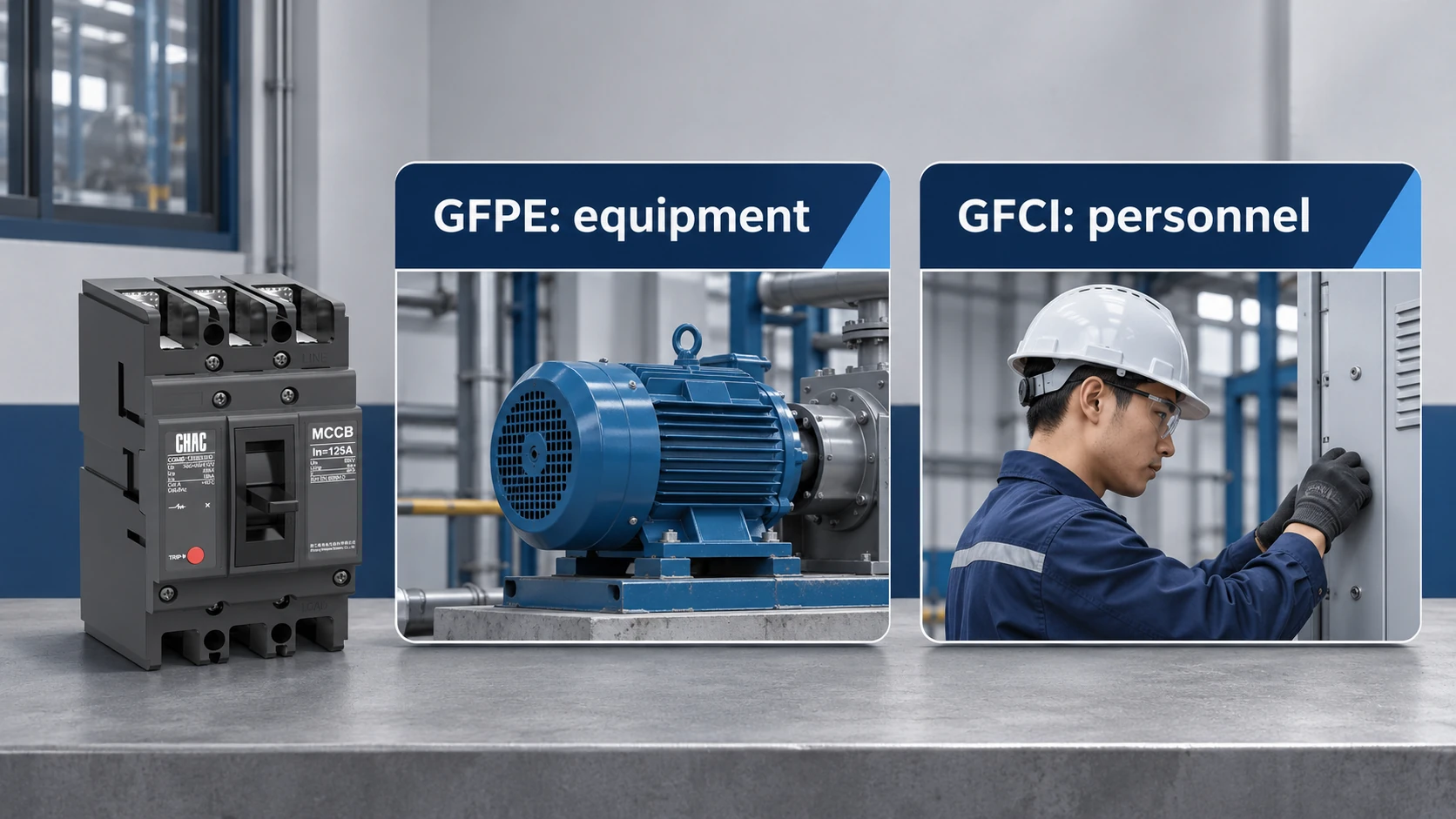
يكتشف جهاز GFPE حالة خطأ أرضي مناسبة ويبدأ في فصل التيار لحماية المعدات. أما جهاز GFCI فله غرض مختلف: تقليل خطر الصدمة الكهربائية ضمن ظروف التشغيل المحددة له. يُوصف تشغيل جهاز GFCI من الفئة A عادةً بنطاق تيار يتراوح بين 4 و6 مللي أمبير، في حين قد يستخدم نظام حماية المعدات إعدادات أعلى بكثير تُختار وفقًا لتطبيقه. إن مصطلح "خطأ أرضي" وحده لا يحدد مستوى الحماية.
| حماية | Main purpose | ما الذي يجب تأكيده |
|---|---|---|
| حماية التيار الزائد التقليدية | يستجيب للحمولات الزائدة والدوائر القصيرة وفقاً لخصائصه. | منحنى الترحيل، حماية الموصلات والقدرة على القطع |
| جي إف بي إي | الحد من أضرار المعدات الناجمة عن حالات الأعطال الأرضية المشمولة بالتأمين | ترتيب الاستشعار، جهاز الالتقاط، مسار التأخير ومسار الانطلاق |
| جهاز حماية من التسرب الأرضي من الفئة أ | توفير حماية من التيار الأرضي للموظفين وفقًا لمعاييرها القياسية. | Required listing, circuit application and operating characteristics |
| Ground-fault monitoring only | Report a detected condition | Whether it alarms only or also initiates disconnection |
A ground-fault alarm is therefore not automatically GFPE, and an equipment-protection relay is not automatically a personnel-protection device. Specify the required action as well as the detection function. For terminology and application context, the GFCI definition guide provides a useful companion explanation.
When do voltage, grounding and circuit location trigger GFPE requirements?
For a grounded wye system, voltage to ground is a decisive detail. A 120/208 V system normally has 120 V from phase to neutral, while a 277/480 V system normally has 277 V. Comparing only the line-to-line numbers misses the distinction used in certain NEC ground-fault protection provisions.
NEC 230.95 is the familiar service-equipment reference. In commonly adopted recent editions, its central application includes specified solidly grounded wye services above 150 V to ground, not exceeding 1,000 V phase to phase, with service disconnects rated 1,000 A or more. That description is a screening aid: the adopted edition, exceptions and actual arrangement must be checked by the designer and authority having jurisdiction.
Feeders and branch circuits require separate review, including NEC 215.10 and 210.13 where applicable. Do not assume that a service-level rule answers every downstream question. Nor does being below one threshold establish that ground-fault protection has no engineering value or that another applicable rule cannot require it.
Grounding details matter just as much as voltage. A solidly grounded wye system, an impedance-grounded system and an ungrounded system cannot be treated as interchangeable. The one-line diagram should identify the source grounding method, neutral path and relevant bonding points before a supplier proposes a sensing arrangement.
How to verify the complete GFPE sensing and tripping system
Common approaches include residual measurement using phase and, where needed, neutral current transformers; zero-sequence sensing around the relevant current-carrying conductors; and ground-return sensing in suitable arrangements. The correct choice depends on the system topology and equipment design. A diagram should show which conductors pass through each sensor and where the intended bonding paths are located.
In a residual or zero-sequence scheme, an incorrectly routed neutral or an unintended parallel return path can affect the measured imbalance. Sensor polarity, ratios and wiring also matter. These are installation-specific checks, not reasons to copy a generic wiring sketch onto a different switchboard.
Follow the complete operating chain: detection, relay or trip-unit decision, trip command, breaker opening and recorded indication. A relay test that proves only its output contact does not by itself prove that the installed breaker opens correctly. The acceptance plan should distinguish component tests from a functional test of the assembled protection path.
| المرحلة | Required information | أدلة القبول |
|---|---|---|
| System definition | Grounding, voltages, sources and neutral arrangement | Approved one-line and grounding drawings |
| Detection | Sensor type, ratio, polarity and conductor routing | Installation checks against the approved design |
| القرار | Pickup and delay with adjustment limits | Recorded settings and coordination review |
| Disconnection | Trip interface and breaker compatibility | Functional operating test appropriate to the system |
| Handover | Test method, results and final drawings | Dated records identifying the actual equipment |

Select GFPE pickup and delay from the protection coordination study
Pickup and time delay must be selected together. A very sensitive upstream setting can interrupt a larger part of the facility than intended. An excessive threshold or delay can permit more fault damage. Neither setting should be chosen merely because another plant uses it.
The engineer needs fault-study results, downstream protective-device characteristics, normal leakage information where relevant and equipment withstand limits. Coordination may also involve manufacturer-supported functions such as zone-selective interlocking. Such a function must be explicitly specified and supported by the devices involved; it cannot be assumed from a ground-fault label.
Commercial comparisons should include the sensor, trip accessory, control supply where required, settings work, commissioning and documentation. A lower device price can become a higher installed cost if a necessary sensor or compatible trip interface was excluded. Request a complete scope before comparing quotations.
What to include when specifying a breaker for GFPE
IEC 60947-2 covers circuit-breaker requirements within its scope. A reference to that standard does not, on its own, establish compliance with a particular NEC installation requirement or confirm that every breaker variant includes GFPE. Likewise, a product photograph cannot establish its trip functions.
تشاكس CQM6 standard MCCB range can be a starting point for a breaker discussion, but this article does not identify that standard model as a complete GFPE solution. Ask for the exact trip-unit designation, supported sensing arrangement and application documents before including any proposed model in a GFPE specification.
A useful request contains four items: the one-line diagram, destination-market requirements, protection study or required settings, and the acceptance-test scope. Ask the supplier to mark exclusions explicitly. That gives the panel builder and commissioning team a consistent basis for reviewing the offer.
Common questions about ground-fault protection of equipment
What is ground-fault protection of equipment?
It is protection intended to limit equipment damage from qualifying ground faults by detecting the condition and causing disconnection. Its sensitivity and operating time depend on the system and device. It is not a substitute for personnel GFCI protection.
What is the difference between GFPE and GFCI protection?
GFPE primarily protects equipment, while GFCI protection addresses electric-shock risk within its specified operating conditions. Their thresholds and application standards differ. One should not be substituted for the other because both detect ground faults.
When is ground-fault protection of equipment required by the NEC?
Applicability depends on the adopted edition, grounding arrangement, voltage, equipment rating and circuit location. Review service, feeder and branch-circuit provisions separately, including relevant exceptions. NEC 230.95 is a common starting point for service equipment, not a universal answer for every circuit.
Why can a standard overcurrent breaker miss a damaging ground fault?
A high-impedance or arcing fault may produce current below an instantaneous pickup or may persist within an overcurrent time-delay region. That can allow equipment damage before ordinary overcurrent protection operates. The actual response depends on the fault and trip characteristic.
Why do GFPE requirements differ between 120/208 V and 277/480 V systems?
Their usual phase-to-ground voltages are 120 V and 277 V respectively. Certain NEC provisions use voltage to ground as an applicability condition, so these systems can fall on different sides of a threshold. Other conditions and local adoption still apply.
How are GFPE pickup current and time delay selected?
They are established through a protection and coordination review using the actual system, downstream devices and equipment limits. Record the approved settings and adjustment ranges. Avoid treating factory defaults as a completed engineering study.
What performance testing is required after installing a GFPE system?
Follow the adopted code, manufacturer instructions and approved commissioning procedure. Where NEC 230.95 applies, check its initial performance-testing and written-record requirements in the adopted edition. The test scope should establish that the installed sensing and tripping arrangement operates as intended.
المراجع
- NFPA 70: edition and standard information
- 29 CFR 1926.404: electrical protection requirements for covered construction work
- IEC 60947-2: circuit-breaker standard scope
Protection is only as clear as its specified purpose and verified trip path. Send CHAC your breaker and protection requirements with the one-line diagram so the proposed product scope can be checked.