When a panel builder in Manchester encountered repeated trips after commissioning a three-phase conveyor, he moved the overload setting upward and the starter failed again within the next production cycle. In this illustrative scenario, the reversal came when the team compared the motor nameplate current with the measured starting time: the relay was not defective; its trip class and operating conditions had been selected without the actual start profile.
ملخص: Size a thermal overload relay from the motor nameplate current—not horsepower alone—then verify that its adjustable range includes that current. Select the trip class against the measured or manufacturer-published acceleration time, check ambient-compensation limits and reset mode, and confirm the complete starter combination with the contactor and upstream short-circuit protective device (SCPD). IEC 60947-4-1:2023, corrected version 2026-03, covers relevant low-voltage contactors, starters and motor protective switching devices up to 1,000 V AC or 1,500 V DC; it does not make one percentage setting or one trip class correct for every motor.
How Motor Nameplate Data Determines Relay Size
The first input for overload relay sizing is the rated motor current shown on the nameplate for the actual voltage and connection. A 3 hp rating does not uniquely determine current: voltage, phase, frequency, efficiency, power factor, motor design and connection all matter. A catalog full-load-current table can support preliminary panel design, but it should not silently replace the installed motor’s data.
Use a selection sequence that can be audited:
- Record the nameplate rated current for the intended supply and winding connection.
- Select a relay whose published adjustment band contains that current; do not choose a range merely because the motor horsepower appears in a distributor table.
- Set and commission the device only according to its instructions, the motor data, the starting profile and the destination rules. There is no universal percentage setting that is safe to publish for every installation.
- Compare cold and hot starting behavior with the manufacturer’s time-current curve, including the number of starts per hour and the shortest restart interval.
- Record the final setting, trip class, reset mode and tested starter combination on the panel schedule.
The hidden cost of getting this sequence wrong is rarely the relay price. An overly sensitive selection can stop a sound process during acceleration; an overly permissive selection can leave the motor exposed to sustained heating. Both outcomes create troubleshooting time, return claims and avoidable production interruption.
How Motor Starting Time Determines Trip Class
Trip class describes the relay’s time-to-trip behavior under defined test conditions; it is not the same as an ampere setting and is not a statement of breaking capacity. ABB’s technical note explains common IEC trip classes through time-current behavior, while the exact curve and tolerances remain device-specific. The engineering question is whether the motor can complete a normal start with margin while the relay still limits damaging stalled or prolonged-current conditions.
| Starting evidence | Trip-class direction to investigate | Decision check before approval |
|---|---|---|
| Fast, repeatable acceleration with a light inertial load | A faster class, commonly in the Class 10 family, may fit | Plot the measured start time against the exact relay curve; check hot restart and start frequency |
| Longer acceleration caused by higher inertia | A slower class, such as Class 20, may be considered | Confirm that the motor’s permitted thermal duty supports the longer acceleration; do not solve a mechanical or voltage problem by simply slowing protection |
| Very long, engineered acceleration | Class 30 or a configurable electronic function may be evaluated | Require motor thermal data, start-current data and a manufacturer-approved coordination path |
| Frequent starts, plugging, jogging, reversing or uncertain acceleration | No class should be selected from a generic table alone | Review the duty cycle, hot-state curve, contactor utilization and motor supplier limits |
This table is a decision frame, not a universal prescription. The class number by itself does not reveal the complete trip curve, cold-versus-hot response or phase-failure behavior. Compare the actual device data with the motor’s permitted locked-rotor or acceleration time. If that evidence is unavailable, hold approval rather than compensating with a higher setting.
Why Trip Class and Current Setting Are Not the Same
The current setting establishes the relay’s reference point for sustained load. Trip class describes how quickly the overload function acts at the standard test multiple defined for that class. Changing one to compensate for the other can create a protection gap: a current setting should not be raised to let a normal long start pass when the correct task is to evaluate starting duty and trip class.
How Ambient Temperature, Phase Loss, and Reset Mode Affect Selection
Thermal response depends on more than motor current. A bimetal relay located beside heat-producing devices in a closed enclosure may experience a different ambient temperature from the motor. Siemens’ ambient-compensation guidance is a useful reminder that compensation has a published operating range and construction-specific limits; it is not permission to ignore enclosure temperature, spacing or derating instructions.
| Selection dimension | What to verify | Why it changes the decision |
|---|---|---|
| Ambient conditions | Minimum and maximum panel temperature, enclosure ventilation, adjacent heat sources and manufacturer compensation range | Motor and relay may be at different temperatures; nuisance trips or delayed response can result if the published limits are exceeded |
| Three-phase sensing | All required poles are routed as instructed and the selected relay’s phase-failure or unbalance response is documented | A basic overload element is not automatically a full phase-monitoring relay; sensitivity and operating logic vary |
| Reset mode | Manual or automatic reset, local access, remote indication and restart interlocks | Automatic reset can create an unexpected-restart hazard unless the control system prevents automatic re-energization |
| Mounting and conductor path | Direct mounting or separate mounting, conductor size, terminal torque and orientation | Heat transfer, mechanical fit and connection reliability depend on the manufacturer’s installation conditions |
| Starting method | Direct-on-line, reversing, star-delta, soft starter or drive-fed motor | The relay location and sensed current can differ; a conventional line-side selection rule may not transfer unchanged |
Phase loss deserves a clear boundary. Some three-pole thermal overloads incorporate differential or phase-failure sensitivity, but that feature and its response must be confirmed in the datasheet. Voltage unbalance, current unbalance, phase sequence and open-phase detection may require separate monitoring depending on the process and destination rules. Likewise, overload protection does not diagnose bearing damage, blocked ventilation or every high-temperature condition unless the chosen protection system has suitable sensors.
How to Coordinate the Relay with the Contactor and Short-Circuit Device
A contactor makes and breaks the motor circuit during normal control operations. The overload relay detects sustained overcurrent and normally opens an auxiliary contact in the coil circuit. The upstream fuse or circuit breaker interrupts short-circuit current. These are three distinct jobs in motor starter protection; the overload relay is not the branch short-circuit protective device.
| Component | Primary function | Evidence needed for the combination |
|---|---|---|
| Contactor | Switch the motor according to the applicable utilization category and duty | Rated operational current, motor duty, coil voltage, operating frequency and auxiliary-contact requirements |
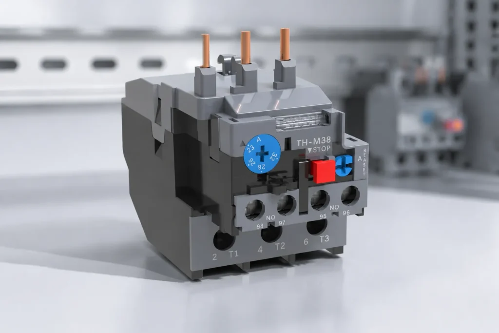
| Overload relay | Respond to sustained overload according to its setting and trip curve | Adjustment range, trip class, ambient limits, phase-loss behavior, reset mode and mounting compatibility |
| Fuse or circuit breaker | Interrupt short-circuit current within its ratings | Available fault current, device rating and a manufacturer-published coordination table for the exact combination |
IEC 60947-4-1 uses coordination concepts for starters and their SCPDs. Type 1 and Type 2 coordination describe the condition of the starter after a specified short-circuit test; they are outcomes for a tested combination, not labels that can be inferred from component ampere ratings. A panel builder should obtain the manufacturer’s coordination evidence for the exact contactor, overload relay and SCPD at the relevant prospective short-circuit current. Do not claim a coordination type by mixing independently suitable components.
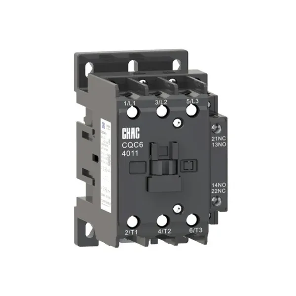
The same discipline applies to mechanical and electrical fit. Confirm that the relay is approved for direct mounting to the selected AC contactor platform, that its terminals and bus geometry match, and that the normally closed trip contact is correctly incorporated into the control circuit. The related contactor-versus-control-relay guide explains why a control relay cannot replace the power-switching contactor.
What the Current Standard and RFQ Should Cover
IEC 60947-4-1:2023, corrected version 2026-03, is the principal current IEC reference in this decision frame. Its scope includes electromechanical contactors and starters and motor protective switching devices for circuits up to 1,000 V AC or 1,500 V DC. It addresses equipment characteristics, testing and starter/SCPD coordination; it is a product standard and test framework, not proof that an unspecified device or assembled panel is certified.
Applicability still depends on the destination market, system voltage, installation rules, intended use and claims placed on the panel. A standard number printed in an RFQ is not enough: buyers should request the relevant declaration, report or coordination table and verify that the model, ratings and combination match the supplied equipment. Unsupported certification or coordination claims can cause approval delays, rejected submittals and liability exposure.
Motor Data and RFQ Checklist
| حقل طلب عرض الأسعار | Information to provide | Document to request |
|---|---|---|
| Motor identity | Photo or transcription of rated voltage, rated current, frequency, phase, connection, power, duty and service factor when shown | Motor datasheet and permitted start/locked-rotor information |
| Starting profile | Starting method, measured or predicted acceleration time, starts per hour, hot-restart interval and load inertia | Time-current curves for the proposed relay and trip class |
| Installation | Panel ambient range, enclosure arrangement, altitude where relevant, mounting method and conductor details | Installation, ambient-compensation and derating instructions |
| Control behavior | Manual or automatic reset, remote indication, PLC inputs and restart policy | Auxiliary-contact diagram and reset instructions |
| Starter combination | Contactor model and rating, supply voltage, utilization duty, SCPD model/rating and available fault current | Coordination table or test evidence for the exact combination and required destination |
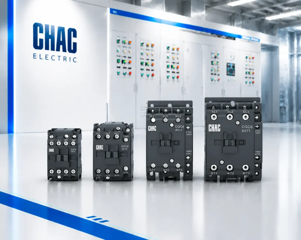
For a three-phase starter RFQ, CHAC Electric can review the documented selection inputs against the مرحل الحمل الزائد الحراري سلسلة CQR2 and a compatible contactor route. This is a product-family starting point, not a substitute for motor data, project engineering or destination-market verification.
Questions Panel Builders Ask About Overload Relays
How do I calculate the size of a thermal overload relay?
Start with the motor nameplate rated current for the actual voltage and connection, then choose a relay adjustment range that includes that current. Apply the exact device instructions and destination rules, and validate the setting against the motor’s start profile, ambient conditions and duty; do not apply one universal percentage.
What is trip class on an overload relay?
Trip class identifies time-to-trip performance under defined test conditions, helping engineers compare the relay response with motor acceleration and stall withstand. It does not state short-circuit breaking capacity, and the full manufacturer curve—including cold and hot behavior—must be checked.
How to size a motor overload relay?
Record nameplate current, select a compatible adjustment band, then verify trip class, starting frequency, ambient limits, phase-loss behavior and reset mode. Finally, confirm the exact relay/contactor/SCPD combination with published coordination evidence.
What is the overload protection size for a 3 hp motor?
Horsepower alone is insufficient to give a safe setting because a 3 hp motor’s rated current varies with voltage, phase, design, efficiency and connection. Use the nameplate current and governing installation rules; treat generic motor-current tables only as preliminary design aids until the actual motor data is available.
Can an overload relay replace a circuit breaker or fuse?
No. A conventional overload relay is intended for sustained overload response and relies on an appropriately selected upstream SCPD to interrupt short-circuit current. The complete starter combination must be coordinated for the available fault current.
Should the overload relay use manual or automatic reset?
Choose reset mode from the machine risk assessment and operating procedure. Manual reset supports investigation before restart; automatic reset requires control logic that prevents unexpected re-energization and must be permitted by the equipment instructions and destination rules.
Sources for Thermal Overload Relay Selection
- IEC 60947-4-1:2023, Low-voltage switchgear and controlgear—Contactors and motor-starters
- ABB, Trip Class technical note
- Siemens, Ambient compensation for overload relays
- CHINT, Guide to understanding trip curves for overload relays
The durable rule is simple: protect the motor you actually have, through the start it actually makes, with a starter combination supported by evidence.
Send the nameplate, starting profile, panel ambient range, reset requirement, contactor details and upstream SCPD information through CHAC Electric’s contact page to request a documented selection review.