


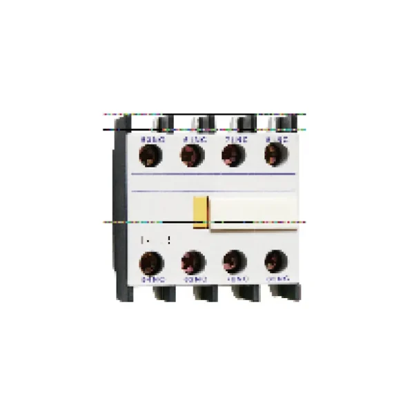


Hochleistungsschaltkontakten und Zubehörteile der Serie CQC1
Der Hochleistungsschaltkontakten und Zubehörteile der Serie CQC1 Das ist ein CHAC-AC-Kontaktor für Fernschaltung und Motorsteuerung. Die Seite enthält die modellspezifische technische Tabelle und Originalbilder des Produkts, damit Käufer die Spannung, den Strom, die Konfiguration, die Montage und die anwendbaren Normen vor der Bestellung überprüfen können. Die endgültige Eignung hängt von dem kompletten Schaltkreis, der Installationsmethode und den Bestimmungen des Bestimmungsmarktes ab.
Produktübersicht
CQC1 Series High-Duty AC Contactor and Accessories is a AC contactor intended for remote switching and motor control. The current product record identifies it for motor starters, HVAC and automation panels. Use the exact model variant and preserved technical source as the basis for procurement rather than assuming that every family member has the same rating.
Überprüfte Quellenübersicht: Model and Meaning Note 1: 09A~95A is in the form of auxiliary contact, and 115A~800Aisconventional without auxiliary10 indicates three normally open main contacts and one normally open auxiliary contact (32A and below)01 represents three normally open main contacts and one normally closed auxiliary contact (32A and below)11 represents three normally open main contacts, one normally open and one normally closed auxili
Hauptmerkmale
Typische Anwendungen
Typical use can include motor starters, HVAC and automation panels when the project confirms system voltage, current, fault or surge exposure, conductor and enclosure requirements, and the selected variant’s installation instructions. This page does not replace the project design or the authority having jurisdiction.
Antragsformular und Auswahlhinweis
Verwenden Sie die folgenden Entscheidungsstellen mit den gespeicherten Modelldaten. Die Produktfamilienbeschreibungen geben die Absicht an, aber die genaue technische Tabelle bestimmt die geordnete Variante.
| Auswahlpunkt | Hochleistungsschaltkontakten und Zubehörteile der Serie CQC1 | Was das Projekt bestätigen muss |
|---|---|---|
| Anwendung | AC Contactor projects | Bestätigen Sie die tatsächliche System- und Umgebungsanforderung |
| Auswahlgrundlage | Fernschaltung und Motorsteuerung | Verwenden Sie das genaue Modell und die technische Tabelle |
| Installation | Folgen Sie den Anweisungen im Modell | Kontrolle der Montage, der Abstands- und Abschlussmaßnahmen |
| Compliance | Verwenden Sie die angegebene Standardeinstellung, falls erforderlich. | Überprüfung der Ausgabe-, Umfangs- und Zielregelungen |
| Produkte in der Nähe | Bewerten Sie die zugehörige CHAC-Familie, bei der die Funktion unterschiedlich ist | Sämtliche Ersatzteile dürfen ohne technische Überprüfung nicht eingesetzt werden. |
Funktion
Fernschaltung und Motorsteuerung
Passt die Schutz- oder Schaltfunktion an das System an.
Konfiguration
Modellspezifische Optionen
Bestätigen Sie die aktuellen Werte für Stromstärke, Spannung, Polzahl, Anschlüsse oder Zubehörteile aus der Tabelle.
Installation
Mechanische und elektrische Anpassung
Überprüfen Sie die Gehäusekonstruktion, die Montage, die Kabeldurchführung und den Zugang zur Wartung.
Projektnachweise
Dokumente und Testprotokolle
Behalten Sie das genehmigte Bauzeichnung, das technische Datenblatt und die Inbetriebnahmeprotokolle bei.
Anleitung zum Bestellen
- Geben Sie das genaue Modell und die Variante an.
- Geben Sie die Systemspannung, den Strom, die Frequenz und die Last bzw. die Schutzfunktion an.
- Überprüfen Sie die Montage, die Anschlüsse, die Zubehörteile, das Gehäuse und die Umweltbedingungen.
- Teilen Sie die Menge, den Zielmarkt und die erforderlichen technischen Dokumente mit.
Installations- und Koordinationskontrollen
- Vergleichen Sie die Bewertungen des Modells und die Verbindungsanordnung mit den Projektzeichnungen.
- Überprüfen Sie die Anforderungen an Leiter, Busleitung, Gehäuse, Freiräume und Festigkeitsanforderungen anhand der Produktdokumentation.
- Koordinieren Sie gegebenenfalls Schutz- oder Kontrollvorrichtungen sowohl in der Nähe als auch in der Ferne.
- Verwenden Sie qualifizierte Mitarbeiter für Installation, Prüfung, Isolierung und Instandhaltung.
Model and Meaning

Note 1: 09A~95A is in the form of auxiliary contact, and 115A~800Aisconventional without auxiliary10 indicates three normally open main contacts and one normally open auxiliary contact (32A and below)01 represents three normally open main contacts and one normally closed auxiliary contact (32A and below)11 represents three normally open main contacts, one normally open and one normally closed auxiliary contact (40~95A).
Appearance and installation dimensions
CQC1-09 12、18、25、32
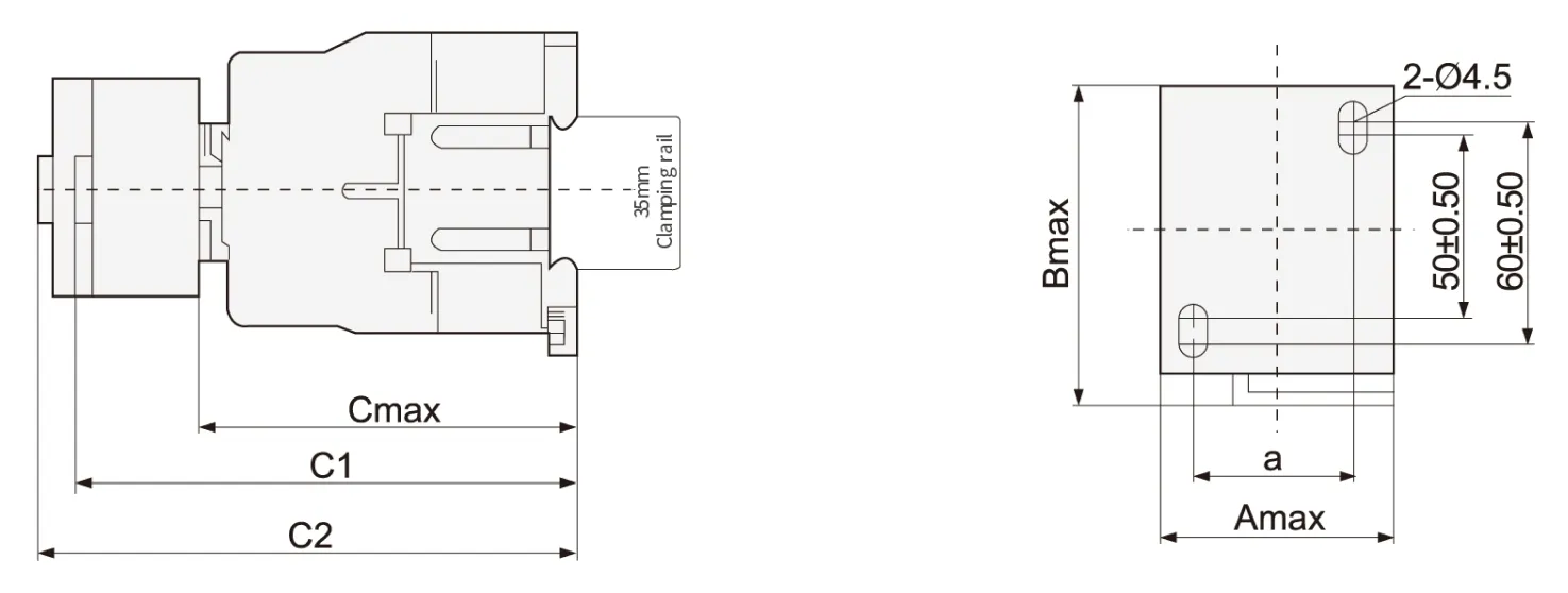
| Contactor model | Amax | Bmax | Cmax | a | C1 | C2 |
| CQC1-09、12 | 47 | 76 | 82 | 35±0.50 | 113 | 133 |
| CQC1-18 | 87 | 118 | 138 | |||
| CQC1-25 | 57 | 86 | 95 | 40±0.50 | 126 | 146 |
| CQC1-32 | 100 | 131 | 151 |
Note: C1:CQC1+F4 C2:CQC1+S4
CQC1-40、50、65、80、95
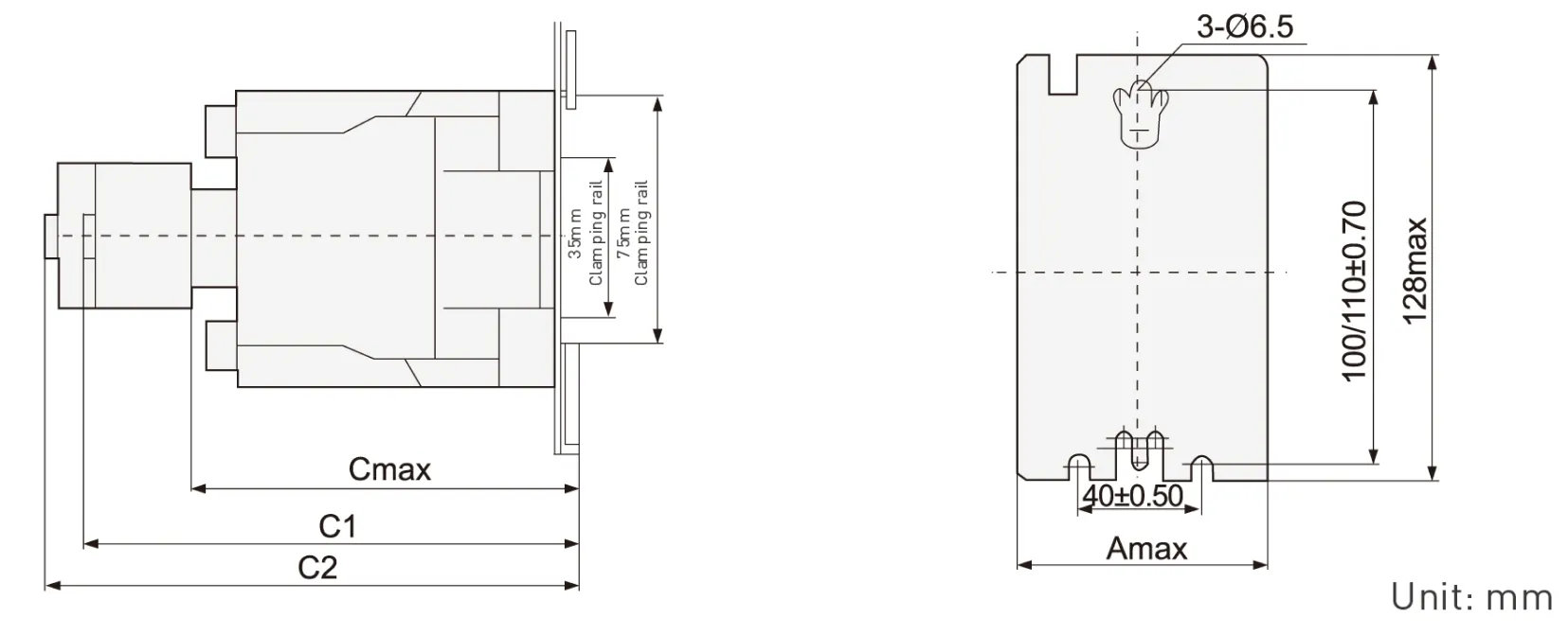
| Contactor model | Amax | Cmax | C1 | C2 |
| CQC1-4011-6511 | 77 | 116 | 145 | 165 |
| CQC1-8011~9511 | 87 | 127 | 175 | 195 |
Note:C1:CQC1+F4 C2:CQC1+S4
C0C1-115~330 overall dimensions and installation dimensions [tolerance: ± 1mm]

| CQC1 | a | P | Q | Q1 | S | Φ | f | b | b1 | M | N | c | L | G | H | Φ1 | G1 | Z | Y | X1 | |
| ≤500V | >500V | ||||||||||||||||||||
| 115 | 163.5 | 37 | 29.5 | 60 | 20 | M6 | 131 | 162 | 137 | 147 | 124 | 171 | 107 | 80 | 120-106 | 6.5 | 106 | 13.5 | 44 | 10 | 15 |
| 150 | 163.5 | 40 | 26 | 57.5 | 20 | M8 | 131 | 170 | 137 | 150 | 124 | 171 | 107 | 80 | 120-106 | 6.5 | 106 | 13.5 | 44 | 10 | 15 |
| 185 | 168.5 | 40 | 29 | 59.5 | 20 | M8 | 130 | 174 | 137 | 154 | 127 | 181 | 113.5 | 80 | 120-106 | 6.5 | 111 | 13.5 | 44 | 10 | 15 |
| 225 | 168.5 | 48 | 21 | 51.5 | 25 | M10 | 130 | 197 | 137 | 172 | 127 | 181 | 113.5 | 80 | 120-106 | 6.5 | 111 | 13.5 | 44 | 10 | 15 |
| 265 | 205 | 48 | 39 | 66.5 | 25 | M10 | 147 | 203 | 145 | 180 | 147 | 213 | 141 | 96 | 120-106 | 6.5 | 140 | 20.5 | 38 | 10 | 15 |
| 330 | 213 | 48 | 43 | 74 | 25 | M10 | 147 | 209 | 145 | 184 | 158 | 219 | 145 | 96 | 120-106 | 6.5 | 154.5 | 20.5 | 38 | 10 | 15 |
Note: f is the space required for coil replacement
X1 is the minimum electrical clearance [Flying Fox distance)the same as below
CQC1-400-500 overall dimensions and installation dimensions(tolerance: ± 1mm)
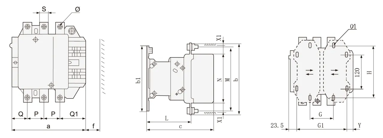
| CQC1 | a | P | Q | Q1 | S | Φ | f | b | b1 | M | N | c | L | G | G1 | Φ1 | H | Y | X1 | |
| ≤500V | >500V | |||||||||||||||||||
| 400 | 213 | 48 | 43 | 74 | 25 | M10 | 151 | 206 | 209 | 181 | 158 | 219 | 145 | 80(66-102) | 170(156-192) | 8.5 | 180 | 19.5 | 15 | 20 |
| 500 | 233 | 46 | 46 | 77 | 30 | M10 | 169 | 238 | 209 | 208 | 172 | 232 | 146 | 80(66-102) | 170(156-210) | 8.5 | 180 | 39.5 | 15 | 20 |
CQC1-630-800 overall dimensions and installation dimensions(tolerance: ± 1mm)
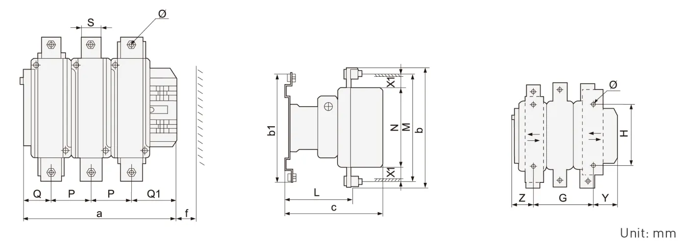
| CQC1 | a | P | Q | Q1 | S | Φ | f | b | b1 | M | N | c | L | G | H | Φ1 | Z | Y | X1 | |
| ≤500V | >500V | |||||||||||||||||||
| 630/800 | 309 | 80 | 60 | 89 | 40 | M12 | 201 | 304 | 280 | 264 | 202 | 255 | 155 | 180(100-195) | 180 | 10.5 | 60.5 | 68.5 | 20 | 30 |
CQC1 Series Accessories
Quick selection table/specification

Specification of auxiliary contact [air delay type]
| model | Delay range | Number of delayed contacts | Delay mode | Hook mode |
| S4-20 | 0.1s~3s | 1NO+1NC | Power on delay | Top hanging |
| S4-22 | 0.1s~30s | |||
| S4-24 | 10s~180s | |||
| S5-20 | 0.1s~3s | Power off delay | ||
| S5-22 | 0.1s~30s | |||
| S5-24 | 10s~180s |
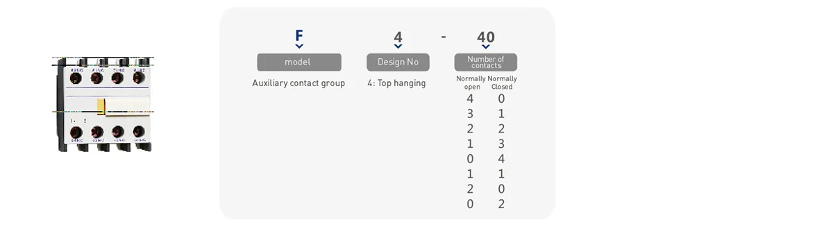
Auxiliary contact specification
| model | Number of contacts | Hook mode | |
| Normally open [NO] | Normally Closed [NC] | ||
| F4-40 | 4 | 0 | C0C1-09~95 series contactors are top mounted CQC1-115-800 series contactors are side mounted |
| F4-31 | 3 | 1 | |
| F4-22 | 2 | 2 | |
| F4-13 | 1 | 3 | |
| F4-04 | 0 | 4 | |
| F4-20 | 2 | 0 | |
| F4-11 | 1 | 1 | |
| F4-02 | 0 | 2 | |
Technical parameters
09~95A performance index
| CQC1-09 | COC1-12 | COC1-18 | COC1-25 | COC1-32 | COC1-40 | COC1-50 | COC1-65 | CQC1-80 | CQC1-95 | |||
| Rated working current le,A(AC-3) | 400V | 9 | 12 | 18 | 25 | 32 | 40 | 50 | 65 | 80 | 95 | |
| 690V | 6.6 | 8.9 | 12 | 18 | 21 | 34 | 39 | 42 | 49 | 49 | ||
| Agreed free air heating current lth (A) | 25 | 25 | 25 | 40 | 40 | 65 | 80 | 80 | 125 | 125 | ||
| Rated working voltage Ue (V) | 380/400、660/690 | |||||||||||
| Rated insulation voltage Ui (V) | 690V | |||||||||||
| AC-3(6le、le) | Electrical life (times) | 200×104 | 200×104 | 200×104 | 200×104 | 200×104 | 200×104 | 200×104 | 200×104 | 200×104 | 200×104 | |
| Frequent operation(h) | 1200 | 1200 | 1200 | 1200 | 600 | 600 | 600 | 600 | 600 | 600 | ||
| AC-4(6le、6le ) | Electrical life (times) | 20×10 | ||||||||||
| Frequent operation(h) | 300 | |||||||||||
| Rated working current le(A) | 380/400V | 3.5 | 5 | 7.7 | 8.5 | 12 | 18.5 | 24 | 28 | 37 | 44 | |
| 660/690V | 1.5 | 2 | 3.8 | 4.4 | 7.5 | 9 | 12 | 14 | 17.3 | 21.3 | ||
| Mechanical life (times) | 1000×104 | 800×104 | 600×104 | |||||||||
| Auxiliary contact | Agreed free air heating current lth(A) | 10 | ||||||||||
| Electrical life (times) | AC-15(360VA) | 100×104 | 80×104 | 60×1043 | ||||||||
| DC-13(33W) | ||||||||||||
| Minimum load that can be connected | 24V 10mA | |||||||||||
| Spule | Rated control supply voltage Us (V) | AC(50Hz/60Hz)24、36、110、220、380;DC:24、48、110、220 | ||||||||||
| pull-in voltage | 85%~110%Us | |||||||||||
| Release voltage | 20%~75% US(AC)10%~75% Us(DC) | |||||||||||
| 50Hz AC coil power (VA) | start | 65 | 65 | 65 | 100 | 100 | 200 | 200 | 200 | 200 | 200 | |
| Sorption | 8 | 8 | 8 | 11 | 11 | 20 | 20 | 20 | 20 | 20 | ||
| DC coil power (w) | start | 11 | 11 | 11 | 13 | 13 | 22 | 22 | 22 | 22 | 22 | |
| Sorption | ||||||||||||
| Wiring capacity of termina mm²(min/max) | Non prefabricated end cord | 1 piece | 1/4 | 1.5/6 | 1.5/10 | 2.5/10 | 2.5/25 | 4/50 | ||||
| 2 pieces | 1/4 | 1.5/6 | 1.5/6 | 2.5/10 | 2.5/16 | 4/25 | ||||||
| Flexible wire with prefabricated end | 1 piece | 1/4 | 1/6 | 1/6 | 1/9 | 2.5/25 | 4/50 | |||||
| 2 pieces | 1/2.5 | 1/4 | 1/4 | 1.5/6 | 2.5/10 | 4/16 | ||||||
| Non prefabricated end hard wire | 1 piece | 1/4 | 1.5/6 | 1.5/6 | 1.5/10 | 2.5/25 | 4/50 | |||||
| 2 pieces | 1/4 | 1.5/6 | 1.5/6 | 1.5/10 | 2.5/16 | 4/25 | ||||||
| Tightening torque of main circuit wiring | N·M | 1.7 | 2.5 | 5 | 9 | |||||||
115A-800A performance index
| technical parameter | CQC1-115 | CQC1-150 | CQC1-185 | CQC1-225 | CQC1-265 | CQC1-330 | CQC1-400 | CQC1-500 | CQC1-630 | CQC1-800 | ||
| Rated working current le(A) | AC-3 | 400V | 115 | 150 | 185 | 225 | 265 | 330 | 400 | 500 | 630 | 800 |
| 690V | 86 | 107 | 118 | 135 | 172 | 225 | 305 | 355 | 460 | 485 | ||
| AC-4 | 400V | 52 | 60 | 79 | 85 | 105 | 117 | 138 | 147 | 188 | 242 | |
| 690V | 49 | 57 | 69 | 82 | 98 | 107 | 135 | 145 | 170 | 215 | ||
| Maximum rated power of controllable three-phase squirrel cage motor Pe (k) | AC-3 | 400V | 55 | 75 | 90 | 110 | 132 | 160 | 200 | 250 | 335 | 450 |
| 690V | 80 | 100 | 110 | 129 | 160 | 220 | 280 | 335 | 450 | 475 | ||
| AC-4 | 400V | 25 | 30 | 40 | 45 | 55 | 63 | 75 | 80 | 100 | 129 | |
| 690V | 45 | 51 | 63 | 75 | 90 | 100 | 129 | 140 | 160 | 200 | ||
| Agreed free air heating current lth (A) | 200 | 200 | 280 | 280 | 360 | 360 | 580 | 580 | 850 | 850 | ||
| Rated working voltage Ue (V) | 400、690 | |||||||||||
| Rated insulation voltage Ui (V) | 690 | |||||||||||
| AC-3 | Electrical life (times) | 60×104 | 50×104 | 30×104 | 20×104 | 15×104 | ||||||
| Frequent operation (h) | 600 | 300 | 150 | |||||||||
| AC-4 | Electrical life (times) | 15×104 | 8×10⁴ | 5×10⁴ | 3×10⁴ | |||||||
| Frequent operation (h) | 150 | |||||||||||
| Mechanical life (times) | 300×104 | 100×104 | 60×104 | |||||||||
| Auxiliary contact | Agreed free air heating current lth (A) | 10 | ||||||||||
| Electrical life (times) | AC-15(360VA) | 60×104 | 50×104 | 30×104 | 15×104 | |||||||
| DC-13(33W) | ||||||||||||
| Coil parameters | Rated control supply voltage Us (V) | AC50HZ:24、48 110 230(220)240 (double coil energy-saving type(380) | AC50HZ:48、110 230(220)240 (double coil energy-saving type(380) | |||||||||
| pull-in voltage | 85%~110%Us | |||||||||||
| Release voltage | 20%~75%Us | |||||||||||
| coil power (VA) | start | 560 | 800 | 750 | 1000 | 1100 | 1600 | |||||
| Sorption | 45 | 55 | 8 | 12 | 16 | 20 | ||||||
| Pickup time (ms) | 23~35 | 20~35 | 30~65 | 40~75 | 40~80 | 50~100 | ||||||
| Release time (ms) | 5~15 | 7~15 | 100~170 | 100~170 | 100~200 | 130~230 | ||||||
| Main circuit connection capacity | Copper conductor | Number of roots | 1 | 1 | 1 | 1 | 1 | 1 | 2 | 2 | – | |
| Conductor section mm | 120 | 150 | 185 | 240 | 240 | 150 | 240 | – | ||||
| Copper bar | Number of roots | 2 | 2 | 2 | 2 | 2 | 2 | 2 | 2 | 2 | 2 | |
| Dimension mm | 20×3 | 25×3 | 25×3 | 32×4 | 32×4 | 30×5 | 30×5 | 50×5 | 60×5 | 60×5 | ||
| Auxiliary circuit contrd circuit | Flexible cord mm² |
1 | 2.5 | |||||||||
| 2 | ||||||||||||
| Hard wire mm² | 1 | 4 | ||||||||||
| 2 | ||||||||||||
Warum CHAC wählen?
Mit mehr als 30 Jahren Erfahrung in der Fertigung, 1100 Mitarbeitern und 100 Millionen Polen
Mit einer jährlichen Kapazität von 90% automatisierten Produktionslinien bietet CHAC eine stabile Produktionskapazität und strenge Qualitätskontrollen.
Qualitätskontrolle für globale OEM-/ODM-Kunden. Unser internes Fertigungssystem ermöglicht eine langfristige Zusammenarbeit.
Kooperation für Elektrohersteller, Importeure und Händler.

30+
JAHRE ERFAHRUNG
Specialisiert auf die Herstellung von Niederspannungselektronik

1100+
ARBEITER
Das professionelle Team gewährleistet eine stabile Qualität und Lieferfähigkeit.

100 Millionen+
JAHRESTERNE VON POLES
Großserienfertigung zur Deckung der weltweiten Nachfrage

90%
AUTOMATISCHE PRODUZIERUNG
Erweiterte Automatisierung für hohe Effizienz und Konsistenz
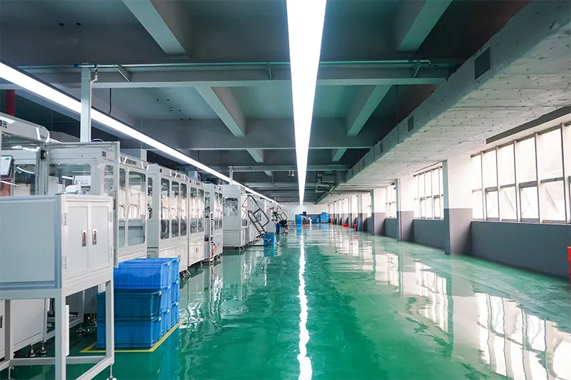
Automatisierte Montagelinie

Testlabor
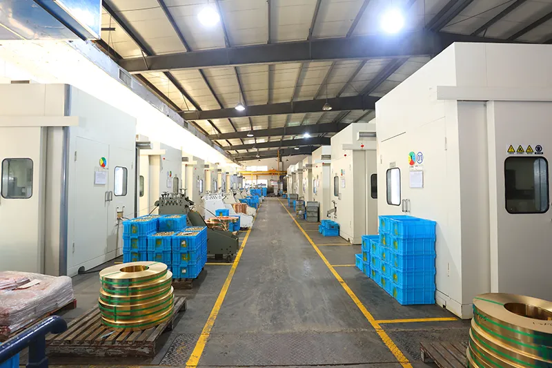
Injektion und Stempeln
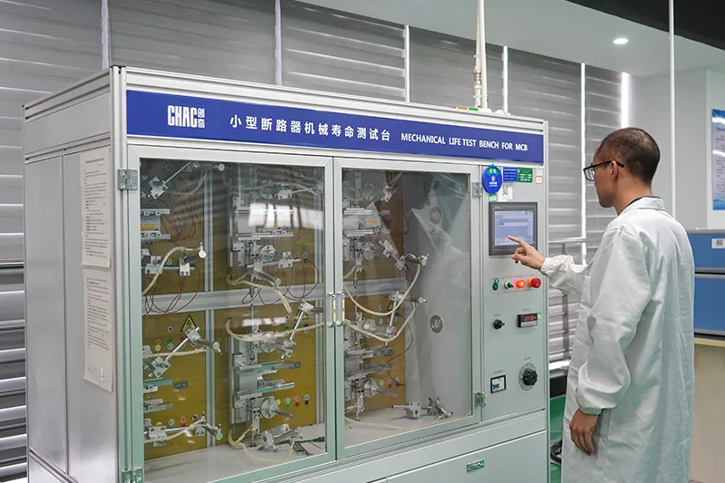
Qualitätskontrolle



Ein strenges Qualitätskontrollsystem gewährleistet, dass jedes Produkt den globalen Standards entspricht.
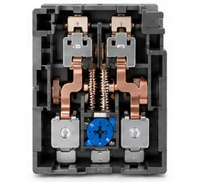
Was können wir anpassen?
CHAC supports customization of coil voltage, auxiliary contact configuration,
electrical parameters, product branding,packaging design and engineering development according to customers’ equipment and market requirements.

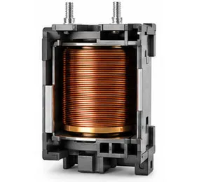
Spannung der Spule
Optionen für die Spannung der AC- und DC-Spulen, abgestimmt auf die Anforderungen der Anwendung.

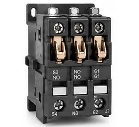
Hilfskontakte
Flexibler Zusatzkontaktaufbau für verschiedene Steuerfunktionen.

Elektrotechnische Parameter
Die aktuellen Bewertungen, Schutzbereiche und Funktionsparameter können individuell angepasst werden.

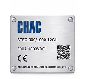
Produktbranding
Unterstützung für private Etikettenlogos, Namensschilder und Produktidentifizierung.

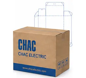
Verpackungsdesign
Kundenspezifische Kartons, Etiketten, Handbücher und Verpackungslösungen.

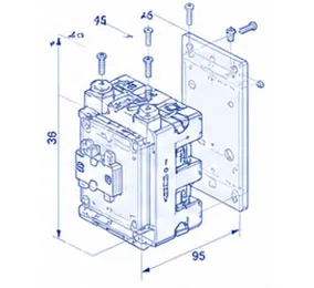
Technisches Entwicklungsprogramm
Support von der Zeichnungserstellung über die Produktentwicklung bis hin zur passenden Anwendung.
CQC1 Product FAQ
What loads can the CQC1 contactor switch?
Use the published utilization category, operational current and voltage for the selected variant. Resistive, motor and capacitive loads require different checks.
How do I select an AC contactor size?
Start with load current, utilization category, starts per hour, coil voltage, poles and short-circuit coordination. Current alone is not enough.
Can a thermal relay be paired with it?
Where the product record supports the combination, a thermal relay can form a motor starter. Confirm mechanical fit, current range and control wiring.
Which coil voltage should I specify?
Match the control supply shown on the project drawing with the coil option for the exact model. Never assume the coil voltage from the main circuit.
What accessories are available?
Auxiliary contacts, timers, interlocks or other accessories depend on the series and variant. Confirm the compatible accessory list before ordering.
How should a contactor be commissioned?
Verify terminal torque, coil voltage, contact sequence, insulation and operating current, then record the test results.
Confirm the Right CQC1 Configuration
Senden Sie das genaue Modell, die Betriebsanforderungen, die Menge, den Zielmarkt und die erforderlichen Dokumente. CHAC prüft die Anfrage anhand der veröffentlichten Produktdaten.
Ähnliche Produkte
-
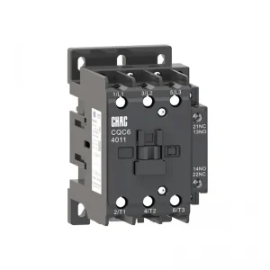
CQC6-Serie Industrielle AC-Schütze - OEM-Hersteller
-
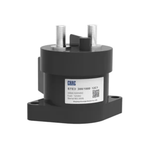
STE3-Serie Hochspannungs-DC-Kontaktor (rundes Keramikversiegelung)
-
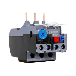
Thermostatischer Überlastrelais der CQR2-Serie
-
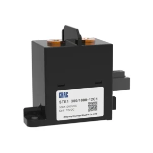
STE1-Serie Hochspannungs-DC-Kontaktor (Quadratischer Keramikverschluss)STE1-Serie Hochspannungs-DC-Kontaktor (Quadratischer Keramikverschluss)