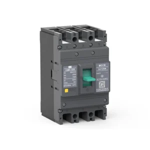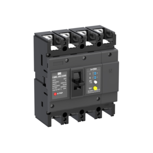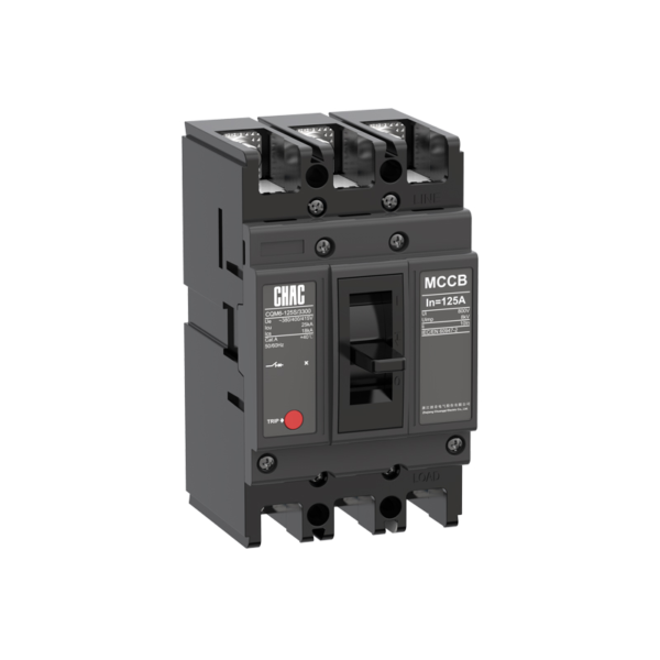
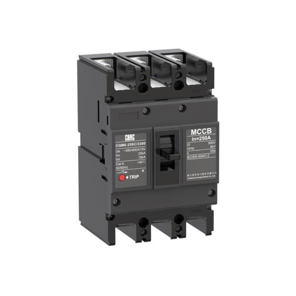
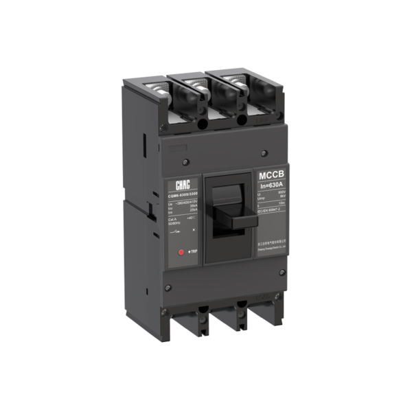
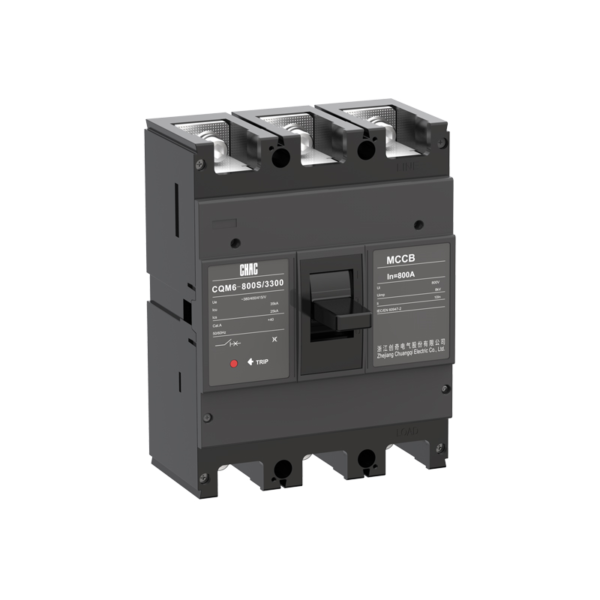
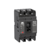
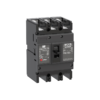
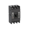
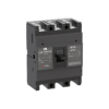
CQM6 Standardgehäuse-Schutzschalter (MCCB) – Hersteller für OEM-Produkte
Der CQM6 MCCB bietet Überlast- und Kurzschlussschutz innerhalb seines veröffentlichten 16–1600A-Bereichs. Die Spezifikation sollte sich an der Systemspannung, der Last, der Leiterkoordination, dem voraussichtlichen Fehlerstrom und den geltenden Vorschriften orientieren – nicht allein am Amperezahlwert.
Produktübersicht
CQM6 is a mccb breaker for AC distribution and protection applications. Its published range covers 16–1600A with 2P / 3P / 4P, depending on frame; CQM6-1600: 3P options. Selection depends on the complete power-system design, including fault level, coordination, conductor ampacity, enclosure conditions and local rules.
Die bereitgestellte Produktspezifikation verweist auf IEC/EN 60947-1, IEC/EN 60947-2, IEC/EN 60947-3 und IEC/EN 60947-4 sowie auf GB/T 14048.1, .2, .3 und .4. Diese Normreferenzen begründen an sich keine Zertifizierung für eine bestimmte Bestellung.
Hauptmerkmale
Typische Anwendungen
Typical applications include commercial, industrial and infrastructure distribution or motor circuits. These are evaluation contexts rather than universal approvals. Confirm the exact frame, voltage, breaking duty, trip unit, accessories and installation method before specification.
Antragsformular und Auswahlhinweis
Use the verified CQM6 values below to create a shortlist, then validate the complete circuit. An MCCB rating does not replace conductor calculations, fault-current analysis, coordination review or local installation requirements.
| Auswahlpunkt | CQM6 reference | Was das Projekt bestätigen muss |
|---|---|---|
| Bemessener Strom | 16–1600A | Bemessungsstrom, Leiterbelastbarkeit, Verlegeart, Temperatur und Gruppierung |
| Spannung | AC 400/415V; CQM6-1600 führt auch 660/690V-Konfigurationen auf | Auslegung des Versorgungssystems und der Anlagenausstattung |
| Masten | 2P / 3P / 4P, je nach Rahmen; CQM6-1600: 3P | Behandlung von stromführenden Leitern und dem Neutralleiter |
| Reise / Schutz | thermal-magnetic trip | Lastprofil, Fehlerreaktion und Koordination |
| Ausschaltvermögen | Klassen C/S/M/H/L, mit Icu bis zu 100kA für die aufgeführten CQM6-1600- und 660/690V-Konfigurationen; überprüfen Sie den genauen Rahmen und die Spannung. | Voraussichtlicher Kurzschlussstrom am Installationspunkt |
Feste vs. einstellbare Absicherung
Ein fest eingestelltes thermisch-magnetisches Schutzelement kann sich für ein stabiles Design eignen, während eine einstellbare Auslöseeinheit bei der Koordination hilfreich sein kann, wenn die Projektplanung Einstellungen vor Ort vorsieht.
Reisekoordination
MCCB-Optionen vergleichen →
MCCB vs. MCB
Ein Leistungsschalter für Niederspannung (MCCB) wird in der Regel hinsichtlich höherer Ströme, des Kurzschlussstromvermögens oder der Flexibilität bei der Auswahl von Zubehör bewertet; ein Miniatur-Leistungsschalter (MCB) kann für kompakte Endstromkreise besser geeignet sein.
Strom- und Fehlerbelastung
Vergleichen Sie MCCB und MCB →
ICU vs. ICS
The saved data for CQM6 lists C/S/M/H/L classes, with Icu up to 100kA for the listed CQM6-1600 660/690V configurations; verify the exact frame and voltage. Match the declared duty to the prospective short-circuit current and continuity objective.
Kurzschlussberechnung
Technischen Support überprüfen →
Anordnung von Phase und Neutralleiter
Published pole options are 2P / 3P / 4P, depending on frame; CQM6-1600: 3P. Confirm which conductors must be switched, protected and isolated together.
Systemanordnung
MCCB-Sortiment anzeigen →
Anleitung zum Bestellen
- State the exact model: CQM6.
- Provide frame and rated current within the published range: 16–1600A.
- Confirm poles: 2P / 3P / 4P, depending on frame; CQM6-1600: 3P.
- Specify the trip unit or protection function: thermal-magnetic trip.
- Bitte geben Sie die Systemspannung, die Frequenz, den Anwendungsbereich, das erwartete Kurzschlussstromniveau, den Zielmarkt und die Menge an.
- Führen Sie die erforderlichen Zubehörteile, Anschlüsse, Dokumente sowie alle zugelassenen OEM-/ODM-Kennzeichnungs- oder Verpackungsanforderungen auf.
Installations- und Koordinationskontrollen
- Verwenden Sie ausschließlich die spezifische Modellzeichnung und die dazugehörigen Anweisungen; leiten Sie keine Schlussfolgerungen hinsichtlich der Klemmenpositionen, der Versorgungsrichtung oder der Zubehörkompatibilität aus einem anderen Leistungsschalter ab.
- Überprüfen Sie das Leitermaterial und den Querschnitt anhand der Schaltungsdimensionierung, der Klemmendaten, der Temperatur sowie der Gruppierung.
- Bestätigen Sie die Kurzschluss- bzw. Fehlerstrombelastbarkeit der Schaltgeräte, die Koordination zwischen vorgeschalteten und nachgeschalteten Komponenten, die Gehäusebedingungen, die Höhe über dem Meeresspiegel sowie die Freiräume.
- Installation, Isolierung, Prüfung und Wartung dürfen nur von qualifiziertem Personal gemäß den geltenden Vorschriften durchgeführt werden.
Auswahlhilfe

| Product code ① | Extension Code ② | Shell frame grade ③ | Breaking capacity ④ | Operating method ⑤ | Number of poles ⑥ | |||||
|---|---|---|---|---|---|---|---|---|---|---|
| CQM6 | G | 125 | C | P | 4 | |||||
| Molded case circuit breaker | —:Thermal and magnetic protection are not adjustable G:Overload alarm without trip function |
C | S | L | M | H | P:Motorized operation Z:Turning handle W.Direct operation |
125A:2P,3P,4P 160A:3P,4P 250A:2P,3P,4P 400A:3P,4P 630A:3P,4P 800A:3P,4P 1250A:3P,4P 1600A:3P |
||
| 125 | 125 | 15/8 | 25/18 | / | / | / | ||||
| 160 | 160 | 25/18 | 35/25 | / | 50/35 | / | ||||
| 250 | 250 | 25/18 | 35/25 | / | 50/35 | / | ||||
| 400 | 400 | / | 35/25 | / | 50/35 | 70/50 | ||||
| 630 | 630 | / | 35/25 | / | 50/35 | 70/50 | ||||
| 800 | 800 | / | 35/25 | / | 50/35 | 70/50 | ||||
| 1250 | 1250 | / | / | / | 50/35 | 70/55 | ||||
| 1600 | 1600 | / | / | 70/20 | 100/35 | 100/50 | ||||
| Trip Unit &Accessories ⑦ | Rated current A ⑧ | Function ⑨ | 4P Option Code ⑩ | Special code ⑪ | |
|---|---|---|---|---|---|
| 300 | 125A | 2 | A | I | |
| The first digit indicates the type of detent 2:instantaneous detent only 3:Duplicate detent Note:The last two digits are the accessory designator(see accessory table). |
125 | 16,20,32,40,50,63,80,100,125 | 1:For power distribution 2:For motor protection |
A:N-pole is unprotected and cannot be combined B:N-pole is unprotected and can be combined C:N-pole is protected and can be combined D:N-pole is protected and cannot be combined |
I:Overload alarm non trip function |
| 160 | 16,20,32,40,50,63,80,100,125,140,160 | ||||
| 250 | 100,125,140,160,180,200,225,250 | ||||
| 400 | 250,315,350,400 | ||||
| 630 | 250,315,350,400,500,630 | ||||
| 800 | 500,630,700,800 | ||||
| 1250 | 800,1000,1250 | ||||
| 1600 | 800,1000,1250,1400,1500,1600 | ||||
| Accessory Voltage ⑫ | Motorized operating voltage ⑬ | Installation ⑭ | Terminal Block Option ⑮ | |||
|---|---|---|---|---|---|---|
| Q1 | D1 | Q | 2 | |||
| Undervoltage detent Q1:AC220V Q2:AC240V Q3:AC380V Q4:AC415V | Shunt release F1:AC220V F2:AC380V F3:DC110V F4:DC24V | Auxiliary alarm J1:AC125V J2:AC250V J3:DC125V J4:DC24V | CD1 Electrical Operation D1:AC220V D2:AC230V D3:AC380V D4:AC400V |
CD2 Electrical Operation D5:AC230V D6:AC110V D7:DC220 D8:DC110 D9:AC110–240V D10:DC100–220V | Q:Front of plate H:Rear of plate C:Inserted | 1:Noinstitution 2:Installation |
| Note:When motorized operation is selected,please refer to the external accessories for the two voltages applicable for motorized operation. | ||||||
Zubehörliste
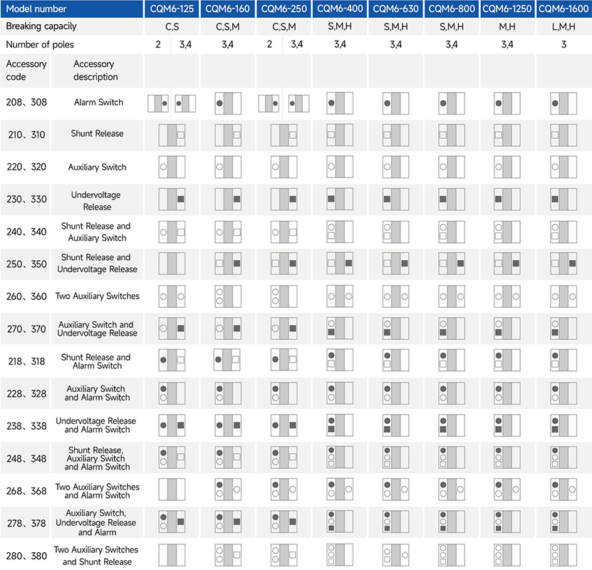
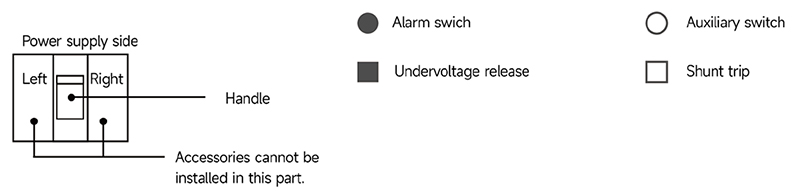
CHAC offers a right-side auxiliary switch, a left-side shunt release and a left-side undervoltage release.
For accessory codes 220, 320, 240, 340, 270 and 370, the auxiliary switch can provide two contact pairs. Specify this requirement when ordering.
For accessory codes 250 and 350, the shunt release and undervoltage release on frames 400 and above are available only for 3-pole circuit breakers.
Main Technical Parameters
| Modellnummer | CQM6-125 | CQM6-160 | |||||
|---|---|---|---|---|---|---|---|
| Rated current of frame level Inm(A) | 125 | 160 | |||||
| Anzahl der Pole | 2,3,4 | 3,4 | |||||
| Rated current In(A),at 40°C,50°C,55°C | 16,20,25,32,40,50,63,80,100,125 | 16,20,25,32,40,50,63,80,100,125,140,160 | |||||
| Rated operating voltage Ue(V),AC 50/60Hz | 400/415 | 400/415 | |||||
| Rated insulation voltage Ui (V) | 800 | 800 | |||||
| Rated impulse withstand voltage Uimp(KV) | 8 | 8 | |||||
| Breaking capacity designation | C | S | C | S | M | ||
| Short-circuit breaking capacity Icu/Ics(kA) | AC400/415V | 15/8 | 25/18 | 25/18 | 35/25 | 50/35 | |
| Selectivity category | A | A | A | A | A | ||
| Number of operating cycles(cycle) | ON | 6000 | 6000 | ||||
| OFF | 10000 | 10000 | |||||
| Trip mechanisms and protection types | Magnetic trip | Power distribution protection | ● | ● | ● | ● | ● |
| Motor protection | ● | ● | ● | ● | ● | ||
| Thermal-magnetic trip | Power distribution protection | ● | ● | ● | ● | ● | |
| Motor protection | ● | ● | ● | ● | ● | ||
| Zubehör | Auxiliary contacts | ● | ● | ● | ● | ● | |
| Alarm contacts | ● | ● | ● | ● | ● | ||
| Shunt disconnect | ● | ● | ● | ● | ● | ||
| Undervoltage detent | ● | ● | ● | ● | ● | ||
| Manual operating mechanism | ● | ● | ● | ● | ● | ||
| Motorized operating mechanism | ● | ● | ● | ● | ● | ||
| Backplane wiring | ● | ● | ● | ● | ● | ||
| Inserted | ● | ● | ● | ● | ● | ||
| Coupling plate | ● | ● | ● | ● | ● | ||
| Partition between phases | ● | ● | ● | ● | ● | ||
| Derivative products | Dedicated for prepayment electric meters | ● | ● | ● | ● | ● | |
| Overload alarm without trip | – | – | ● | ● | ● | ||
| Overall dimensions (mm) (a–b–c–ca) | 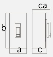 |
3 P | 75×130×68×91 | 90×155×70×95 | 90×155×85 ×109 | ||
| 4 P | 100×130×68×91 | 120×155×70×95 | 120×155×85 ×109 | ||||
Note: ● indicates an available optional accessory; – indicates that the accessory is not available.
Main Technical Parameters
| Modellnummer | CQM6-250 | CQM6-400 | CQM6-630 | ||||||||
|---|---|---|---|---|---|---|---|---|---|---|---|
| Rated current of frame level Inm(A) | 250 | 400 | 630 | ||||||||
| Anzahl der Pole | 2,3,4 | 3,4 | 3,4 | ||||||||
| Rated current In(A),at 40°C,50°C,55°C | 100,125,140,160,180,200,225,250 | 250,315,350,400 | 250,315,350,400,500,630 | ||||||||
| Rated operating voltage Ue(V),AC 50/60Hz | 400/415 | 400/415 | 400/415 | ||||||||
| Rated insulation voltage Ui (V) | 800 | 800 | 800 | ||||||||
| Rated impulse withstand voltage Uimp(KV) | 8 | 8 | 8 | ||||||||
| Breaking capacity designation | C | S | M | S | M | H | S | M | H | ||
| Short-circuit breaking capacity Icu/Ics(kA) | AC400/415V | 25/18 | 35/25 | 50/35 | 35/25 | 50/35 | 70/50 | 35/25 | 50/35 | 70/50 | |
| Selectivity category | A | A | A | A | A | A | A | A | A | ||
| Number of operating cycles (cycle) |
ON | 6000 | 3000 | 3000 | |||||||
| OFF | 10000 | 8000 | 8000 | ||||||||
| Trip mechanisms and protection types | Magnetic trip | Power distribution protection | ● | ● | ● | ● | ● | ● | ● | ● | ● |
| Motor protection | ● | ● | ● | ● | ● | ● | ● | ● | ● | ||
| Thermal-magnetic trip | Power distribution protection | ● | ● | ● | ● | ● | ● | ● | ● | ● | |
| Motor protection | ● | ● | ● | ● | ● | ● | ● | ● | ● | ||
| Zubehör | Auxiliary contacts | ● | ● | ● | ● | ● | ● | ● | ● | ● | |
| Alarm contacts | ● | ● | ● | ● | ● | ● | ● | ● | ● | ||
| Shunt disconnect | ● | ● | ● | ● | ● | ● | ● | ● | ● | ||
| Undervoltage detent | ● | ● | ● | ● | ● | ● | ● | ● | ● | ||
| Manual operating mechanism | ● | ● | ● | ● | ● | ● | ● | ● | ● | ||
| Motorized operating mechanism | ● | ● | ● | ● | ● | ● | ● | ● | ● | ||
| Backplane wiring | ● | ● | ● | ● | ● | ● | ● | ● | ● | ||
| Inserted | ● | ● | ● | ● | ● | ● | ● | ● | ● | ||
| Coupling plate | ● | ● | ● | ● | ● | ● | ● | ● | ● | ||
| Partition between phases | ● | ● | ● | ● | ● | ● | ● | ● | ● | ||
| Derivative products | Dedicated for prepayment electric meters | ● | ● | ● | ● | ● | ● | ● | ● | ● | |
| Overload alarm without trip | ● | ● | ● | ● | ● | ● | ● | ● | ● | ||
| Overall dimensions (mm) (a-b-c-ca) | |
3 P | 105×165×70×95 | 105×165×93×118 | 140×257×107×156 | 140×257×107×156 | |||||
| 4 P | 140×165×70×95 | 140×165×93×118 | 185×257×107×156 | 185×257×107×156 | |||||||
Note: ● indicates an available optional accessory; – indicates that the accessory is not available.
Main Technical Parameters
| Modellnummer | CQM6-800 | CQM6-1250 | CQM6-1600 | |||||||
|---|---|---|---|---|---|---|---|---|---|---|
| Rated current of frame level Inm(A) | 800 | 1250 | 1600 | |||||||
| Anzahl der Pole | 3,4 | 3,4 | 3 | |||||||
| Rated current In(A),at 40°C,50°C,55°C | 500,630,700,800 | 800,1000,1250 | 800,1000,1250,1400,1500,1600 | |||||||
| Rated operating voltage Ue(V),AC 50/60Hz | 400/415 | 400/415 | 400/415V | 660/690V | ||||||
| Rated insulation voltage Ui (V) | 800 | 1000 | 1000 | |||||||
| Rated impulse withstand voltage Uimp(KV) | 8 | 12 | 12 | |||||||
| Breaking capacity designation | S | M | H | M | H | L | M | H | ||
| Short-circuit breaking capacity Icu/Ics(kA) | AC400/415V | 35/25 | 50/35 | 70/50 | 50/35 | 70/55 | 70/20 | 100/35 | 100/50 | |
| Selectivity category | A | A | A | A | A | A | A | A | ||
| Number of operating cycles (cycle) |
ON | 1000 | 1000 | 500 | ||||||
| OFF | 3000 | 3000 | 3000 | |||||||
| Trip mechanisms and protection types | Magnetic trip | Power distribution protection | ● | ● | ● | ● | ● | ● | ● | ● |
| Motor protection | ● | ● | ● | ● | ● | ● | ● | ● | ||
| Thermal-magnetic trip | Power distribution protection | ● | ● | ● | ● | ● | ● | ● | ● | |
| Motor protection | ● | ● | ● | ● | ● | ● | ● | ● | ||
| Zubehör | Auxiliary contacts | ● | ● | ● | ● | ● | ● | ● | ● | |
| Alarm contacts | ● | ● | ● | ● | ● | ● | ● | ● | ||
| Shunt disconnect | ● | ● | ● | ● | ● | ● | ● | ● | ||
| Undervoltage detent | ● | ● | ● | ● | ● | ● | ● | ● | ||
| Manual operating mechanism | ● | ● | ● | ● | ● | ● | ● | ● | ||
| Motorized operating mechanism | ● | ● | ● | ● | ● | ● | ● | ● | ||
| Backplane wiring | ● | ● | ● | ● | ● | ● | ● | ● | ||
| Inserted | ● | ● | ● | ● | ● | ● | ● | ● | ||
| Coupling plate | ● | ● | ● | ● | ● | ● | ● | ● | ||
| Partition between phases | ● | ● | ● | ● | ● | ● | ● | ● | ||
| Derivative products | Dedicated for prepayment electric meters | ● | ● | ● | ● | ● | ● | ● | ● | |
| Overload alarm without trip | ● | ● | ● | ● | ● | ● | ● | ● | ||
| Overall dimensions (mm) (a–b–c–ca) | |
3 P | 210×275×113×162 | 210×275×113×162 | 210×268×161×240 | |||||
| 4 P | 280×275×113×162 | 280×275×113×162 | ||||||||
Note: ● indicates an available optional accessory; – indicates that the accessory is not available.
Operating Characteristics
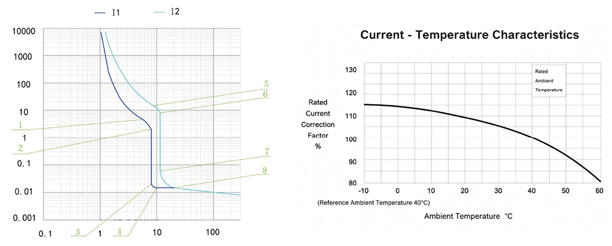
The following table gives the inverse-time operating characteristics for distribution protection with all poles energised at an ambient temperature of +40°C, without humidity compensation.
| Test current designation | Setting current multiple | Conventional time | Initial state |
|---|---|---|---|
| In≤63 63<In | |||
| Conventional non-tripping current | 1.05 | ≥1h ≥2h | Cool state |
| Conventional tripping current | 1.30 | <1h <2h | Hot state |
The following table gives the inverse-time operating characteristics for motor protection with all poles energised at an ambient temperature of +40°C, without humidity compensation.
| Test current designation | Setting current multiple | Conventional time | Initial state |
|---|---|---|---|
| In≤800 | |||
| Conventional non-tripping current | 1.0 | ≥2h | Cool state |
| Conventional tripping current | 1.2 | <2h | Hot state |
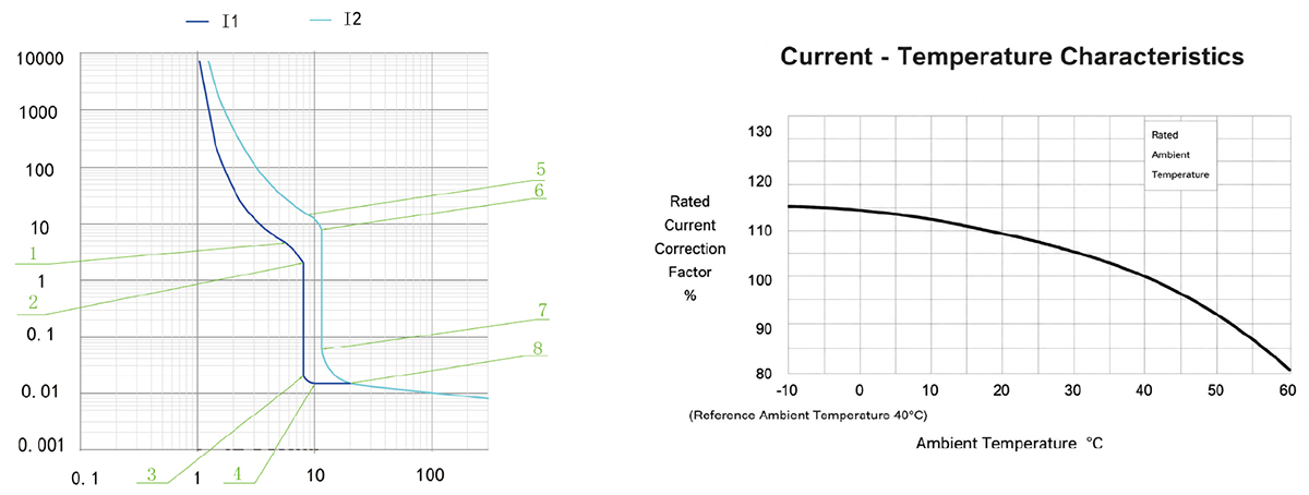
The operating-characteristics reference gives an instantaneous trip current setting of 10In for distribution protection. Confirm the applicable trip-unit setting for the ordered configuration.
The operating-characteristics reference gives an instantaneous trip current setting of 12In for motor protection.
The stated accuracy of the instantaneous trip current setting is 20% of the setting value.
CQM6-125 Betriebskennlinie
CQM6-160 Operating Characteristic Curve
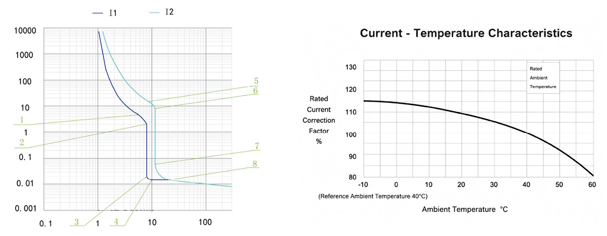
CQM6-250 Operating Characteristic Curve
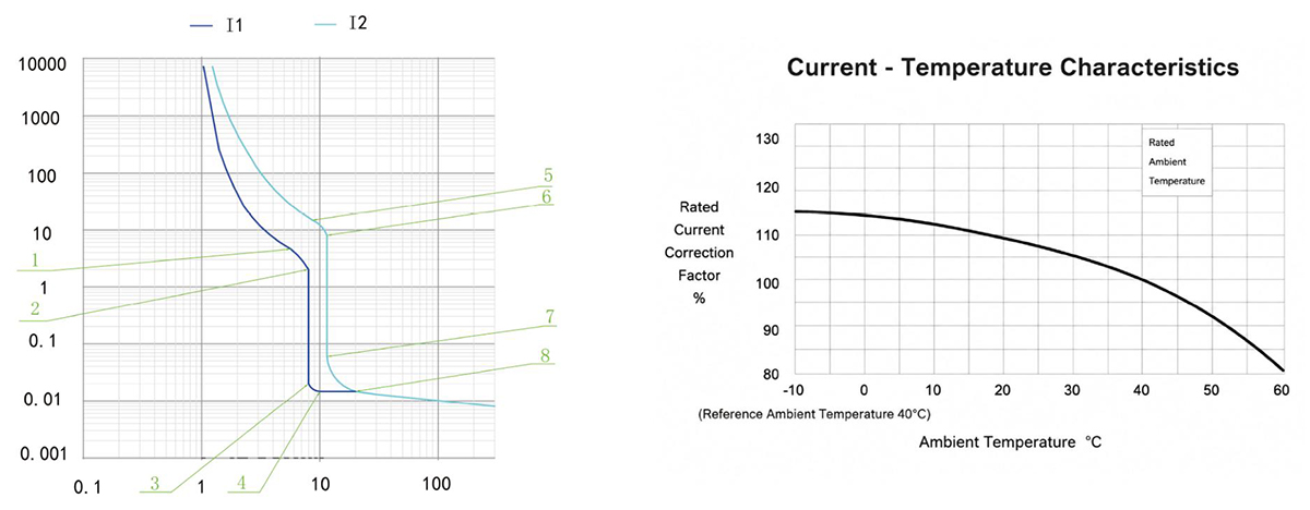
CQM6-400 / 630 Operating Characteristic Curve
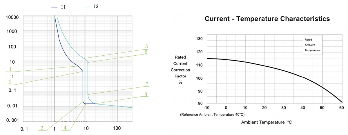
CQM6-800 Operating Characteristic Curve
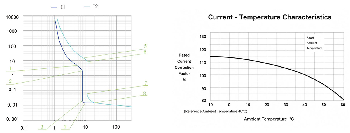
CQM6-1250 Operating Characteristic Curve
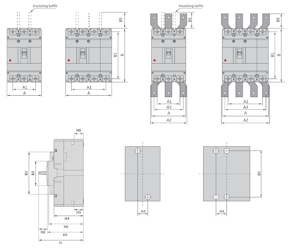
CQM6-125~1250 Outline and Installation Dimensions(mm)
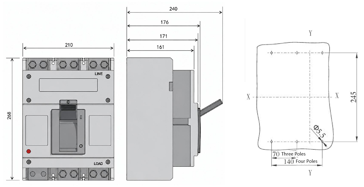
CQM6-1600 Outline and Installation Dimensions(mm)
| Molded case circuit breaker | Overall dimension | Installation dimensions | Boit | |||||||||||||||||||||
|---|---|---|---|---|---|---|---|---|---|---|---|---|---|---|---|---|---|---|---|---|---|---|---|---|
| A | A1 | A2 | A3 | B | B1 | B2 | B3 | B5 | B6 | H | H1 | H2 | H3 | H4 | H5 | H6 | A4 | B4 | ||||||
| 3P | 4P | 3P | 4P | 3P | 4P | 3P | 4P | |||||||||||||||||
| CQM6-125CSM | 75 | 100 | 50 | 75 | – | – | – | – | 130 | 114 | 85 | 50 | 48 | – | 91 | 73.4 | 2.4 | 68 | 61 | 23.9 | 24 | 25 | 111 | M6 |
| CQM6-160CS | 90 | 120 | 60 | 90 | – | – | – | – | 155 | 134 | 103 | 50 | 48 | – | 95 | 75.5 | 2.1 | 70 | 62 | 24 | 24.8 | 30 | 132 | M8 |
| CQM6-160M | 90 | 120 | 60 | 90 | – | – | – | – | 155 | 134 | 103 | 50 | 48 | – | 109.5 | 90 | 2.1 | 85 | 76.5 | 23.6 | 25 | 30 | 132 | M8 |
| CQM6-250CS | 105 | 140 | 70 | 105 | – | – | – | – | 165 | 144 | 102 | 50 | 97 | – | 95 | 74.2 | 2.7 | 70 | 61.4 | 22.3 | 23.1 | 35 | 126 | M8 |
| CQM6-250M | 105 | 140 | 70 | 105 | – | – | – | – | 165 | 144 | 102 | 50 | 95 | – | 118.5 | 97.7 | 2.7 | 93.4 | 84.8 | 22.9 | 23.3 | 35 | 126 | M8 |
| CQM6-400SMH | 140 | 185 | 70 | 132 | 140 | 196 | 112 | 168 | 257 | 230 | 179 | 90 | 103 | 42 | 156 | 111.7 | 3.5 | 107.5 | 99.5 | 30.9 | 32.4 | 44 | 194 | M10 |
| CQM6-630SMH 400A | 140 | 185 | 88 | 132 | 140 | 196 | 112 | 168 | 257 | 230 | 179 | 90 | 103 | 42 | 156 | 111.7 | 3.5 | 107.5 | 99.5 | 30.9 | 32.4 | 44 | 194 | M10 |
| CQM6-630SMH 630A | 140 | 185 | 88 | 132 | 140 | 196 | 112 | 168 | 257 | 230 | 179 | 90 | 103 | 42 | 156 | 111.7 | 3.5 | 107.5 | 99.5 | 33.2 | 34 | 44 | 194 | M10 |
| CQM6-800SMH 630A | 210 | 280 | 140 | 210 | 180 | 250 | 140 | 210 | 275 | 243 | 192 | 90 | 103 | 87 | 162.5 | 118 | 2.7 | 113.4 | 105.5 | 28.3 | 30.4 | 70 | 242.5 | M12 |
| CQM6-800SMH 800A | 210 | 280 | 140 | 210 | 180 | 250 | 140 | 210 | 275 | 243 | 192 | 90 | 103 | 87 | 162.5 | 118 | 2.7 | 113.4 | 105.5 | 29 | 32.6 | 70 | 242.5 | M12 |
| CQM6-1250SMH | 210 | 280 | 140 | 210 | 180 | 250 | 140 | 210 | 275 | 243 | 192 | 90 | 103 | 87 | 162.5 | 118 | 2.7 | 113.4 | 105.5 | 31.3 | 34.4 | 70 | 242.5 | M10 |
| CQM6-1600LMH | 210 | – | 140 | – | – | – | – | – | 268 | 240 | 118 | 97 | 110 | – | 240 | 171 | 5 | 161 | 150 | 33 | 34 | 70 | 245.0 | M10 |
Warum CHAC wählen?
Mit mehr als 30 Jahren Erfahrung in der Fertigung, 1100 Mitarbeitern und 100 Millionen Polen
Mit einer jährlichen Kapazität von 90% automatisierten Produktionslinien bietet CHAC eine stabile Produktionskapazität und strenge Qualitätskontrollen.
Qualitätskontrolle für globale OEM-/ODM-Kunden. Unser internes Fertigungssystem ermöglicht eine langfristige Zusammenarbeit.
Kooperation für Elektrohersteller, Importeure und Händler.

30+
JAHRE ERFAHRUNG
Specialisiert auf die Herstellung von Niederspannungselektronik

1100+
ARBEITER
Das professionelle Team gewährleistet eine stabile Qualität und Lieferfähigkeit.

100 Millionen+
JAHRESTERNE VON POLES
Großserienfertigung zur Deckung der weltweiten Nachfrage

90%
AUTOMATISCHE PRODUZIERUNG
Erweiterte Automatisierung für hohe Effizienz und Konsistenz
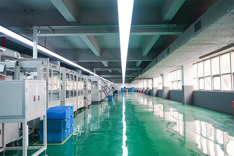
Automatisierte Montagelinie

Testlabor
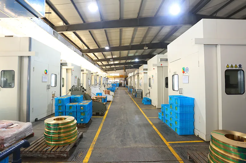
Injektion und Stempeln
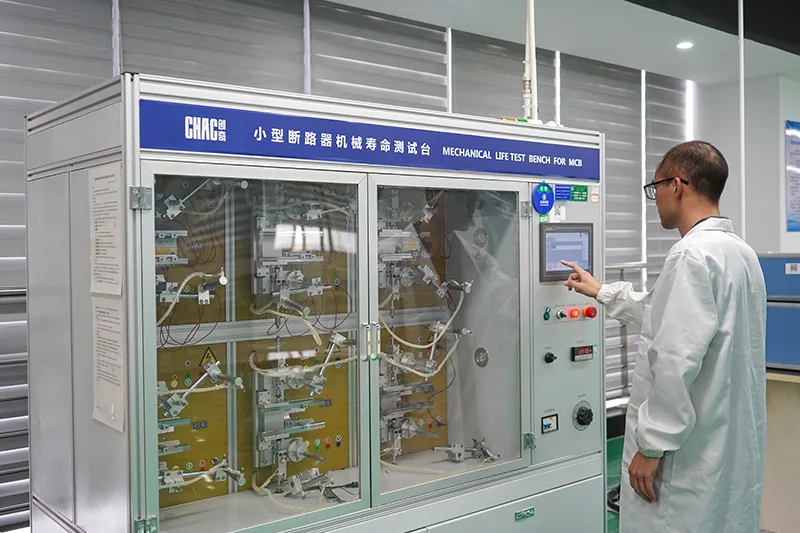
Qualitätskontrolle



Ein strenges Qualitätskontrollsystem gewährleistet, dass jedes Produkt den globalen Standards entspricht.
Was können wir anpassen?
For CQM6 projects, CHAC can review private-label marking, packaging, approved appearance options, published 16–1600A electrical configurations and technical-document requirements. Requests outside the published range are subject to engineering evaluation, testing, minimum order quantity and project feasibility.

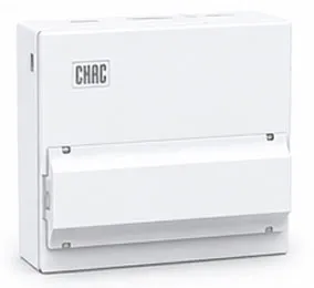
Gehäuse
Design
Passgenaue Gehäusegrößen, -strukturen und Installationsdetails.

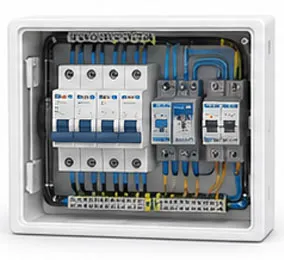
Interne
Konfiguration
Flexible Optionen für die interne Struktur und die Komponentenanordnung.

Markenbildung &
Logo
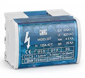
Private-Label-Logos, Namensschilder und Markeninformationen.

Verpackung
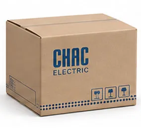
Design
Kundenspezifische Kartons, Etiketten, Handbücher und Verpackungslösungen.

Elektrisch
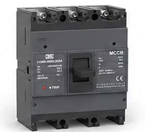
Konfiguration
Passgenaue elektrische Ausrüstung basierend auf den Anforderungen der Anwendung.

Zertifizierung
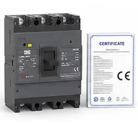
Support
Unterstützung für Standards und Compliance-Anforderungen des Zielmarktes.
Herunterladen
CQM6-Serie - Formschaltgetrennte Sicherung
Komplettes Produktüberblick für Niederspannungselektronikkomponenten und Referenz zur Produktauswahl.
Brauchen Sie technische Dokumente?
Kontaktieren Sie uns für Datenblätter, Zertifikate, Zeichnungen, Auswahlberatung oder Unterstützung bei OEM-/ODM-Projekten.
CQM6 Product FAQ
What is the CQM6 MCCB used for?
The CQM6 is specified for overload and short-circuit protection in AC systems at the voltage listed for the ordered frame within the published 16–1600A range. Suitability depends on the fault study, conductor coordination, enclosure and local rules.
How does the CQM6 molded case circuit breaker work?
The protection mechanism responds to the fault conditions stated for this model: overload and short-circuit protection. Trip behaviour, settings and interruption duty must be checked against the ordered frame and product instructions.
How do I choose the CQM6 rated current and poles?
Start with the design current and conductor calculation, then choose a published current within 16–1600A and poles from 2P / 3P / 4P, depending on frame; CQM6-1600: 3P. Neutral treatment, fault level, ambient conditions and coordination also need review.
What breaking capacity should I check on the CQM6?
Use the declared C/S/M/H/L classes, with Icu up to 100kA for the listed CQM6-1600 660/690V configurations; verify the exact frame and voltage for the exact frame, voltage and configuration. The prospective short-circuit current at the installation point must be within the applicable duty; a larger ampere value alone is not a selection rule.
Can the CQM6 replace an MCB or an earth-leakage device?
An MCCB is not automatically a like-for-like replacement. The CQM6 provides overload and short-circuit protection; residual-current protection, DC interruption, adjustable settings and other functions must be confirmed separately from the project requirement.
How should the CQM6 be installed and tested?
Use only the exact model drawing, terminal identification and accessory instructions. A qualified person should verify isolation, conductor size, torque, clearances, settings, fault duty and functional tests before energising the circuit.
Confirm the Right CQM6 Configuration
Send the frame, rated current, poles, protection function, system voltage, expected fault level, destination market and quantity. CHAC will review the request against the published model range.